

Peavey TransTube Series, TransTube Bandit 112, TransTube Studio Pro 112, TransTube Envoy 110 Operating Manual
Page 1

Bandit 112
®
Envoy 110
®
Envoy 110
®
Studio Pro 112
®
Studio Pro 112
®
Bandit 112
®
O p e r a t i n g G u i d e
All manuals and user guides at all-guides.com
all-guides.com
Page 2
Intended to alert the user to the presence of uninsulated “dangerous voltage” within the product’s
enclosure that may be of sufficient magnitude to constitute a risk of electric shock to persons.
Intended to alert the user of the presence of important operating and maintenance (servicing)
instructions in the literature accompanying the product.
CAUTION: Risk of electrical shock — DO NOT OPEN!
CAUTION: To reduce the risk of electric shock, do not remove cover. No user serviceable parts inside. Refer
servicing to qualified service personnel.
WARNING: To prevent electrical shock or fire hazard, do not expose this appliance to rain or moisture. Before
using this appliance, read the operating guide for further warnings.
Este símbolo tiene el propósito, de alertar al usuario de la presencia de “(voltaje) peligroso” sin ais-
lamiento dentro de la caja del producto y que puede tener una magnitud suficiente como para constituir
riesgo de descarga eléctrica.
Este símbolo tiene el propósito de alertar al usario de la presencia de instruccones importantes sobre la
operación y mantenimiento en la información que viene con el producto.
PRECAUCION: Riesgo de descarga eléctrica ¡NO ABRIR!
PRECAUCION: Para disminuír el riesgo de descarga eléctrica, no abra la cubierta. No hay piezas útiles dentro.
Deje todo mantenimiento en manos del personal técnico cualificado.
ADVERTENCIA: Para evitar descargas eléctricas o peligro de incendio, no deje expuesto a la lluvia o humedad
este aparato Antes de usar este aparato, Iea más advertencias en la guía de operación.
Ce symbole est utilisé dans ce manuel pour indiquer à l’utilisateur la présence d’une tension dangereuse
pouvant être d’amplitude suffisante pour constituer un risque de choc électrique.
Ce symbole est utilisé dans ce manuel pour indiquer à l’utilisateur qu’il ou qu’elle trouvera d’importantes
instructions concernant l’utilisation et l’entretien de l’appareil dans le paragraphe signalé.
ATTENTION: Risques de choc électrique — NE PAS OUVRIR!
ATTENTION: Afin de réduire le risque de choc électrique, ne pas enlever le couvercle. Il ne se trouve à l’intérieur
aucune pièce pouvant être reparée par l’utilisateur. Confiez I’entretien et la réparation de l’appareil à un réparateur
Peavey agréé.
AVERTISSEMENT: Afin de prévenir les risques de décharge électrique ou de feu, n’exposez pas cet appareil à la
pluie ou à l’humidité. Avant d’utiliser cet appareil, lisez attentivement les avertissements supplémentaires de ce
manuel.
Dieses Symbol soll den Anwender vor unisolierten gefährlichen Spannungen innerhalb des Gehäuses
warnen, die von Ausreichender Stärke sind, um einen elektrischen Schlag verursachen zu können.
Dieses Symbol soll den Benutzer auf wichtige Instruktionen in der Bedienungsanleitung aufmerksam
machen, die Handhabung und Wartung des Produkts betreffen.
VORSICHT: Risiko — Elektrischer Schlag! Nicht öffnen!
VORSICHT: Um das Risiko eines elektrischen Schlages zu vermeiden, nicht die Abdeckung enfernen. Es befinden
sich keine Teile darin, die vom Anwender repariert werden könnten. Reparaturen nur von qualifiziertem
Fachpersonal durchführen lassen.
ACHTUNG: Um einen elektrischen Schlag oder Feuergefahr zu vermeiden, sollte dieses Gerät nicht dem Regen
oder Feuchtigkeit ausgesetzt werden. Vor Inbetriebnahme unbedingt die Bedienungsanleitung lesen.
2
All manuals and user guides at all-guides.com
Page 3
Envoy®110, Studio®Pro 112 and Bandit®112
TransTube®Series Instrument Amplifiers
Congratulations on your purchase of a Peavey TransTube®Series instrument amplifier. Whether
you are a beginner or seasoned pro, you could not have found a more practical, feature-packed
amplifier. Peavey’s patented TransTube circuitry has moved forward into the second generation of
products, leading the industry in tube emulation. There is no other solid-state amp that more closely
replicates the characteristics of a tube amp.
Three TransTube Series models are described in this book due to their similarities. These models
are the Envoy
®
110, Studio Pro®112 and Bandit®112. Where applicable, the differences in the units
are noted. The lists below describe the main features and differences between the amps. Please
read this manual in its entirety to ensure optimum and safe operation of your new TransTube amp.
COMMON FEA
TURES
• High and Low Gain Inputs to accommodate a variety of instruments
• Two distinct TransTube channels each featuring:
• Separate Volume/Gain controls
• Low, Mid and High EQ
• EQ/Gain voicing switches
• Channel select switch on front panel
• Spring reverb with reverb level control
• Remote footswitch capability
ENVOY
110 FEATURES
• 10" Blue Marvel®speaker
• 40 watt power amplifier
• Preamp output
• Headphone jack
• Footswitchable reverb and channel selection
STUDIO PRO 1
12 FEATURES
• 12" Blue Marvel speaker
• 65 watt power amplifier
• Effects send and return
• T. Dynamics
®
control
• External speaker jack
• Footswitchable reverb and channel selection
BANDIT 1
12 FEATURES
• 12" Sheffield®1230 speaker
• 100 watt power amplifier (80 watts into internal speaker)
• Footswitchable effects loop and channel selection
• Effects level switch
• Preamp output
• Power amp input
• External speaker jack
• T-Dynamics
®
control
• Presence control
• Resonance switch
3
ENGLISH
All manuals and user guides at all-guides.com
Page 4
AC POWER
In order to apply power to your TransTube Series amp you must first identify its required AC supply
voltage. The proper voltage for your unit is labeled on the upper left corner of the rear panel.
1. AC Power Cord (Under Chassis)
Locate the power cord tucked into the rear speaker compartment. This line cord provides the
AC power to the unit. Connect the line cord to a properly grounded AC supply. Damage to
the equipment may occur if improper line voltage is used. (See voltage marking on unit.)
Never remove or cut the ground pin of the line cord plug.
NOTE: FOR UK ONLY
As the colors of the wires in the mains lead of this apparatus may not correspond with the colored
markings identifying the terminals in your plug, proceed as follows: (1) The wire which is colored
green and yellow must be connected to the terminal which is marked by the letter E, or by the earth
symbol, or colored green or green and yellow. (2) The wire which is colored blue must be connected
to the terminal which is marked with the letter N, or the color black. (3) The wire which is colored
brown must be connected to the terminal which is marked with the letter L or color red.
2. Power Switch (See Master Section Diagram page 7.)
Press this switch to the “ON” position to apply power. The Power LED (3) will illuminate to
indicate the unit is on. Pressing the bottom portion of the switch will turn the amp off.
3. Power LED (See Master Section Diagram page 7.)
This LED will illuminate to indicate the amp is on.
TRANSTUBE PREAMP
The TransTube preamp on your amplifier consists of three clearly labeled sections: Inputs, Clean
(channel) and Lead (channel). Let’s look at each of these areas individually.
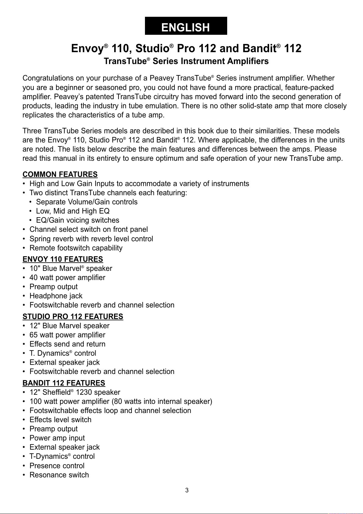
Inputs
The inputs of your TransTube Series amplifier are tailored to respond exactly like the inputs found
on popular tube amplifiers. Always use quality, shielded instrument cables when connecting your
instrument to the input.
4. High Gain Input
This is the standard input used for most instrument applications. Most electric guitars will
work ideally when plugged into this 1/4" mono input. The High Gain Input is 6 dB louder than
the Low Gain Input (5).
5. Low Gain Input
This 1/4" mono input is provided for instruments with extremely high outputs, which can result
in overdriving (distorting) the High Gain Input (4). If both the Low Gain and High Gain inputs
are used simultaneously, their levels are both Low Gain.
4
5
4
All manuals and user guides at all-guides.com
Page 5
CHANNELS
Your TransTube Series amp offers two-channel operation. Both the Clean and Lead channels
provide a flexible platform for you to establish your favorite tone. The footswitch (optional on Envoy
110 and Studio Pro 112) allows remote switching between the two channels and is explained in
detail on page 8 of this guide.
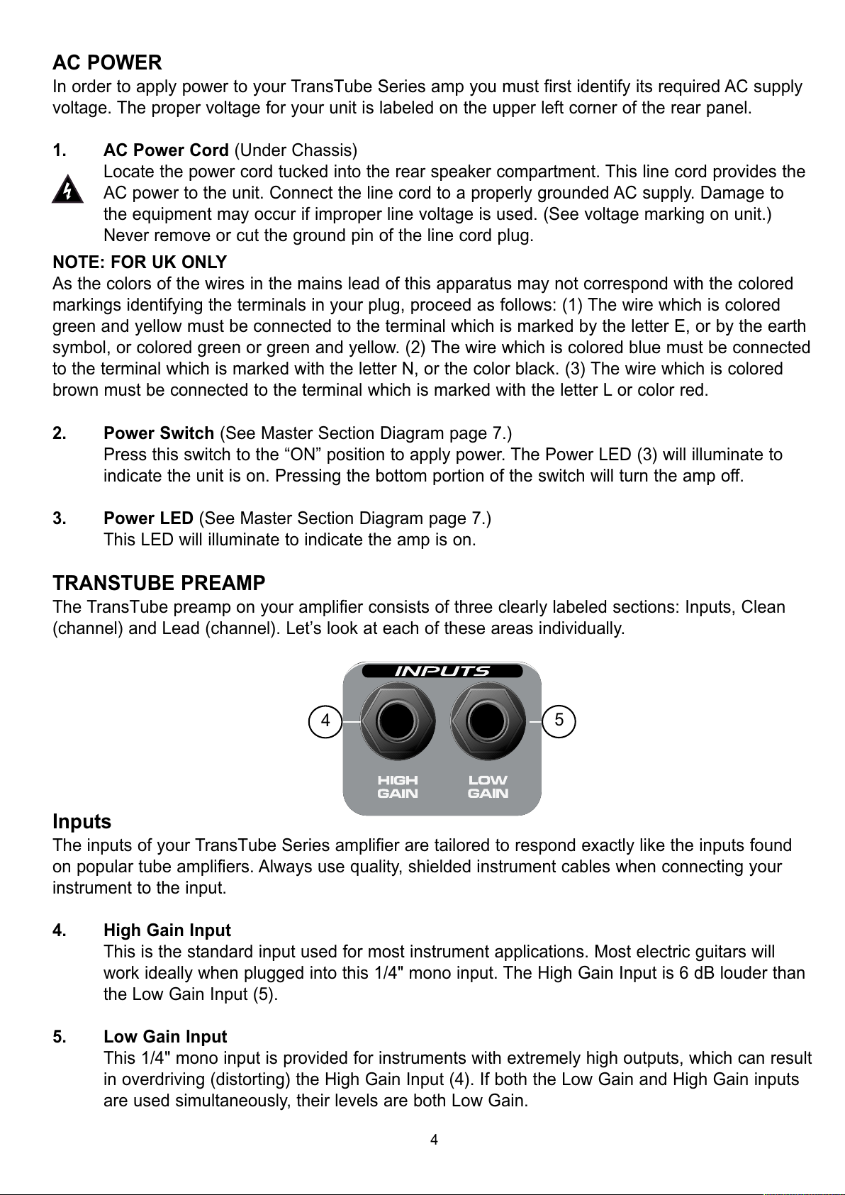
6. Channel Select Switch
The Channel Select Switch determines which channel of the TransTube Preamp, LEAD or
CLEAN, is active. This switch must be in the “LEAD” position in order for the footswitch
function of your amp to work.
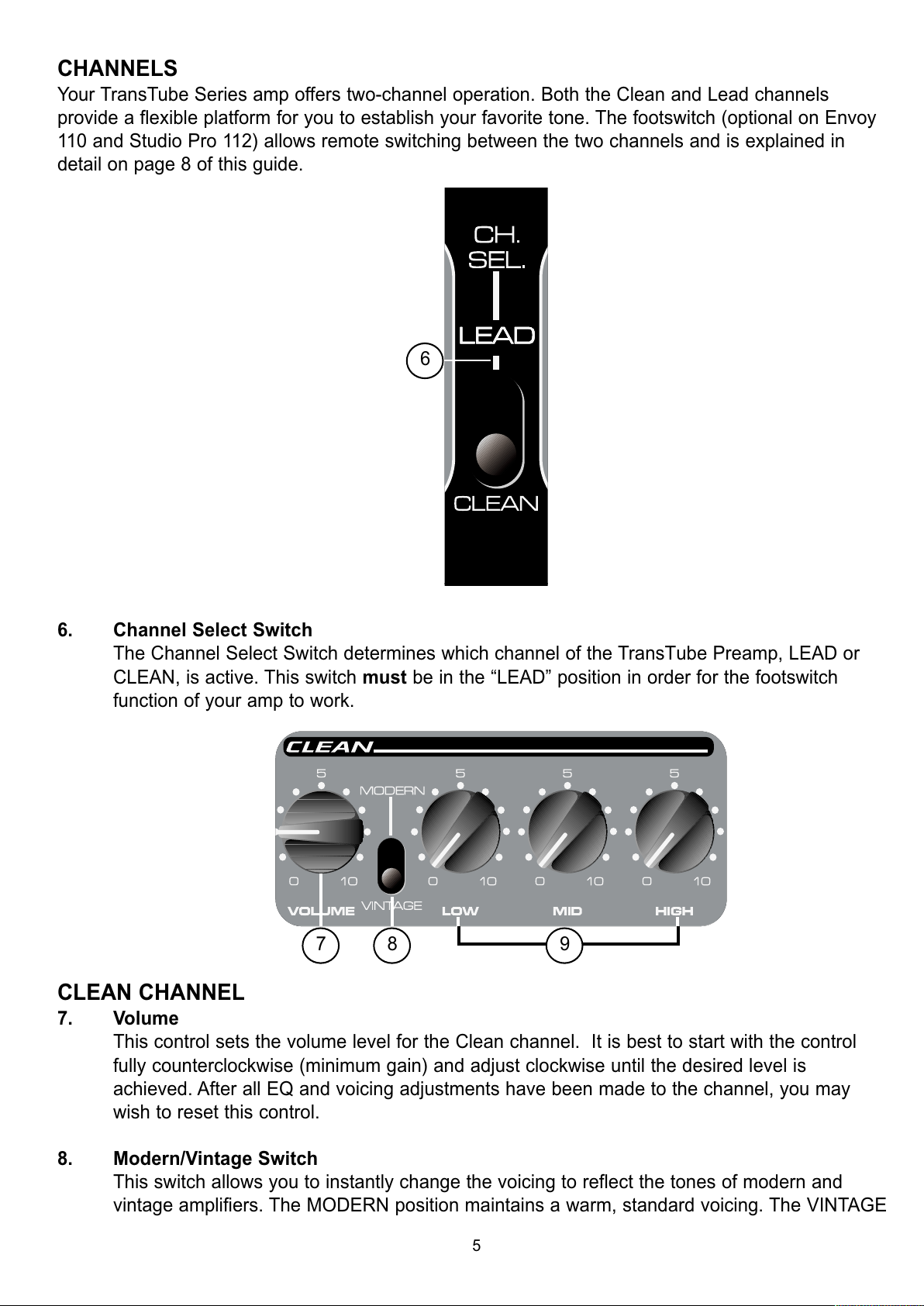
CLEAN CHANNEL
7. Volume
This control sets the volume level for the Clean channel. It is best to start with the control
fully counterclockwise (minimum gain) and adjust clockwise until the desired level is
achieved. After all EQ and voicing adjustments have been made to the channel, you may
wish to reset this control.
8. Modern/Vintage Switch
This switch allows you to instantly change the voicing to reflect the tones of modern and
vintage amplifiers. The MODERN position maintains a warm, standard voicing. The VINTAGE
5
6
7 8 9
All manuals and user guides at all-guides.com
Page 6
position changes the overall function of the EQ and adds a hint of brightness to emulate
some classic amp designs. Experiment with this switch, along with Clean EQ (9) adjustments,
to capture your desired tone. You may refer to the Recommended Settings on page 11 for
some creative starting points.
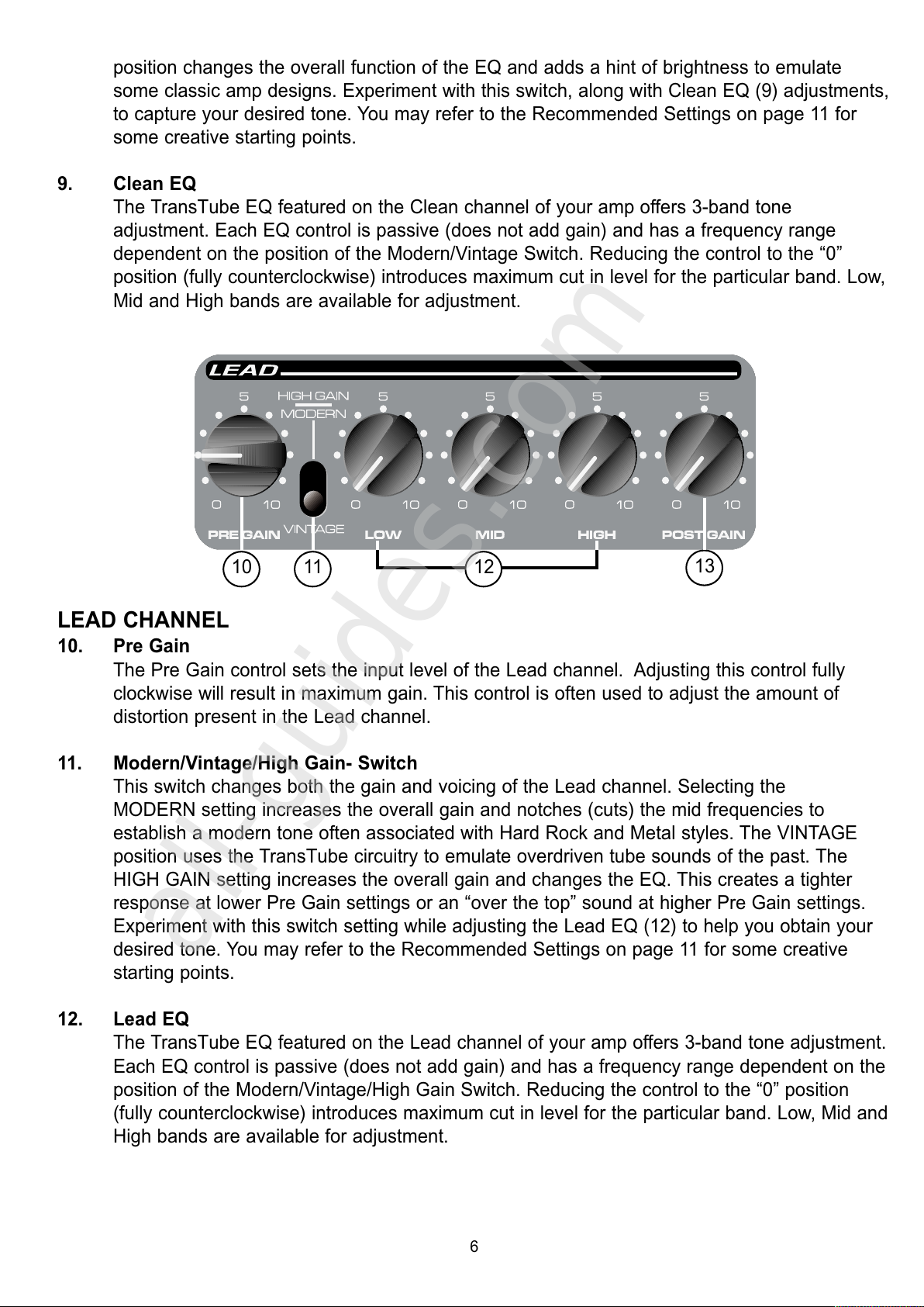
9. Clean EQ
The TransTube EQ featured on the Clean channel of your amp offers 3-band tone
adjustment. Each EQ control is passive (does not add gain) and has a frequency range
dependent on the position of the Modern/Vintage Switch. Reducing the control to the “0”
position (fully counterclockwise) introduces maximum cut in level for the particular band. Low,
Mid and High bands are available for adjustment.
LEAD CHANNEL
10. Pre Gain
The Pre Gain control sets the input level of the Lead channel. Adjusting this control fully
clockwise will result in maximum gain. This control is often used to adjust the amount of
distortion present in the Lead channel.
11. Modern/Vintage/High Gain- Switch
This switch changes both the gain and voicing of the Lead channel. Selecting the
MODERN setting increases the overall gain and notches (cuts) the mid frequencies to
establish a modern tone often associated with Hard Rock and Metal styles. The VINTAGE
position uses the TransTube circuitry to emulate overdriven tube sounds of the past. The
HIGH GAIN setting increases the overall gain and changes the EQ. This creates a tighter
response at lower Pre Gain settings or an “over the top” sound at higher Pre Gain settings.
Experiment with this switch setting while adjusting the Lead EQ (12) to help you obtain your
desired tone. You may refer to the Recommended Settings on page 11 for some creative
starting points.
12. Lead EQ
The TransTube EQ featured on the Lead channel of your amp offers 3-band tone adjustment.
Each EQ control is passive (does not add gain) and has a frequency range dependent on the
position of the Modern/Vintage/High Gain Switch. Reducing the control to the “0” position
(fully counterclockwise) introduces maximum cut in level for the particular band. Low, Mid and
High bands are available for adjustment.
6
10 11
13
12
All manuals and user guides at all-guides.com
all-guides.com
Page 7
13. Post Gain
Use this control to set the overall level of the Lead channel once your tone has been
achieved. It is best to start with the control fully counterclockwise (minimum gain) and adjust
clockwise until the desired level is achieved. After all EQ and voicing adjustments have been
made to the channel, you may wish to reset this control.
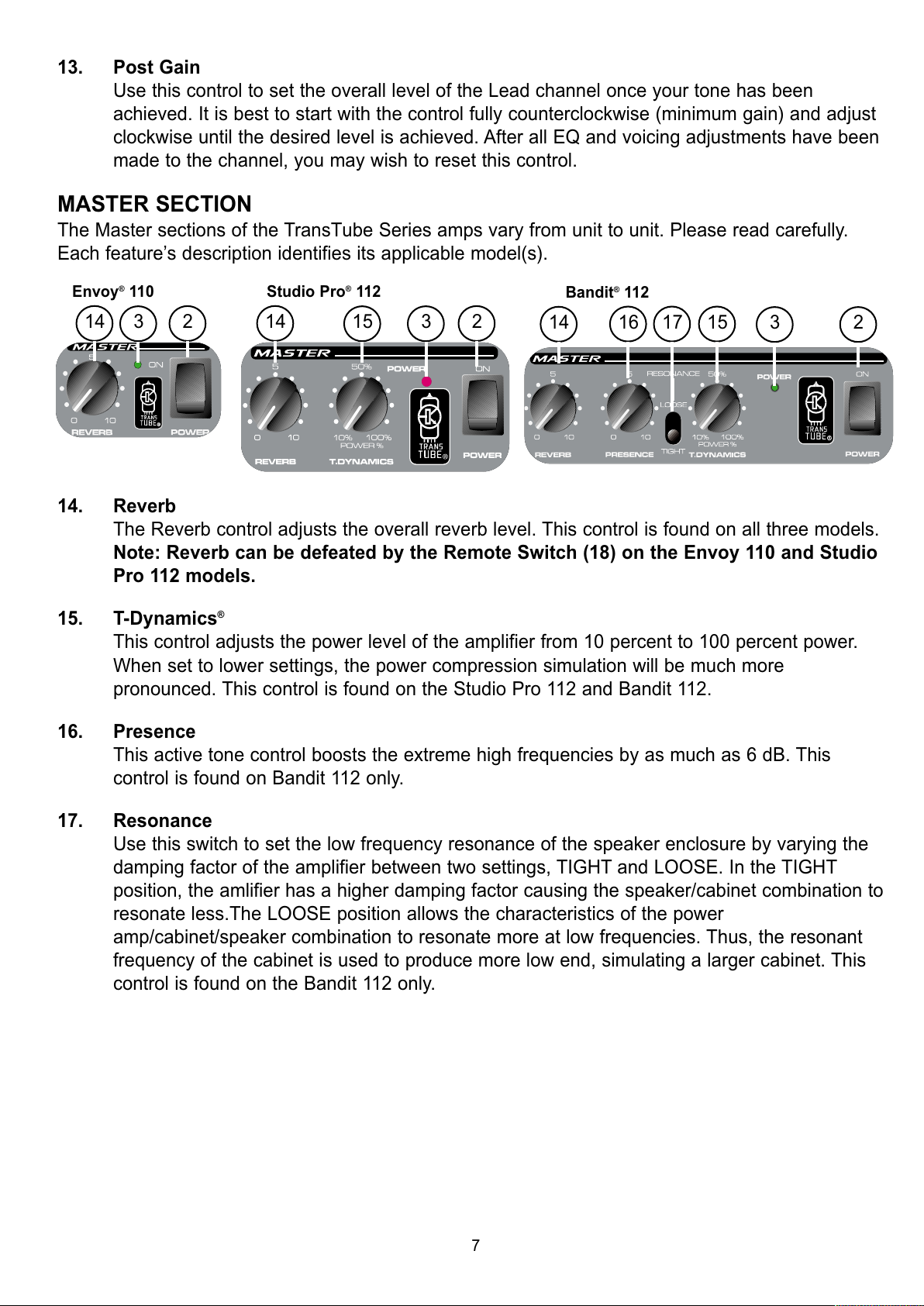
MASTER SECTION
The Master sections of the TransTube Series amps vary from unit to unit. Please read carefully.
Each feature’s description identifies its applicable model(s).
14. Reverb
The Reverb control adjusts the overall reverb level. This control is found on all three models.
Note: Reverb can be defeated by the Remote Switch (18) on the Envoy 110 and Studio
Pro 112 models.
15. T-Dynamics
®
This control adjusts the power level of the amplifier from 10 percent to 100 percent power.
When set to lower settings, the power compression simulation will be much more
pronounced. This control is found on the Studio Pro 112 and Bandit 112.
16. Presence
This active tone control boosts the extreme high frequencies by as much as 6 dB. This
control is found on Bandit 112 only.
17. Resonance
Use this switch to set the low frequency resonance of the speaker enclosure by varying the
damping factor of the amplifier between two settings, TIGHT and LOOSE. In the TIGHT
position, the amlifier has a higher damping factor causing the speaker/cabinet combination to
resonate less.The LOOSE position allows the characteristics of the power
amp/cabinet/speaker combination to resonate more at low frequencies. Thus, the resonant
frequency of the cabinet is used to produce more low end, simulating a larger cabinet. This
control is found on the Bandit 112 only.
7
14
3
2
Envoy®110
14
3
15
2
Studio Pro®112
14
3
16 17 15
2
Bandit®112
All manuals and user guides at all-guides.com
Page 8
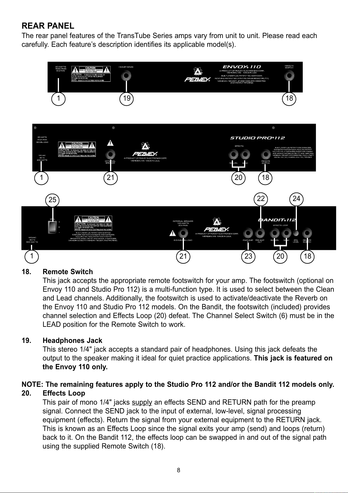
REAR PANEL
The rear panel features of the TransTube Series amps vary from unit to unit. Please read each
carefully. Each feature’s description identifies its applicable model(s).
18. Remote Switch
This jack accepts the appropriate remote footswitch for your amp. The footswitch (optional on
Envoy 110 and Studio Pro 112) is a multi-function type. It is used to select between the Clean
and Lead channels. Additionally, the footswitch is used to activate/deactivate the Reverb on
the Envoy 110 and Studio Pro 112 models. On the Bandit, the footswitch (included) provides
channel selection and Effects Loop (20) defeat. The Channel Select Switch (6) must be in the
LEAD position for the Remote Switch to work.
19. Headphones Jack
This stereo 1/4" jack accepts a standard pair of headphones. Using this jack defeats the
output to the speaker making it ideal for quiet practice applications. This jack is featured on
the Envoy 110 only.
NOTE: The remaining features apply to the Studio Pro 112 and/or the Bandit 112 models only.
20. Effects Loop
This pair of mono 1/4" jacks supply
an effects SEND and RETURN path for the preamp
signal. Connect the SEND jack to the input of external, low-level, signal processing
equipment (effects). Return the signal from your external equipment to the RETURN jack.
This is known as an Effects Loop since the signal exits your amp (send) and loops (return)
back to it. On the Bandit 112, the effects loop can be swapped in and out of the signal path
using the supplied Remote Switch (18).
21 1820
19
1
1
18
8
21 23 18
24
22
20
1
25
All manuals and user guides at all-guides.com
Page 9
21. External Speaker Jack
This 1/4" jack is provided for the connection of an external speaker cabinet such as the
Peavey 412M. The minimum external speaker impedance is 8 ohms. This jack disconnects
internal speaker when used on Studio Pro 112
NOTE: The remaining features apply to the Bandit 112 model only.
22. Preamp Out
The Preamp Output can be used to route the preamp signal to a mixing console, tape
recorder, etc. Using a shielded instrument cable with mono 1/4" plugs, connect the Preamp
Output to the input of your outboard equipment. This patch will not affect the normal operation
of your amplifier.
23. Power Amp In
Connect line level signals from external equipment to this input. Inserting a plug into this
mono 1/4" jack will prevent the TransTube preamp signal from being sent to the amplifier.
In this configuration, the power amp only amplifies the signal introduced at the Power Amp
In jack.
24. Effects Level
This switch selects the Effects Loop (20) operating level. When the switch is pressed to the
“in” position the level is set for 0 dBV (1 V RMS). Placing the switch to the “out” position
changes the level to -10 dBV (0.3 V RMS). Refer to the owner’s manual for your external
effects to determine the correct position for this switch.
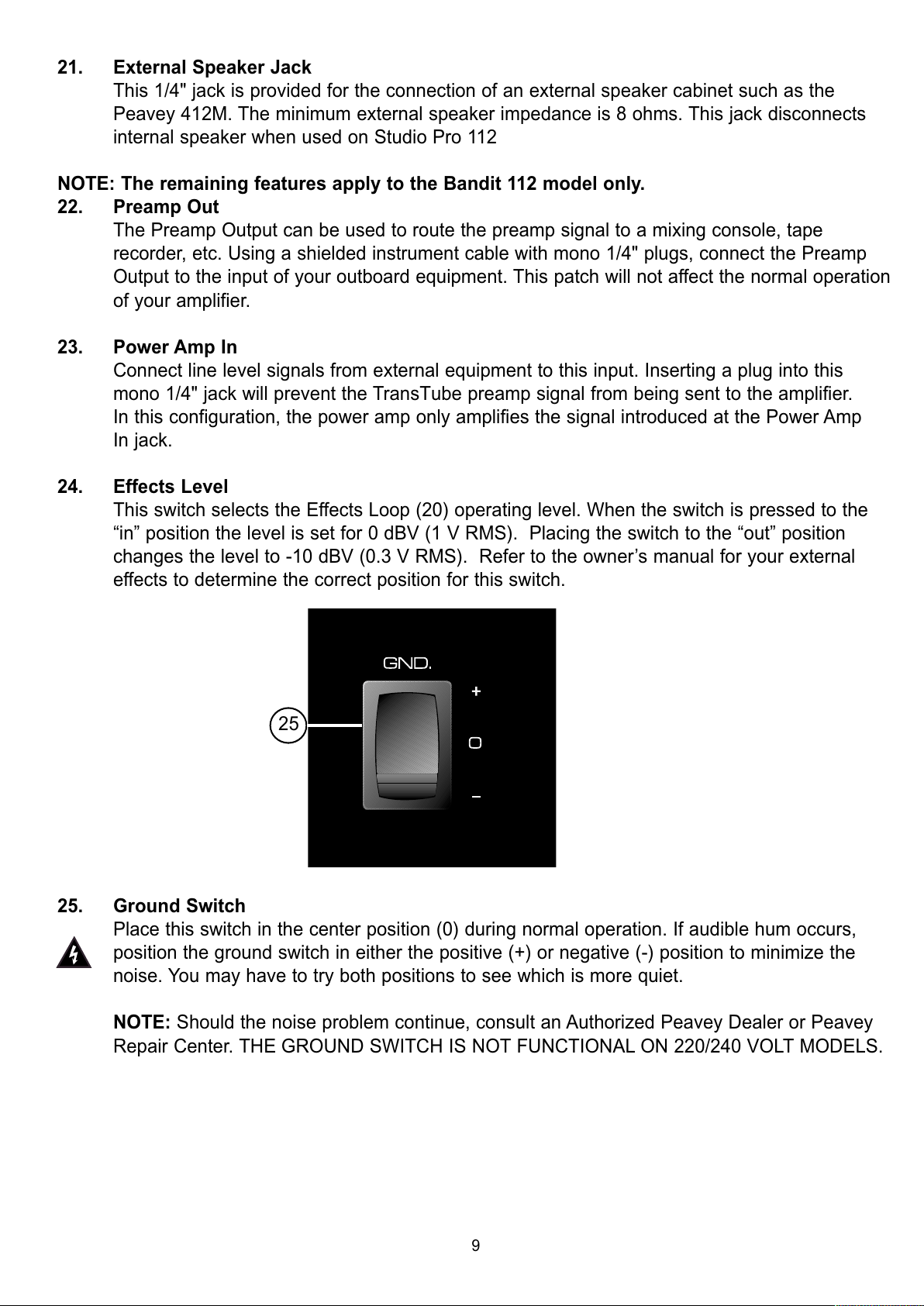
25. Ground Switch
Place this switch in the center position (0) during normal operation. If audible hum occurs,
position the ground switch in either the positive (+) or negative (-) position to minimize the
noise. You may have to try both positions to see which is more quiet.
NOTE: Should the noise problem continue, consult an Authorized Peavey Dealer or Peavey
Repair Center. THE GROUND SWITCH IS NOT FUNCTIONAL ON 220/240 VOLT MODELS.
25
9
All manuals and user guides at all-guides.com
Page 10
REVERB
REVERB
FOOT
SWITCH
LEVEL
EFFECTS
SEND RETURN
FOOT
SWITCH
SWITCH
LOGIC
VINTAGE MODERN
VOLUME
CLEAN
FOOT
SWITCH
INPUTS
SWITCH
LOGIC
VINTAGE MODERN
HI
GAIN
PRE
LO MID HI
LO MID HI
EQUALIZATION
LEAD
POST
T. D YNAMICS
POWER
AMP
12"
SPEAKER
EXT.
SPEAKER
10"
SPEAKER
HEADPHONES
ENVOY
®
STUDIO PRO
®
REVERB
LEVEL
BYPASS
EFFECTS
SEND RETURN
FOOT
SWITCH
PRE
OUT
PWR
IN
RESONANCE
PRESENCE
POWER
AMP
12"
SPEAKER
EXT.
SPEAKER
LEVEL
POWER
AMP
BANDIT
®
SWITCH
LOGIC
T. D YNAMICS
10
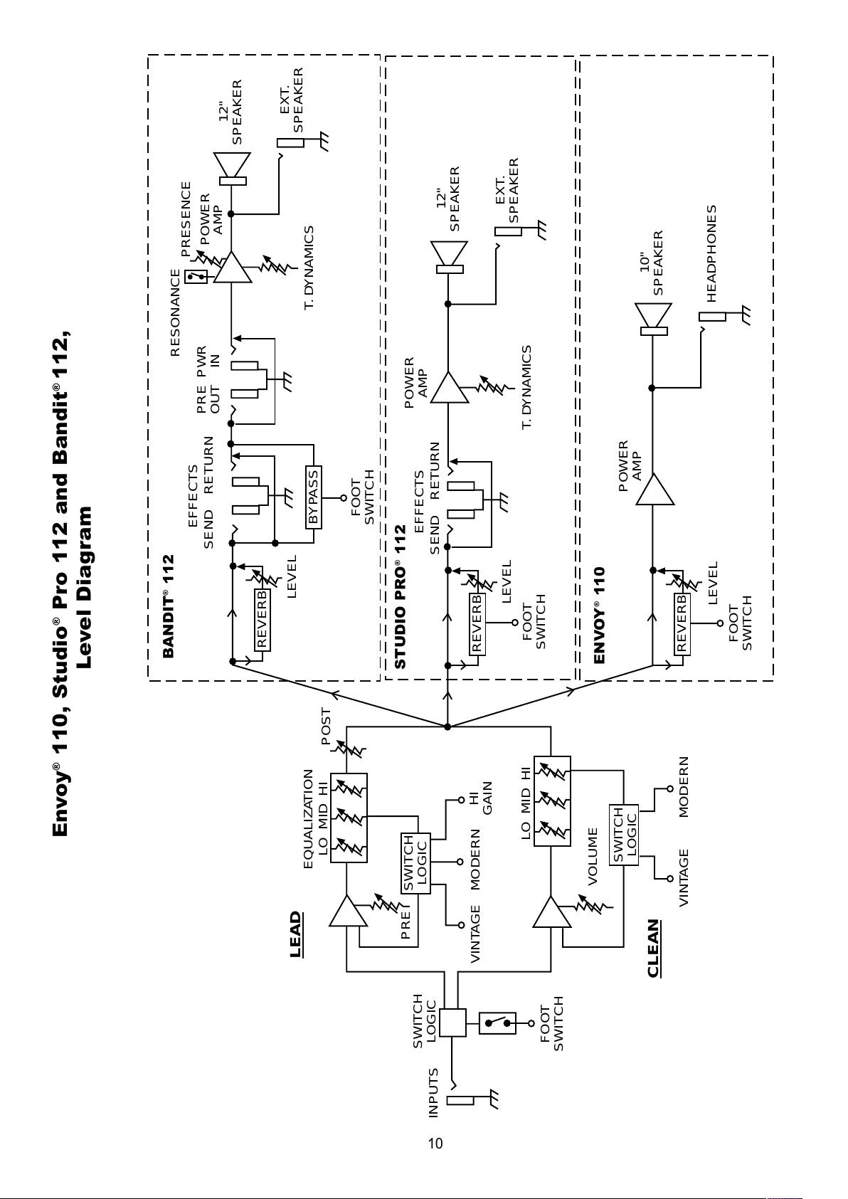
Envoy
®
110, Studio
®
Pro 112 and Bandit
®
112,
Level Diagram
BANDIT
®
112
STUDIO PRO
®
112
ENVOY
®
110
All manuals and user guides at all-guides.com
Page 11
11
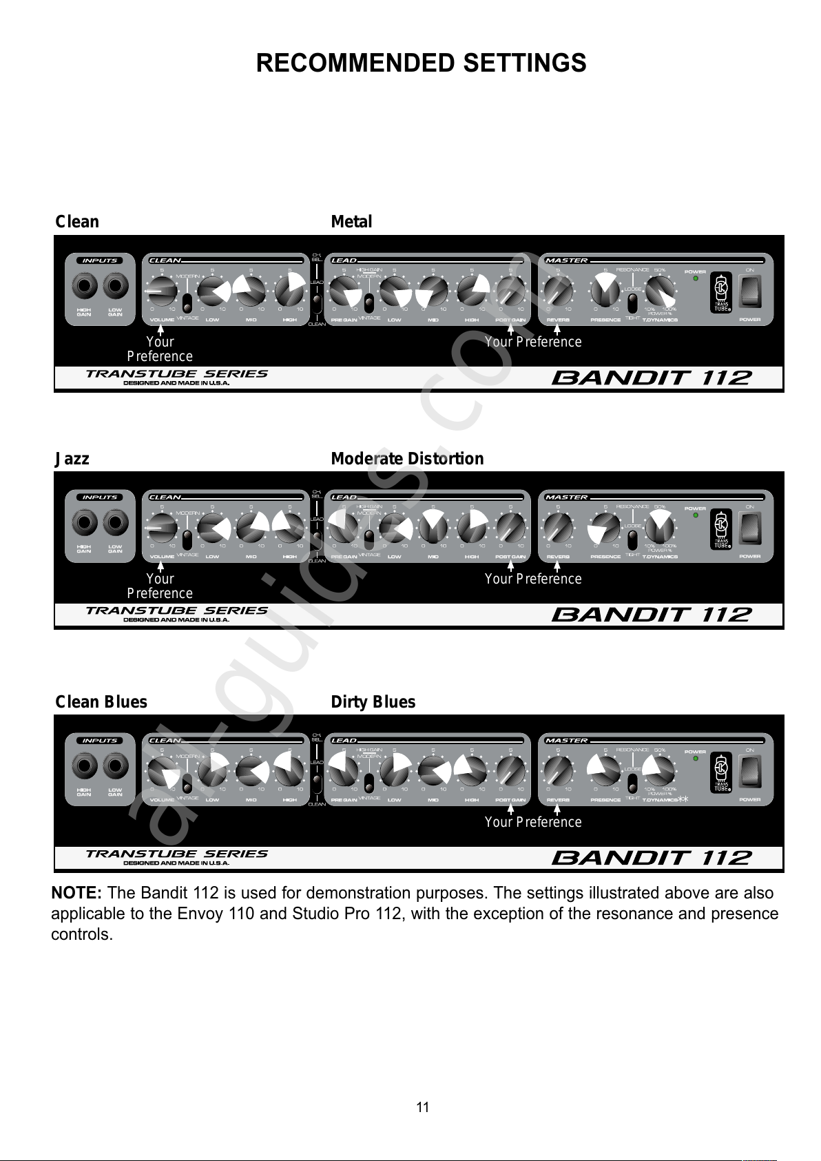
Clean Metal
Clean Blues Dirty Blues
Your Preference
**
Jazz Moderate Distortion
Your
Preference
Your Preference
Your
Preference
Your Preference
RECOMMENDED SETTINGS
NOTE: The Bandit 112 is used for demonstration purposes. The settings illustrated above are also
applicable to the Envoy 110 and Studio Pro 112, with the exception of the resonance and presence
controls.
All manuals and user guides at all-guides.com
all-guides.com
Page 12
Specifications subject to change without notice.
12
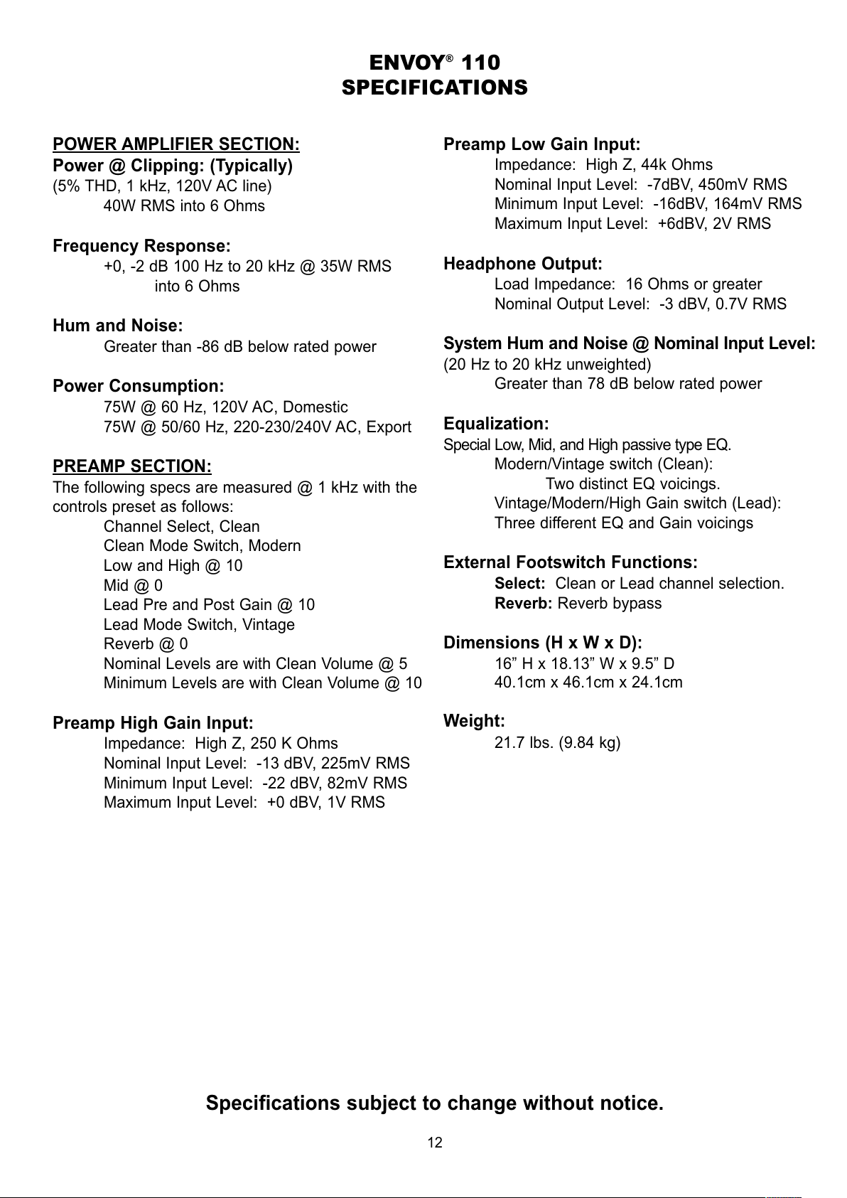
POWER AMPLIFIER SECTION:
Power @ Clipping: (Typically)
(5% THD, 1 kHz, 120V AC line)
40W RMS into 6 Ohms
Frequency Response:
+0, -2 dB 100 Hz to 20 kHz @ 35W RMS
into 6 Ohms
Hum and Noise:
Greater than -86 dB below rated power
Power Consumption:
75W @ 60 Hz, 120V AC, Domestic
75W @ 50/60 Hz, 220-230/240V AC, Export
PREAMP
SECTION:
The following specs are measured @ 1 kHz with the
controls preset as follows:
Channel Select, Clean
Clean Mode Switch, Modern
Low and High @ 10
Mid @ 0
Lead Pre and Post Gain @ 10
Lead Mode Switch, Vintage
Reverb @ 0
Nominal Levels are with Clean Volume @ 5
Minimum Levels are with Clean Volume @ 10
Preamp High Gain Input:
Impedance: High Z, 250 K Ohms
Nominal Input Level: -13 dBV, 225mV RMS
Minimum Input Level: -22 dBV, 82mV RMS
Maximum Input Level: +0 dBV, 1V RMS
Preamp Low Gain Input:
Impedance: High Z, 44k Ohms
Nominal Input Level: -7dBV, 450mV RMS
Minimum Input Level: -16dBV, 164mV RMS
Maximum Input Level: +6dBV, 2V RMS
Headphone Output:
Load Impedance: 16 Ohms or greater
Nominal Output Level: -3 dBV, 0.7V RMS
System Hum and Noise @ Nominal Input Level:
(20 Hz to 20 kHz unweighted)
Greater than 78 dB below rated power
Equalization:
Special Low, Mid, and High passive type EQ.
Modern/Vintage switch (Clean):
Two distinct EQ voicings.
Vintage/Modern/High Gain switch (Lead):
Three different EQ and Gain voicings
External Footswitch Functions:
Select: Clean or Lead channel selection.
Reverb: Reverb bypass
Dimensions (H x W x D):
16” H x 18.13” W x 9.5” D
40.1cm x 46.1cm x 24.1cm
Weight:
21.7 lbs. (9.84 kg)
ENVOY®110
SPECIFICATIONS
All manuals and user guides at all-guides.com
Page 13
Specifications subject to change without notice.
13
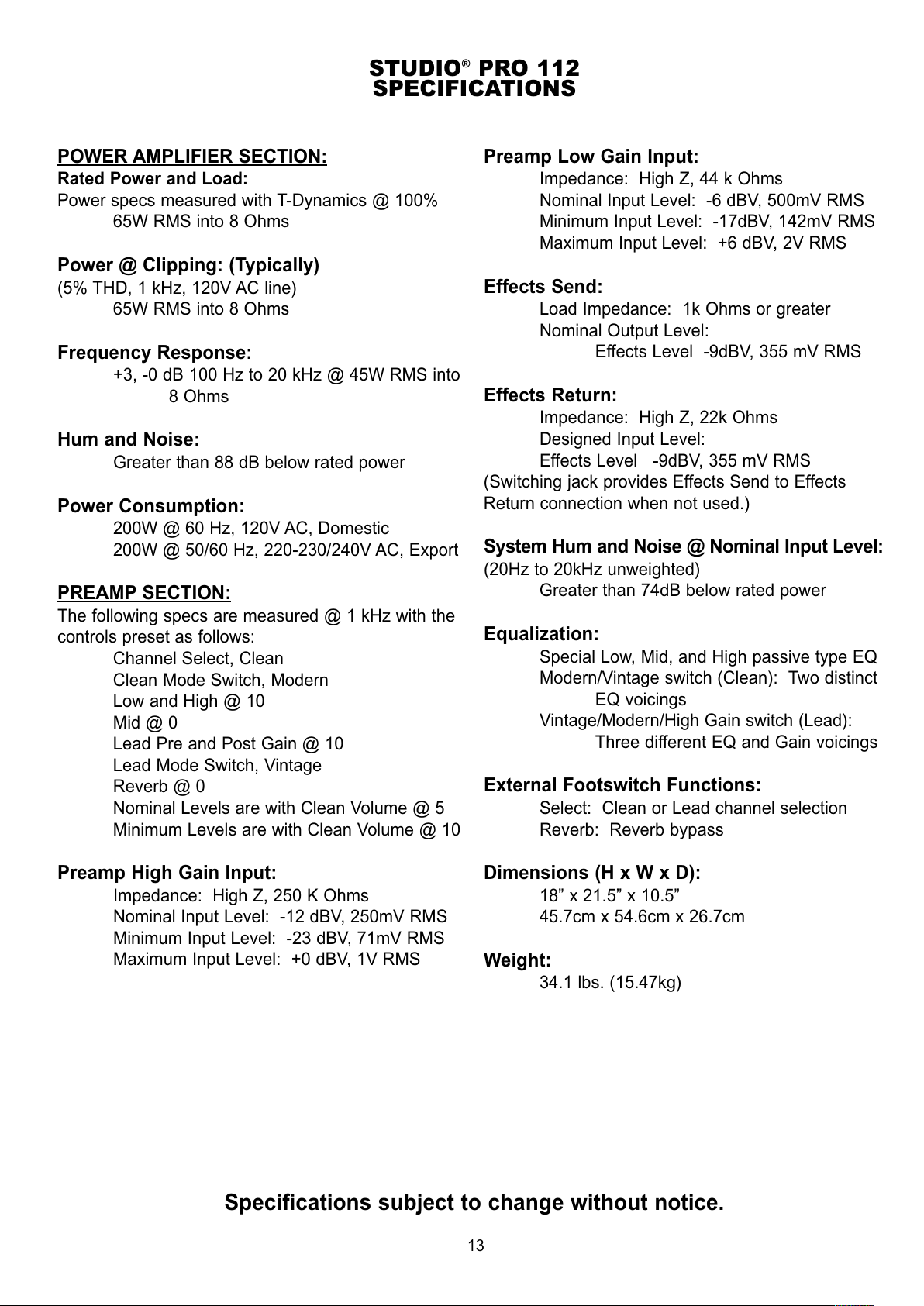
POWER AMPLIFIER SECTION:
Rated Power and Load:
Power specs measured with T-Dynamics @ 100%
65W RMS into 8 Ohms
Power @ Clipping: (Typically)
(5% THD, 1 kHz, 120V AC line)
65W RMS into 8 Ohms
Frequency Response:
+3, -0 dB 100 Hz to 20 kHz @ 45W RMS into
8 Ohms
Hum and Noise:
Greater than 88 dB below rated power
Power Consumption:
200W @ 60 Hz, 120V AC, Domestic
200W @ 50/60 Hz, 220-230/240V AC, Export
PREAMP SECTION:
The following specs are measured @ 1 kHz with the
controls preset as follows:
Channel Select, Clean
Clean Mode Switch, Modern
Low and High @ 10
Mid @ 0
Lead Pre and Post Gain @ 10
Lead Mode Switch, Vintage
Reverb @ 0
Nominal Levels are with Clean Volume @ 5
Minimum Levels are with Clean Volume @ 10
Preamp High Gain Input:
Impedance: High Z, 250 K Ohms
Nominal Input Level: -12 dBV, 250mV RMS
Minimum Input Level: -23 dBV, 71mV RMS
Maximum Input Level: +0 dBV, 1V RMS
Preamp Low Gain Input:
Impedance: High Z, 44 k Ohms
Nominal Input Level: -6 dBV, 500mV RMS
Minimum Input Level: -17dBV, 142mV RMS
Maximum Input Level: +6 dBV, 2V RMS
Effects Send:
Load Impedance: 1k Ohms or greater
Nominal Output Level:
Effects Level -9dBV, 355 mV RMS
Effects Return:
Impedance: High Z, 22k Ohms
Designed Input Level:
Effects Level -9dBV, 355 mV RMS
(Switching jack provides Effects Send to Effects
Return connection when not used.)
System Hum and Noise @ Nominal Input Level:
(20Hz to 20kHz unweighted)
Greater than 74dB below rated power
Equalization:
Special Low, Mid, and High passive type EQ
Modern/Vintage switch (Clean): Two distinct
EQ voicings
Vintage/Modern/High Gain switch (Lead):
Three different EQ and Gain voicings
External Footswitch Functions:
Select: Clean or Lead channel selection
Reverb: Reverb bypass
Dimensions (H x W x D):
18” x 21.5” x 10.5”
45.7cm x 54.6cm x 26.7cm
Weight:
34.1 lbs. (15.47kg)
STUDIO®PRO 112
SPECIFICATIONS
All manuals and user guides at all-guides.com
Page 14
14
Specifications subject to change without notice.
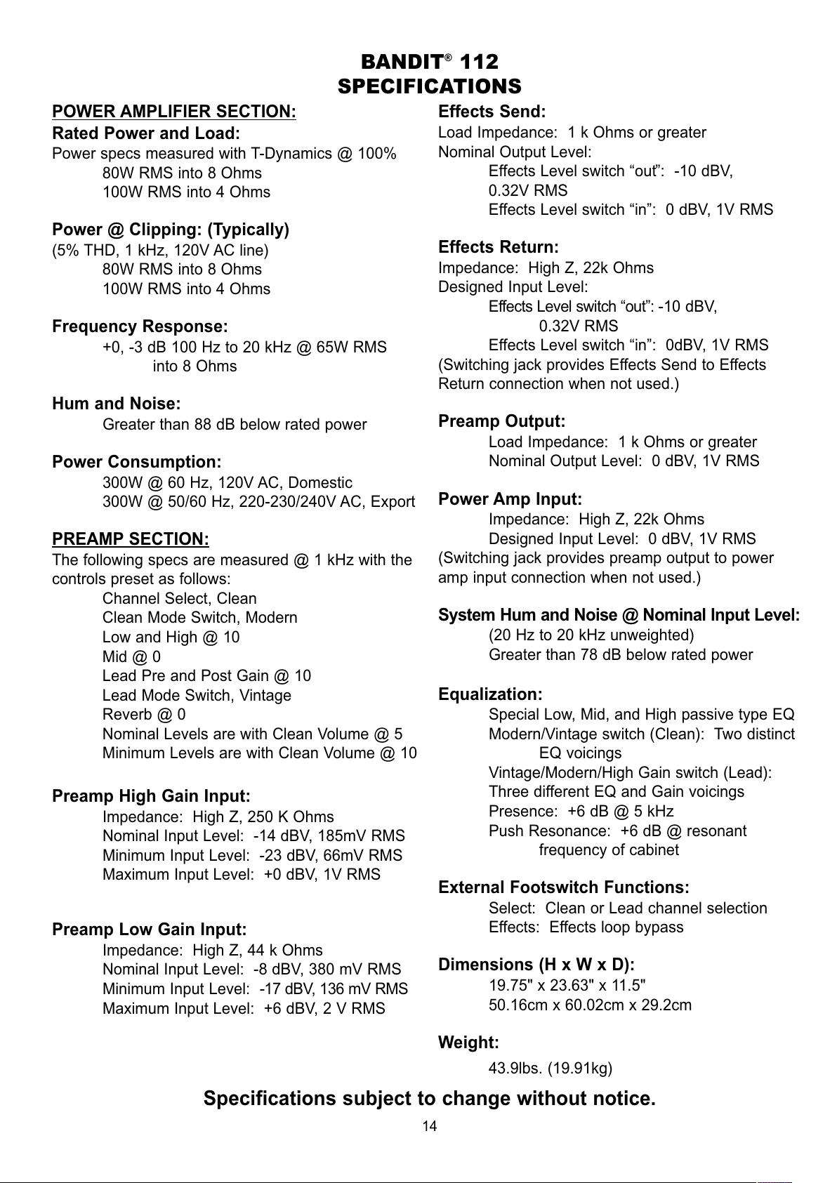
POWER AMPLIFIER SECTION:
Rated Power and Load:
Power specs measured with T-Dynamics @ 100%
80W RMS into 8 Ohms
100W RMS into 4 Ohms
Power @ Clipping: (Typically)
(5% THD, 1 kHz, 120V AC line)
80W RMS into 8 Ohms
100W RMS into 4 Ohms
Frequency Response:
+0, -3 dB 100 Hz to 20 kHz @ 65W RMS
into 8 Ohms
Hum and Noise:
Greater than 88 dB below rated power
Power Consumption:
300W @ 60 Hz, 120V AC, Domestic
300W @ 50/60 Hz, 220-230/240V AC, Export
PREAMP SECTION:
The following specs are measured @ 1 kHz with the
controls preset as follows:
Channel Select, Clean
Clean Mode Switch, Modern
Low and High @ 10
Mid @ 0
Lead Pre and Post Gain @ 10
Lead Mode Switch, Vintage
Reverb @ 0
Nominal Levels are with Clean Volume @ 5
Minimum Levels are with Clean Volume @ 10
Preamp High Gain Input:
Impedance: High Z, 250 K Ohms
Nominal Input Level: -14 dBV, 185mV RMS
Minimum Input Level: -23 dBV, 66mV RMS
Maximum Input Level: +0 dBV, 1V RMS
Preamp Low Gain Input:
Impedance: High Z, 44 k Ohms
Nominal Input Level: -8 dBV, 380 mV RMS
Minimum Input Level: -17 dBV, 136 mV RMS
Maximum Input Level: +6 dBV, 2 V RMS
Effects Send:
Load Impedance: 1 k Ohms or greater
Nominal Output Level:
Effects Level switch “out”: -10 dBV,
0.32V RMS
Effects Level switch “in”: 0 dBV, 1V RMS
Effects Return:
Impedance: High Z, 22k Ohms
Designed Input Level:
Effects Level switch “out”: -10 dBV,
0.32V RMS
Effects Level switch “in”: 0dBV, 1V RMS
(Switching jack provides Effects Send to Effects
Return connection when not used.)
Preamp Output:
Load Impedance: 1 k Ohms or greater
Nominal Output Level: 0 dBV, 1V RMS
Power Amp Input:
Impedance: High Z, 22k Ohms
Designed Input Level: 0 dBV, 1V RMS
(Switching jack provides preamp output to power
amp input connection when not used.)
System Hum and Noise @ Nominal Input Level:
(20 Hz to 20 kHz unweighted)
Greater than 78 dB below rated power
Equalization:
Special Low, Mid, and High passive type EQ
Modern/Vintage switch (Clean): Two distinct
EQ voicings
Vintage/Modern/High Gain switch (Lead):
Three different EQ and Gain voicings
Presence: +6 dB @ 5 kHz
Push Resonance: +6 dB @ resonant
frequency of cabinet
External Footswitch Functions:
Select: Clean or Lead channel selection
Effects: Effects loop bypass
Dimensions (H x W x D):
19.75" x 23.63" x 11.5"
50.16cm x 60.02cm x 29.2cm
Weight:
43.9lbs. (19.91kg)
BANDIT®112
SPECIFICATIONS
All manuals and user guides at all-guides.com
Page 15
15
ESPAÑOL
Envoy®110, Studio Pro®112 y Bandit®112
de la Serie Transtube®de
Amplificadores para Instrumentos
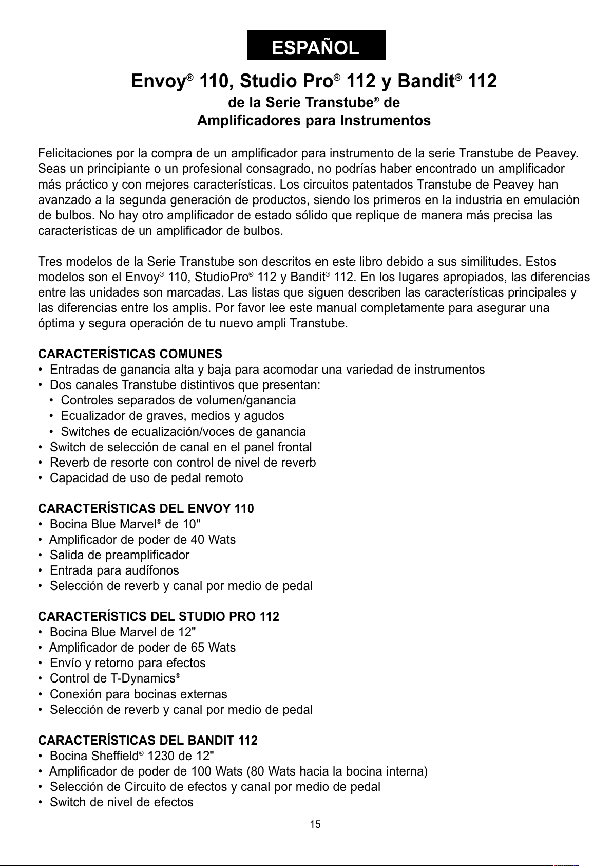
Felicitaciones por la compra de un amplificador para instrumento de la serie Transtube de Peavey.
Seas un principiante o un profesional consagrado, no podrías haber encontrado un amplificador
más práctico y con mejores características. Los circuitos patentados Transtube de Peavey han
avanzado a la segunda generación de productos, siendo los primeros en la industria en emulación
de bulbos. No hay otro amplificador de estado sólido que replique de manera más precisa las
características de un amplificador de bulbos.
Tres modelos de la Serie Transtube son descritos en este libro debido a sus similitudes. Estos
modelos son el Envoy
®
110, StudioPro®112 y Bandit®112. En los lugares apropiados, las diferencias
entre las unidades son marcadas. Las listas que siguen describen las características principales y
las diferencias entre los amplis. Por favor lee este manual completamente para asegurar una
óptima y segura operación de tu nuevo ampli Transtube.
CARACTERÍSTICAS COMUNES
• Entradas de ganancia alta y baja para acomodar una variedad de instrumentos
• Dos canales Transtube distintivos que presentan:
• Controles separados de volumen/ganancia
• Ecualizador de graves, medios y agudos
• Switches de ecualización/voces de ganancia
• Switch de selección de canal en el panel frontal
• Reverb de resorte con control de nivel de reverb
• Capacidad de uso de pedal remoto
CARACTERÍSTICAS DEL ENVOY 110
• Bocina Blue Marvel
®
de 10"
• Amplificador de poder de 40 Wats
• Salida de preamplificador
• Entrada para audífonos
• Selección de reverb y canal por medio de pedal
CARACTERÍSTICS DEL STUDIO PRO 112
• Bocina Blue Marvel de 12"
• Amplificador de poder de 65 Wats
• Envío y retorno para efectos
• Control de T-Dynamics
®
• Conexión para bocinas externas
• Selección de reverb y canal por medio de pedal
CARACTERÍSTICAS DEL BANDIT 112
• Bocina Sheffield
®
1230 de 12"
• Amplificador de poder de 100 Wats (80 Wats hacia la bocina interna)
• Selección de Circuito de efectos y canal por medio de pedal
• Switch de nivel de efectos
All manuals and user guides at all-guides.com
Page 16

• Salida de preamplificador
• Entrada para amplificador de poder
• Conexión para bocinas externas
• Control T-Dynamics
®
• Control de presencia
PODER DE CORRIENTE ALTERNA
Para poder aplicar poder a tu amplificador de la Serie Transtube, primero debes identificar su
suministro de voltaje de CA. El voltaje apropiado para tu unidad está rotulado en la esquina superior
izquierda del panel trasero.
1. Cable de Poder de CA (Debajo del Chasis)
Localiza el cable de poder que está guardado en el compartimento de bocina trasero. Este
cable suministra el poder de CA a la unidad. Conecta el cable a un suministro de CA
propiamente aterrizado. El equipo puede ser dañado si se usa un voltaje de línea incorrecto
(ver marcación de voltaje en la unidad). Nunca quites o cortes la aguja de tierra del conector
del cable.
2. Switch de Poder (Ver diagrama de la Sección Maestra en la página 7)
Oprime el switch a la posición "ON" para aplicar poder. El LED de poder (3) se iluminará para
indicar que la unidad está encendida. El oprimir la porción inferior del switch apagará el
amplificador.
3. LED de Poder (ver diagrama de la Sección Maestra en la página 7)
LED se iluminará para indicar que el ampli está encendido.
PREAMPLIFICADOR TRANSTUBE
El preamplificador Transtube de tu amplificador consiste de tres secciones claramente rotuladas:
Inputs, Clean (limpio) y Lead. Veamos cada una de estas áreas individualmente.
Entradas
Las entradas de tu amplificador de la Serie Transtube están diseñadas para responder exactamente
como las entradas de los amplificadores de bulbos populares. Siempre usa cables protegidos de
calidad cuando conectes tu instrumento a la entrada.
4. Entrada de Alta Ganancia
Ésta es la entrada estándar usada para la mayoría de las aplicaciones con instrumento. La
mayoría de las guitarras eléctricas funcionarán de manera óptima al conectarlas a esta
entrada monofónica de un 1/4". La entrada de alta ganancia es 6 dB más fuerte que la
entrada de baja ganancia (5).
5
4
16
All manuals and user guides at all-guides.com
all-guides.com
Page 17

5. Entrada de Baja Ganancia
Esta entrada monofónica de 1/4" se incluye para instrumentos con salidas extremadamente
altas, lo que puede resultar en una distorsión de la entrada de alta ganancia (4). Si se usan
simultáneamente las entradas de alta y baja ganancia, los niveles de ambas son de baja
ganancia.
CANAL
Tu ampli de la Serie Transtube ofrece operación a dos canales. Tanto el canal ‘clean’ como el ‘lead’
proveen una plataforma flexible para que establezcas tu tono favorito. El pedal (opcional en el
Envoy 110 y Studio Pro 112) te permite controlar los dos canales de manera remota y es explicado
en detalle en la página 8 de esta guía.
6. Switch de Selección de Canal
El switch de Selección de Canal determina qué canal del preampli Transtube, LEAD o
CLEAN, está activo. Este switch debe estar en la posición “LEAD” para que la función del
pedal de tu ampli funcione.
CANAL LIMPIO (CLEAN)
7. Volumen
Este control ajusta el nivel de volumen para el canal limpio. Lo más recomendable es
empezar con el control girado totalmente hacia la izquierda (ganancia mínima) y ajustarlo
6
7 8 9
17
All manuals and user guides at all-guides.com
Page 18
hacia la derecha hasta lograr el nivel deseado. Después de hacer todos los ajustes de
ecualización y voces en el canal, tal vez querrás reajustar este control.
8. Switch Modern/Vintage
Este switch te permite cambiar instantáneamente el tono para emular amplificadores
modernos y clásicos. La posición MODERN mantiene un tono cálido y estándar. La posición
VINTAGE cambia la función general de la ecualización añadiendo algo de brillo y emulando
algunos diseños de amplis clásicos. Experimenta con este switch, junto con ajustes de
ecualización limpia (9), para capturar tu tono deseado. Puedes referirte a los Ajustes
Recomendados de la página 11 para obtener algunos puntos de partida creativos.
9. Ecualización Limpia
El ecualizador Transtube en el canal limpio de tu ampli ofrece ajuste de tono a tres bandas.
Cada control de ecualización es pasivo (no ofrece ganancia) y tiene un rango de frecuencia
que depende de la posición del switch Modern/Vintage. Si reduces el control a la posición “0”
(totalmente hacia la izquierda) introducirás el máximo corte de nivel para esa banda en
particular. Están disponibles bandas para ajuste de graves, medios y agudos.
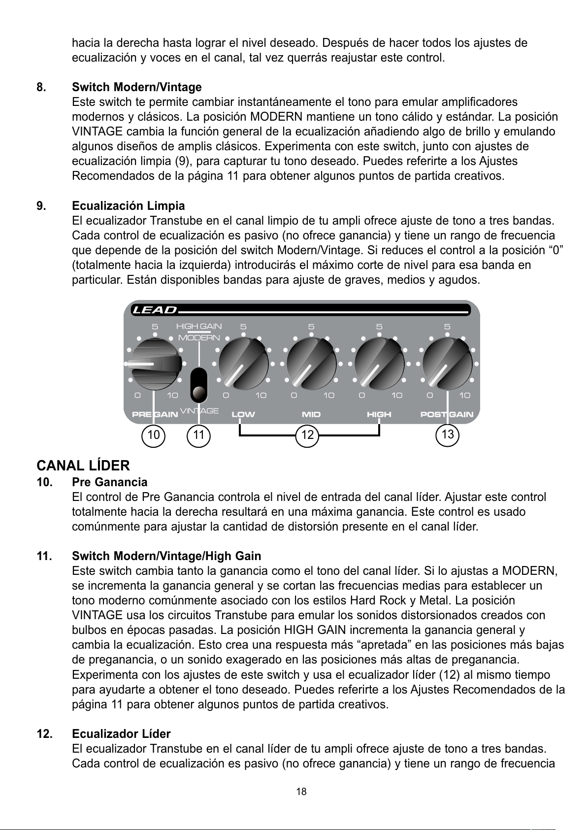
CANAL LÍDER
10. Pre Ganancia
El control de Pre Ganancia controla el nivel de entrada del canal líder. Ajustar este control
totalmente hacia la derecha resultará en una máxima ganancia. Este control es usado
comúnmente para ajustar la cantidad de distorsión presente en el canal líder.
11. Switch Modern/Vintage/High Gain
Este switch cambia tanto la ganancia como el tono del canal líder. Si lo ajustas a MODERN,
se incrementa la ganancia general y se cortan las frecuencias medias para establecer un
tono moderno comúnmente asociado con los estilos Hard Rock y Metal. La posición
VINTAGE usa los circuitos Transtube para emular los sonidos distorsionados creados con
bulbos en épocas pasadas. La posición HIGH GAIN incrementa la ganancia general y
cambia la ecualización. Esto crea una respuesta más “apretada” en las posiciones más bajas
de preganancia, o un sonido exagerado en las posiciones más altas de preganancia.
Experimenta con los ajustes de este switch y usa el ecualizador líder (12) al mismo tiempo
para ayudarte a obtener el tono deseado. Puedes referirte a los Ajustes Recomendados de la
página 11 para obtener algunos puntos de partida creativos.
12. Ecualizador Líder
El ecualizador Transtube en el canal líder de tu ampli ofrece ajuste de tono a tres bandas.
Cada control de ecualización es pasivo (no ofrece ganancia) y tiene un rango de frecuencia
10 11
13
12
18
All manuals and user guides at all-guides.com
Page 19

que depende de la posición del switch Modern/Vintage. Si reduces el control a la posición “0”
(totalmente hacia la izquierda) introducirás el máximo corte de nivel para esa banda en
particular. Están disponibles bandas para ajuste de graves, medios y agudos.
13. Post Ganancia
Usa este control para ajustar el nivel de canal líder una vez que tu tono haya sido logrado.
Lo más recomendable es empezar con el control totalmente hacia la izquierda y ajustarlo
hacia la derecha hasta alcanzar el nivel deseado. Después de hacer los ajustes de
ecualización y tono en el canal, puedes regresar este control a su posición original.
SECCIÓN MAESTRA
Las secciones maestras de los amplis de la Serie Transtube varían de unidad a unidad. Por favor
lee cuidadosamente la descripción de cada característica e identifica a los modelos aplicables.
14. Reverb
El control de reverb controla el nivel general de reverb. Este control se encuentra en los tres
modelos. Nota: El reverb puede ser cancelado con el switch remoto (18) en el Envoy 110 y
en el Studio Pro 112.
15. T-Dynamics
®
Este control ajusta el nivel de poder del amplificador de 10 a 100% de poder. Al ajustarse a
niveles menores, la simulación de compresión de poder será mucho más pronunciada. Este
control se encuentra en los modelos Studio Pro 112 y Bandit 112.
16. Presencia
Este control activo de tono aumenta las frecuencias extremadamente agudas hasta por 6 dB.
Este control sólo se encuentra en el Bandit 112.
17. Resonancia
Usa este switch para ajustar la resonancia de bajas frecuencias de la bocina variando el
factor de amortiguación del amplificador entre dos valores, TIGHT y LOOSE. En la posición
TIGHT el amplificador tiene un factor de amortiguación mayor causando que la combinación
bocina/gabinete tenga una menor resonancia. La posición LOOSE permite que las
características de la combinación ampli de poder/gabinete/bocina tengan mayor resonancia
en las frecuencias graves. Por lo tanto, la frecuencia resonante del gabinete es usada para
producir mayor cantidad de graves, simulando así un gabinete más grande. Este control se
encuentra solamente en el Bandit 112.
14
3
2
Envoy®110
14
3
15
2
Studio Pro®112
14
3
16 17 15
2
Bandit®112
19
All manuals and user guides at all-guides.com
Page 20

PANEL TRASERO
Las características del panel trasero de los amplis de la Serie Transtube varían de unidad a unidad.
Por favor lee cuidadosamente la descripción de cada característica e identifica a los modelos
aplicables.
18. Switch Remoto
Esta entrada recibe al pedal apropiado para tu amplificador. El pedal (opcional en los
modelos Envoy 110 y Studio Pro 112) es del tipo multifuncional. Se usa para alternar entre
los canales Limpio y Líder. Además, el pedal es usado para activar/desactivar el reverb en
los modelos Envoy 110 y Studio Pro 112. En el modelo Bandit, el pedal (incluido) provee
selección de canal y cancelación del Circuito de Efectos (20). El Switch de Selección de
Canal (6) debe estar en la posición LEAD para que el Switch Remoto funcione.
19. Entrada de Audífonos
Esta entrada de 1/4" sirve para un par estándar de audífonos. Al usar esta entrada, la salida
hacia las bocinas se cancela, haciéndola ideal para ensayo silencioso. Esta entrada sólo está
disponible en el Envoy 110.
NOTA: Las características siguientes sólo se aplican a los modelos Studio Pro 112 y/o
Bandit 112.
20. Circuito de Efectos
Este par de entradas monofónicas de 1/4" suministran una vía para ENVÍO y RETORNO
(SEND y RETURN) de efectos para la señal del preamplificador. Conecta la entrada SEND a
la entrada externa de bajo nivel del equipo de procesamiento de señal (efectos). Regresa la
señal de tu equipo externo a la entrada RETURN. Esto se conoce como Circuito de Efectos
21
18
20
19
1
1
18
21 23 18
24
22
20
1
25
20
All manuals and user guides at all-guides.com
Page 21

ya que la señal sale de tu ampli (envío) y regresa (retorno) a éste. En el Bandit 112, el
circuito de efectos puede ser insertado, o no, en el paso de la señal usando el Switch
Remoto incluido (18).
21. Entrada para Bocina Externa
Esta entrada de 1/4" sirve para conectar una bocina externa como la 412M de Peavey. La
mínima impedancia para la bocina externa es de 8 ohmios. Esta entrada desconecta la
bocina interna al usarse en el Studio Pro 112.
NOTA: Las características que siguen sólo se encuentran en el Bandit 112.
22. Salida de preamplificador
La salida de preamplificador puede ser usada para enviar la señal del preampli a una
consola de mezcla, grabadora, etc. Usando un cable protegido y con conectores de 1/4",
conecta la salida de preamplificador a la entrada de tu equipo externo. Esta conexión no
afectará la operación normal de tu amplificador.
23. Entrada de Amplificador de Poder
Conecta señales de nivel de línea de equipo externo a esta entrada. El insertar un conector a
esta entrada monofónica de 1/4" evitará que la señal del preampli Transtube sea enviada al
amplificador. En esta configuración, el ampli de poder sólo amplifica la señal introducida en la
entrada del ampli de poder.
24. Nivel de Efectos
Este switch selecciona el nivel de operación del Circuito de Efectos (20) cuando el switch es
presionado a la posición “in” el nivel es ajustado a 0 dBV (1 V RMS). Colocar el switch en la
posición “out” cambia el nivel a –10 dBV (0.3 V RMS). Lee el manual de operación de tu
procesador de efectos externo para determinar la posición correcta de este switch.
25. Switch de Tierra
Coloca este switch en la posición central (0) durante operaciones normales. Si ocurre una
vibración o ‘hum’ audible, coloca el switch de tierra ya sea en la posición positiva (+) o
negativa (-) para minimizar el ruido. Tal vez tengas que probar ambas posiciones para probar
cuál es más callada.
NOTA: Si el problema de ruido continúa, consulta a un Vendedor Autorizado de Peavey o
Centro de Reparación Peavey. EL SWITCH DE TIERRA NO FUNCIONA EN LOS MODELOS
DE 220/240 VOLTIOS.
25
21
All manuals and user guides at all-guides.com
all-guides.com
Page 22

SECCIÓN DE
AMPLIFICADOR DE PODER:
Poder en distorsión: (Normalmente)
(5% THD, 1 kHz, 120V línea CA)
40W RMS a 6 Ohmios
Respuesta de Frecuencias:
+0, -2 dB 100 Hz a 20 kHz @ 35W RMS
a 6 Ohmios
‘Hum’ y Ruido:
Mayor que -86 dB bajo el poder marcado
Consumo de Poder:
75W @ 60 Hz, 120V CA, Doméstico
75W @ 50/60 Hz, 220-230/240V CA,
Exportación
SECCIÓN DEL PREAMPLI:
Las especificaciones que siguen están marcadas @
1 kHz con los controles ajustados como sigue:
Selección de canal, limpio
Switch Modo Limpio, Moderno
Graves y Agudos @ 10
Medios @ 0
Pre and Post Ganancia Líder @ 10
Switch Modo Líder, ‘Vintage’
Reverb @ 0
Niveles Nominal son con Volumen Limpio
@ 5
Niveles Mínimum son con Volumen
Limpio @ 10
Entrada de Preampli de Ganancia Alta:
Impedancia: ‘High Z’, 250 K Ohmios
Nivel Nominal de entrada: -13 dBV,
225mV RMS
Nivel Mínimum de Entrada: -22 dBV,
82mV RMS
Nivel Máximo de Entrada: +0 dBV,
1V RMS
Entrda de Preampli de Baja Ganancia:
Impedancia: ‘High Z’, 44k Ohmios
Nivel Nominal de Entrada: -7dBV,
450mV RMS
Nivel Mínimo de Entrada: -16dBV,
164mV RMS
Nivel Máximo de Entrada: +6dBV,
2V RMS
Salida de Audífonos:
Impedancia de Carga: 16 Ohmios o mayor
Nivel Nominal de Salida: -3 dBV, 0.7V RMS
‘Hum’ y Ruido del sistema @ Nivel Nominal
de Entrada: (20 Hz a 20 kHz sin peso)
Mayor que 78 dB debajo del poder marcado
Ecualización:
Ecualizador Pasivo Especial para graves,
medios, agudos.
Switch Modern/Vintage (Limpio):
Dos voces distintivas de
Ecualización.
Switch de ganancia Vintage/Modern/High
(Líder):
Tres diferentes Ecualizaciones y
Ganancias
Funciones del Pedal Externo:
Selección: Selección de Canal Limpio o
Líder
Reverb: cancelación de Reverb
Dimensiones :
16" x 18.13"’ x 9.5"
40.1cm x 46.1cm x 24.1cm
Peso:
21.7 lbs. (9.84 kg)
ENVOY®110
ESPECIFICACIONES
22
All manuals and user guides at all-guides.com
Page 23

SECCIÓN DEL
AMPLIFICADOR DE PODER:
Poder y Carga Clasificados:
Especificaciones de Poder Marcadas con
T-Dynamics @ 100%
65W RMS a 8 Ohmios
Poder en Saturación (Normalmente)
(5% THD, 1 kHz, 120V CA línea)
65W a 8 Ohmios
Respuesta de Frecuencias:
+3, -0 dB 100 Hz a 20 kHz @ 45W RMS
a 8 Ohmios
‘Hum’ y Ruido:
Mayor que 88 dB debajo del poder marcado
Consumo de Poder:
200W @ 60 Hz, 120V CA, Doméstico
200W @ 50/60 Hz, 220-230/240V CA,
Exportación
Sección de Preampli:
Las siguientes especificaciones medidas @
1 kHz con los controles ajustados como sigue:
Selección de Canal. Limpio
Switch Modo Limpio, Modern
Graves y Agudos @ 10
Medios @ 0
Pre y Post Ganancia Líder @ 10
Switch Modo Líder, Vintage
Reverb @ 0
Niveles Nominales son con Volumen
Limpio @ 5 @ 10
Entrada de Preampli de Alta Ganancia:
Impedancia: ‘High Z’, 250 K Ohmios
Nivel Nominal de Entrada: -12 dBV,
250mV RMS
Nivel Mínimos de Nivel: -23 dBV,
71mV RMS
Nivel Máximo de Nivel: +0 dBV, 1V RMS
Entrada de Preampli de Baja Ganancia:
Impedancia: High Z, 44 k Ohmios
Nivel Nominal de Entrada: -6 dBV,
500mV RMS
Nivel Mínimo de Entrada: -17dBV,
142mV RMS
Nivel Máximo de Entrada: +6 dBV,
2V RMS
Envío de Efectos:
Carga de Impedancia: 1k Ohmios o mayor
Nivel Nominal de Salida:
Nivel de Efectos -9dBV, 355 mV RMS
Retorno de Efectos:
Impedancia: ‘High Z’, 22k Ohmios
Nivel Designado de Entrada:
Nivel de Efectos -9dBV, 355 mV RMS
(Conexión cambiable proporciona Envío de Efectos a
la conexión de Retorno de Efectos al no usarse).
‘Hum’ y Ruido del Sistema @ Nivel Nominal
de Entrada:
(20Hz a 20kHz sin peso)
Mayor que 74dB debajo del poder marcado
Ecualización:
Ecualizador Pasivo Especial para graves, medios,
agudos.
Switch Modern/Vintage (Limpio):
Dos voces distintivas de Ecualización.
Switch de ganancia Vintage/Modern/High
(Líder):
Tres diferentes Ecualizaciones y Ganancias
Funciones del Pedal Externo:
Selección: Selección de Canal Limpio o
Líder
Reverb: cancelación de Reverb
Dimensiones:
18" x 21.5" x 10.5"
45.7cm x 54.6cm x 26.7cm
Peso:
34.1 lbs. (15.47kg)
STUDIO®PRO 112
ESPECIFICACIONES
23
All manuals and user guides at all-guides.com
Page 24

SECCIÓN DE AMPLIFICADOR DE PODER:
Especificaciones de Poder Medidas con
T-Dynamics @ 100%
80W RMS a 8 Ohmios
100W RMS a 4 Ohmios
Poder en distorsión: (Normalmente)
(5% THD, 1 kHz, 120V línea AC)
80W RMS a 8 Ohmios
100W RMS a 4 Ohmios
Respuesta de Frecuencias:
+0, -3 dB 100 Hz a 20 kHz @ 65W RMS
a 8 Ohmios
‘Hum’ y Ruido:
Mayor que 88 dB debajo del poder marcado
Consumo de Poder:
300W @ 60 Hz, 120V AC, Doméstico
300W @ 50/60 Hz, 220-230/240V AC,
Exportación
Sección del Preampli:
Las especificaciones que siguen están marcadas @
1 kHz con los controles ajustados como sigue:
Selección de canal, limpio
Switch Modo Limpio, Moderno
Graves y Agudos @ 10
Medios @ 0
Pre y Post Ganancia Líder @ 10
Switcnh Modo Líder, ‘Vintage’
Reverb @ 0
Niveles Nominal son con Volumen Limpio @ 5
Niveles Mínimum son con Volumen Limpio @ 10
Entrada de Preampli de Ganancia Alta:
Impedancia: ‘High Z’, 250 K Ohmios
Nivel Nominal de entrada: -14 dBV,
185mV RMS
Nivel Mínimum de Entrada: -23 dBV,
66mV RMS
Nivel Máximo de Entrada: +0 dBV, 1V RMS
Entrada de Preampli de Baja Ganancia:
Impedancia: ‘High Z’, 44k Ohmios
Nivel Nominal de Entrada: -8 dBV, 380 mV
RMS
Nivel Nominal de Entrada: -17 dBV, 136 mV
RMS
Nivel Nominal de Entrada: +6 dBV, 2 V RMS
Envío de Efectos:
Carga de Impedancia: 1 k Ohmios o mayor
l Nivel Nomina de Salida:
Switch de Nivel de Efectos “out”: -10 dBV,
0.32V RMS
Switch de Nivel de Efectos “in”: 0 dBV,
1V RMS
Retorno de Efectos:
Impedancia: 'High Z', 22k Ohmios
Nivel Designado de Entrada:
Switch de Nivel de Efectos “out”: -10 dBV,
0.32V RMS
Switch de Nivel de Efectos “in”: 0dBV,
1V RMS
(Conexión cambiable proporciona Envío de Efectos a
la conexión de Retorno de Efectos al no usarse).
Salida de Preampli:
Impedancia de Carga: 1 k Ohmios o mayor
Nivel Nominal de Salida: 0 dBV, 1V RMS
Entrada de Amplid de Poder:
Impedancia: High ‘Z’, 22k Ohmios
Nivel Designado de Entrada: 0 dBV, 1V RMS
‘Hum’ y Ruido del Sistema @ Nivel Nominal
de Entrada:
(20Hz a 20kHz sin peso)
Mayor que 78 dB debajo del poder marcado
Ecualización:
Ecualizador Pasivo Especial para graves, medios,
agudos.
Switch Modern/Vintage (Limpio):
Dos voces distintivas de Ecualización.
Switch de ganancia Vintage/Modern/High
(Líder):
Tres diferentes Ecualizaciones y Ganacias
Presencia: +6 dB @ 5 kHz
Resonancia de Empuje: +6 dB @ resonante
frecuencia resonante de gabinete
Funciones del Pedal Externo:
Selección: Selección de Canal Limpio o Líder
Efectos: Cancelación de Circuito de Efectos
Dimensiones
19.75" x 23.63" x 11.5"
50.16cm x 60.02cm x 29.2cm
Peso:
43.9lbs. (19.91kg)
BANDIT®112
ESPECIFICACIONES
24
All manuals and user guides at all-guides.com
Page 25

Envoy®110, Studio®Pro 112 et Bandit®112
Amplificateurs d'instrument de la Série TransTube
®
Nous vous félicitons pour votre achat d’un amplificateur d’instrument de la Série TransTube®de
Peavey. Que vous soyez un débutant ou un professionnel, vous avez choisi l’amplificateur le plus
pratique et le plus performant. Leader du secteur de l’émulation par tube, les circuits TransTube
brevetés par Peavey ont ouvert la voie à la deuxième génération de produits. Aucun autre ampli à
semi-conducteurs ne reproduit aussi bien les caractéristiques d’un ampli à tube.
Cette brochure présente trois modèles très similaires de la série TransTube. Il s’agit des modèles
Envoy
®
110, Studio Pro®112 et Bandit®112. Les différences entre les appareils sont indiquées, s’il y
a lieu. La liste ci-dessous décrit les caractéristiques et les différences principales entre les amplis.
Lisez entièrement ce manuel pour garantir un fonctionnement optimal et en toute sécurité de votre
nouvel ampli TransTube.
CARACTERISTIQUES COMMUNES
• Entrées de gain élevé et bas pour s’adapter à une large variété d’instruments
• Deux canaux TransTube distincts disposant chacun de:
• Commandes de volume/gain séparées
• EQ basse, médium et aigu
• Commutateurs d’agencement sonore EQ/Gain
• Commutateur de sélection de canal sur le panneau avant
• Reverb plus naturelle grâce à la commande de niveau de reverb
• Possibilité d’un interrupteur à distance au pied
CARACTERISTIQUES DE L’ENVOY 110
• Haut-parleur Blue Marvel
®
de 254 mm
• Amplificateur de puissance de 40 watts
• Sortie de préampli
• Prise pour casque
• Sélection de reverb et de canal par interrupteur au pied
CARACTERISTIQUES DU STUDIO PRO 112
• Haut-parleur Blue Marvel
®
de 305 mm
• Amplificateur de puissance de 65 watts
• Envoi et retour d’effets
• Commande T. Dynamics
®
• Prise pour haut-parleur externe
• Sélection de reverb et de canal par interrupteur au pied
CARACTERISTIQUES DU BANDIT 112
• Haut-parleur Sheffield
®
1230 de 305 mm
• Amplificateur de puissance de 100 watts (80 watts dans haut-parleur interne)
• Sélection de boucle à effets et de canal par interrupteur au pied
• Commande de niveau d’effets
• Sortie de préampli
• Entrée d’ampli de puissance
25
FRANÇAIS
All manuals and user guides at all-guides.com
Page 26

• Prise pour haut-parleur externe
• Commande T-Dynamics
®
• Commande de présence (rondeur du son)
• Commutateur de résonance
ALIMENTATION C.A.
Avant de mettre sous tension votre ampli de la Série TransTube, vérifiez d’abord que la tension
d’alimentation c.a. est appropriée. La tension requise pour votre appareil figure sur l’étiquette située
dans le coin supérieur gauche du panneau arrière.
1. Cordon d’alimentation c.a. (sous le coffre)
Le cordon d’alimentation se trouve dans le compartiment du haut-parleur arrière. Ce câble
secteur alimente l’appareil en courant alternatif. Branchez le câble secteur dans une
alimentation en courant alternatif correctement raccordée à la terre. L’utilisation d’une tension
inadéquate pourrait occasionner des dommages au matériel (voir inscription de tension sur
l’appareil). Ne jamais retirer ou couper le contact à la terre de la prise du câble secteur.
2. Commutateur d’alimentation (voir diagramme de la section Master, page 7).
Mettez ce commutateur en position “ON” pour mettre sous tension. Le voyant DEL
d’alimentation (3) s’allume pour indiquer que l’appareil est sous tension. Appuyez sur la partie
inférieure du commutateur pour éteindre l’ampli.
3. Le voyant DEL d’alimentation (voir diagramme de la section Master, page 7).
Ce voyant DEL s’allume pour indiquer que l’ampli est sous tension.
Préampli TransTube
Le préampli TransTube de votre amplificateur est composé de trois sections clairement étiquetées:
Entrées, Clean (canal) et Lead (canal). Examinons maintenant chacune de ces sections.
Entrées
Les entrées de votre amplificateur de la Série TransTube sont conçues sur mesure pour garantir
une réponse identique à celle des amplificateurs à tube les plus répandus. Utilisez toujours des
câbles blindés de qualité pour brancher votre instrument à l’entrée.
4. Entrée de gain élevé
C’est l’entrée standard utilisée pour la plupart des applications instrumentales. La majorité
des guitares électriques produisent un son idéal lorsqu’elles sont branchées à cette entrée
mono de 6,3 mm. L’entrée de gain élevé produit 6 dB de plus que l’entrée de gain bas (5).
5
4
26
All manuals and user guides at all-guides.com
all-guides.com
Page 27

5. Entrée de gain bas
Cette entrée mono de 6,3 mm est conçue pour les instruments à sorties extrêmement
puissantes, qui peuvent provoquer une surcharge (distorsion) sur l’entrée de gain élevé (4).
Si vous utilisez les entrées de gains bas et élevé simultanément, le niveau des deux sera
bas.
CANAL
Votre ampli de la série TransTube peut fonctionner sur deux canaux. Les canaux Clean (“son pur”)
et Lead (“son meneur, arrangé“) constituent une plate-forme flexible qui vous permet de créer votre
ton préféré. L’interrupteur à pied (en option sur les modèles Envoy 110 et Studio Pro 112) permet de
changer de canal à distance; son fonctionnement est expliqué en détail à la page 8 de ce guide.
6. Commutateur de sélection de canal
Le commutateur de sélection de canal détermine quel canal du préampli TransTube, LEAD
ou CLEAN, est actif. Ce commutateur doit se trouver sur “LEAD— pour permettre le
fonctionnement de l’interrupteur au pied de votre ampli.
CANAL CLEAN
7. Volume
Cette commande règle le niveau de volume du canal Clean. Pour commencer, il est
préférable de tourner complètement la commande dans le sens contraire antihoraire (gain
minimum), et de la tourner ensuite dans le sens horaire pour atteindre le niveau souhaité.
6
7 8 9
27
All manuals and user guides at all-guides.com
Page 28
Après avoir effectué tous les réglages EQ et d’agencements sonores du canal, il est possible
que vous souhaitiez réinitialiser cette commande.
8. Commutateur Modern/Vintage (Moderne/Millésimé)
Ce commutateur vous permet de changer instantanément l’agencement sonore pour
reproduire les tonalités des amplificateurs modernes et millésimés. La position MODERN
produit un agencement sonore chaud et standard. La position Vintage change la fonction
globale de l’EQ et ajoute une touche de clarté pour imiter certains amplis classiques. Faites
des essais avec ce commutateur et les réglages Clean EQ (9) pour trouver la tonalité
souhaitée. La section Mises au point recommandées à la page 11 vous donnera quelques
idées de base pour faire preuve de créativité.
9. Clean EQ
La fonction TransTube EQ du canal Clean de votre ampli vous donne le choix entre 3 bandes
de réglages de tonalité. Chaque commande EQ est passive (n’ajoute aucun gain) et possède
une gamme de fréquences qui dépend de la position du commutateur Modern/Vintage. En
mettant la commande en position “0” (tourner entièrement dans le sens antihoraire), vous
coupez complètement le niveau de la bande en question. Les bandes Basse, Médium et Aigu
servent à effectuer ces réglages.
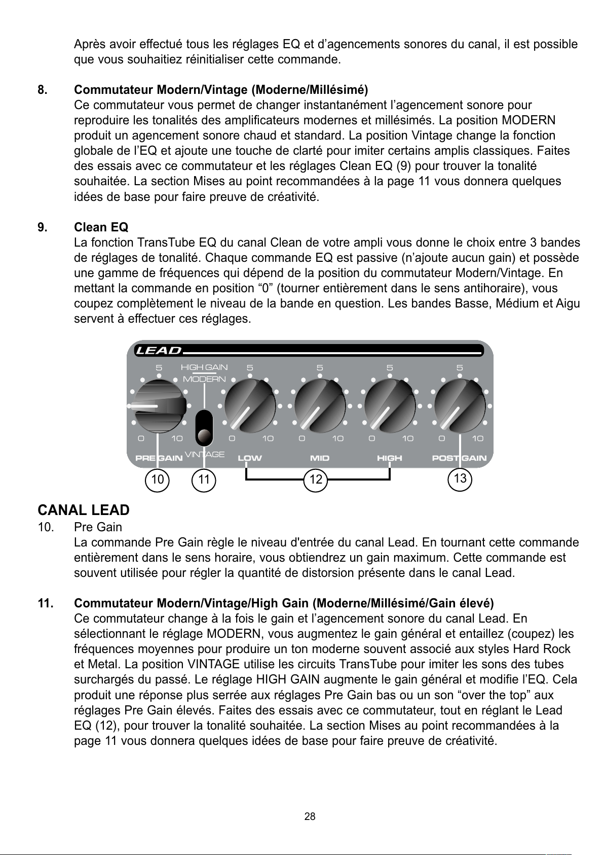
CANAL LEAD
10. Pre Gain
La commande Pre Gain règle le niveau d'entrée du canal Lead. En tournant cette commande
entièrement dans le sens horaire, vous obtiendrez un gain maximum. Cette commande est
souvent utilisée pour régler la quantité de distorsion présente dans le canal Lead.
11. Commutateur Modern/Vintage/High Gain (Moderne/Millésimé/Gain élevé)
Ce commutateur change à la fois le gain et l’agencement sonore du canal Lead. En
sélectionnant le réglage MODERN, vous augmentez le gain général et entaillez (coupez) les
fréquences moyennes pour produire un ton moderne souvent associé aux styles Hard Rock
et Metal. La position VINTAGE utilise les circuits TransTube pour imiter les sons des tubes
surchargés du passé. Le réglage HIGH GAIN augmente le gain général et modifie l’EQ. Cela
produit une réponse plus serrée aux réglages Pre Gain bas ou un son “over the top” aux
réglages Pre Gain élevés. Faites des essais avec ce commutateur, tout en réglant le Lead
EQ (12), pour trouver la tonalité souhaitée. La section Mises au point recommandées à la
page 11 vous donnera quelques idées de base pour faire preuve de créativité.
10 11
13
12
28
All manuals and user guides at all-guides.com
Page 29

12. Lead EQ
La fonction TransTube EQ du canal Lead de votre ampli vous donne le choix entre 3 bandes
de réglages de tonalité. Chaque commande EQ est passive (n’ajoute aucun gain) et possède
une gamme de fréquences qui dépend de la position du commutateur Modern/Vintage/High
Gain. En mettant la commande en position “0” (tourner entièrement dans le sens antihoraire),
vous coupez au maximum le niveau de la bande en question. Les bandes Basse, Médium et
Aigu servent à effectuer ces réglages.
13. Post Gain
Cette commande sert à régler le niveau général du canal Lead une fois que vous avez
trouvez votre tonalité. Pour commencer, il est préférable de tourner complètement la
commande dans le sens antihoraire (gain minimum), et de la tourner ensuite dans le sens
horaire jusqu'à atteindre le niveau souhaité. Après avoir effectué les réglages EQ et
d’agencement sonore du canal, il est possible que vous souhaitiez réinitialiser cette
commande.
SECTION MASTER
Les sections Master des amplis de la série TransTube varient selon le type d’appareil. Lisez-les
attentivement. Chaque description de fonction indique le(s) modèle(s) correspondant(s).
14. Reverb
La commande Reverb règle le niveau général de la réverbération. Cette commande se trouve
sur les trois modèles. Remarque: La reverb peut être supprimée à l'aide du commutateur à
distance (18) sur les modèles Envoy 110 et Studio Pro 112.
15. T-Dynamics
®
Cette commande règle le niveau de puissance de l’amplificateur de 10 à 100 pour cent. Pour
les niveaux inférieurs, la simulation de la compression de puissance sera beaucoup plus
prononcée. Cette commande se trouve sur le Studio Pro 112 et le Bandit 112.
16. Présence (rondeur du son)
Cette commande de tonalité active amplifie les fréquences extrêmement élevées d’un
maximum de 6 dB. Cette commande se trouve uniquement sur le Bandit 112.
17. Résonance
Ce commutateur règle la résonance à basse fréquence de l’enceinte acoustique en faisant
varier le facteur d’amortissement de l’amplificateur de deux façons: TIGHT (serré) et LOOSE
(détendu). En position TIGHT, l’amplificateur possède un facteur d’amortissement élevé, et
par conséquent la combinaison haut-parleur/coffre donne moins de résonance. La position
LOOSE permet aux caractéristiques de la combinaison ampli de puissance/coffre/haut-
parleur d’offrir plus de résonance à basse fréquence. Ainsi, la fréquence de résonance du
14
3
2
Envoy®110
14
3
15
2
Studio Pro®112
14
3
16 17 15
2
Bandit®112
29
All manuals and user guides at all-guides.com
Page 30

coffre sert à donner plus de basses aux fins des sons, simulant l’effet d’un plus grand coffre.
Cette commande se trouve uniquement sur le Bandit 112.
PANNEAU ARRIÈRE
Les fonctions du panneau arrière des amplis de la série TransTube varient suivant les appareils.
Veuillez les lire attentivement. Chaque description de fonction indique le(s) modèle(s)
correspondant(s).
18. Commutateur à distance
Cette prise accepte l’interrupteur à distance au pied de votre ampli. L’interrupteur au pied (en
option sur les modèles Envoy 110 et Studio Pro 112) est de type multifonction. Il sert à
sélectionner les canaux Clean ou Lead. En outre, l’interrupteur au pied est utilisé pour
activer/désactiver la reverb sur les modèles Envoy 110 et Studio Pro 112. Sur le Bandit,
l’interrupteur au pied (inclus) permet de sélectionner le canal et de supprimer la boucle à
effets. Le commutateur de sélection de canal (6) doit se trouver en position LEAD pour que le
commutateur à distance fonctionne.
19. Prise pour casques
Cette prise stéréo de 6,3 mm accepte une paire d’écouteurs standard. L’utilisation de cette
prise supprime la sortie vers le haut-parleur, ce qui est idéal pour des applications
silencieuses. Cette prise se trouve uniquement sur le modèle Envoy 110 .
REMARQUE: Les autres fonctions ne concernent que les modèles Studio Pro 112 et/ou
Bandit 112.
21
18
20
19
1
1
18
21 23 18
24
22
20
1
25
30
All manuals and user guides at all-guides.com
Page 31

20. Boucle à effets
Cette paire de prises mono de 6,3 mm produit un parcours SEND (Envoi) et RETURN
(Retour) des effets pour le signal du préampli. Brancher la prise SEND à l’entrée du matériel
de traitement de signal externe à faible niveau (effets). Renvoyez le signal de votre matériel
externe vers la prise RETURN. Ceci est appelé “boucle à effets” car le signal sort de votre
ampli (envoi) et revient en boucle (retour) vers ce même ampli. Sur le Bandit 112, la boucle à
effets peut être permutée vers l’intérieur et vers l’extérieur du parcours du signal à l’aide du
commutateur à distance (18).
21. Prise pour haut-parleur externe
Cette prise de 6,3 mm sert à brancher un coffre de haut-parleur externe comme le modèle
Peavey 412M. L’impédance minimale du haut-parleur externe est de 8 ohms. Cette prise sert
à débrancher le haut-parleur lorsqu'il est utilisé avec le Studio Pro 112.
REMARQUE: Les autres fonctions ne concernent que le modèle Bandit 112.
22. Preamp Out (Sortie de préampli)
Le Preamp Output sert à acheminer le signal du préampli vers une console de mixage, un
enregistreur à bandes, etc. A l’aide d’un câble d’instrument blindé muni de fiches mono de
6,3 mm, branchez le Preamp Output à l’entrée de votre matériel externe. Ce patch n’affecte
pas le fonctionnement normal de votre amplificateur.
23. Power Amp In (Alimentation ampli entrée)
Branchez les signaux de niveau de ligne du matériel externe à cette entrée. En insérant une
fiche dans cette prise mono de 6,3 mm, vous empêcherez la transmission du signal du
préampli TransTube vers l’amplificateur. Dans cette configuration, l’ampli de puissance
n’affecte que le signal introduit dans la prise Power Amp In.
24. Niveau d'effets
Ce commutateur permet de sélectionner le niveau de fonctionnement de la boucle à effets
(20). Lorsque vous mettez le commutateur en position “in”, le niveau est réglé pour 0 dBV
(1 V RMS). En plaçant le commutateur en position “out”, le niveau passe à -10 dBV
(0.3 V RMS). Veuillez vous reporter au manuel de l’utilisateur pour que les effets externes
déterminent la position correcte de ce commutateur.
25. Interrupteur de mise à la terre
Placez cet interrupteur de mise à la terre en position centrale (0) durant le fonctionnement
normal. Si vous entendez un ronflement, positionnez l’interrupteur de mise à la terre en
position positive (+) ou négative (-) pour minimiser le bruit. Vous pouvez être amené à
essayer les deux positions pour trouver la plus silencieuse.
25
31
All manuals and user guides at all-guides.com
all-guides.com
Page 32

REMARQUE: Si le problème de bruit persiste, consultez un revendeur Peavey agréé ou le centre
de réparation Peavey. L’INTERRUPTEUR DE MISE A LA TERRE NE FONCTIONNE PAS SUR LES
MODELES DE 220/240 VOLT.
ENVOY®110
SPECIFICATIONS
SECTION AMPLIFICATEUR DE PUISSANCE:
Puissance au point de saturation: (en général)
(
5% THD, 1 kHz, ligne CA 120V)
40W RMS en 6 Ohms
Réponse de fréquence:
+0, -2 dB 100 Hz to 20 kHz à 35W RMS
en 6 Ohms
Ronflement et bruit:
Plus de -86 dB en dessous de la puissance
nominale
Consommation d'énergie:
75W à 60 Hz, 120V CA, Domestique
75W à 50/60 Hz, 220-230/240V CA,
Exportation
SECTION PRÉAMPLI:
Les spécifications ci-dessous sont mesurées à 1 kHz
avec des commandes réglées comme suit:
Sélection de canal, Clean
Commutateur de mode Clean, Modern
Basse et Aigu à 10
Médium à 0
Lead Pre et Post Gain à 10
Commutateur de mode Lead, Vintage
Reverb à 0
Niveaux nominaux avec volume Clean à 5
Niveaux minimaux avec volume Clean à 10
Entrée de gain élevé du préampli:
Impédance: High Z, 250 K Ohms
Nominal Input Level (Niveau d’entrée
nominal): -13 dBV, 225mV RMS
Minimum Input Level (Niveau d’entrée
minimal): -22 dBV, 82mV RMS
Maximum Input Level (Niveau d’entrée
maximal): +0 dBV, 1V RMS
Entrée de gain bas du préampli:
Impédance: High Z, 44k Ohms
Nominal Input Level (Niveau d’entrée
nominal): -7dBV, 450mV RMS
Minimum Input Level (Niveau d’entrée
minimal): -16dBV, 164mV RMS
Maximum Input Level (Niveau d’entrée
maximal): +6dBV, 2V RMS
Headphone Output (Sortie casque):
Impédance de charge: 16 Ohms ou plus
Nominal Output Level (Niveau de sortie
nominal): -3 dBV, 0,7V RMS
Système de ronflement et de bruit au niveau
d'entrée nominal:
(
20 Hz à 20 kHz non pondéré)
Plus de 78 dB en dessous de la puissance
nominale
Correction:
Spéciale basse, médium et aigu passive de type EQ
(« équaliseur »).
Commutateur Modern/Vintage (Clean): Deux
agencements sonores EQ différents.
Commutateur Modern/Vintage/High Gain:
Trois agencements sonores EQ et
Gain différents
Fonctions de l’interrupteur à pied externe:
Sélection: Sélection canal Clean ou Lead.
Reverb: Dérivation de reverb
Dimensions (H x L x P):
16" H x 18,13" W x 9,5" D
40,1cm x 46,1cm x 24,1cm
Poids:
21,7 lbs. (9,84 kg)
32
All manuals and user guides at all-guides.com
Page 33

SECTION AMPLIFICATEUR DE PUISSANCE:
Puissance et charge nominales:
Les spécifications de puissance sont mesurées avec
T-Dynamics à 100%
65W RMS en 8 Ohms
Puissance au point de saturation:
(en général)
(5% THD, 1 kHz, ligne CA 120V)
65W RMS en 8 Ohms
Réponse de fréquence:
+3, -0 dB 100 Hz à 20 kHz à 45W RMS en
8 Ohms
Ronflement et bruit:
Plus de 88 dB en dessous de la puissance
nominale
Consommation d’énergie:
200W à 60 Hz, 120V CA, Domestique
200W à 50/60 Hz, 220-230/240V CA,
Exportation
SECTION PRÉAMPLI:
Les spécifications ci-dessous sont mesurées à 1 kHz
avec des commandes réglées comme suit:
Sélection de canal, Clean
Commutateur de mode Clean, Modern
Basse et aigu à 10
Médium à 0
Lead Pre et Post Gain à 10
Commutateur de mode Lead, Vintage
Reverb à 0
Niveaux nominaux avec volume Clean à 5
Niveaux minimaux avec volume Clean à 10
Entrée de gain élevé du préampli:
Impédance: High Z, 250 K Ohms
Nominal Input Level (Niveau d’entrée
nominal): -12 dBV, 250mV RMS
Minimum Input Level (Niveau d’entrée
minimal): -23 dBV, 71mV RMS
Maximum Input Level (Niveau d’entrée
maximal): +0 dBV, 1V RMS
Entrée de gain bas du préampli:
Impédance: High Z, 44 k Ohms
Nominal Input Level (Niveau d'entrée
nominal): -6 dBV, 500mV RMS
Minimum Input Level (Niveau d'entrée
minimal): -17dBV, 142mV RMS
Maximum Input Level (Niveau d'entrée
maximal): +6 dBV, 2V RMS
Effects Send (Envoi effets):
Impédance de charge: 1k Ohms ou plus
Nominal Output Level (Niveau de sortie
nominal):
Niveau d'effets -9dBV, 355 mV RMS
Effects Return (Retour effets):
Impédance: High Z, 22k Ohms
Designed Input Level (Niveau d'entrée
prévue):
Niveau d'effets -9dBV, 355 mV RMS
(Prise à commutation permettant un branchement
Effects Send à Effects Return, lorsqu’il n’est pas
utilisé).
Système de ronflement et de bruit au niveau
d’entrée nominal:
(20Hz à 20kHz non pondéré)
Plus de 74 dB en dessous de la puissance
nominale
Correction:
Spéciale basse, médium et aigu passive de
type EQ (« équaliseur »)
Commutateur Modern/Vintage (Clean): Deux
agencements sonores EQ différents
Commutateur Modern/Vintage/High Gain:
Trois agencements sonores EQ et
Gain différents
Fonctions de l‘interrupteur à pied externe:
Sélection: Sélection canal Clean ou Lead
Reverb: Dérivation de reverb
Dimensions (H x L x P):
18" x 21,5" x 10,5"
45,7cm x 54,6cm x 26,7cm
Poids:
34,1 lbs. (15,47kg)
STUDIO PRO 112
SPECIFICATIONS
33
All manuals and user guides at all-guides.com
Page 34

SECTION
AMPLIFICATEUR DE PUISSANCE:
Puissance et charge nominales:
Les spécifications de puissance sont mesurées avec
T-Dynamics à 100%
80W RMS en 8 Ohms
100W RMS en 4 Ohms
Puissance au point de saturation: (en général)
(5% THD, 1 kHz, ligne CA 120V)
80W RMS en 8 Ohms
100W RMS en 4 Ohms
Réponse de fréquence:
+0, -3 dB 100 Hz à 20 kHz à 45W RMS en
8 Ohms
Ronflement et bruit:
Plus de 88 dB en dessous de la puissance
nominale
Consommation d’énergie:
300W à 60 Hz, 120V CA, Domestique
300W à 50/60 Hz, 220-230/240V CA,
Exportation
Section Préampli:
Les spécifications ci-dessous sont mesurées à 1 kHz
avec des commandes réglées comme suit:
Sélection de canal, Clean
Commutateur de mode Clean, Modern
Basse et aigu à 10
Médium à 0
Lead Pre et Post Gain à 10
Commutateur de mode Lead, Vintage
Reverb à 0
Niveaux nominaux avec volume Clean à 5
Niveaux minimaux avec volume Clean à 10
Entrée de gain élevé du préampli:
Impédance: High Z, 250 K Ohms
Nominal Input Level (Niveau d’entrée
nominal): -14 dBV, 185mV RMS
Minimum Input Level (Niveau d’entrée
minimal): -23 dBV, 66mV RMS
Maximum Input Level (Niveau d’entrée
maximal): +0 dBV, 1V RMS
Entrée de gain bas du préampli:
Impédance: High Z, 44 k Ohms
Nominal Input Level (Niveau d'entrée
nominal): -8 dBV, 380mV RMS
Minimum Input Level (Niveau d'entrée
minimal): -17 dBV, 136 mV RMS
Maximum Input Level (Niveau d'entrée
maximal): +6 dBV, 2 V RMS
Effects Send (Envoi effets):
Impédance de charge: 1 k Ohms ou plus
Nominal Output Level (Niveau de sortie nominal):
Commutateur de niveau d’effets “out”:
-10 dBV, 0,32V RMS
Commutateur de niveau d’effets “in”: 0 dBV,
1V RMS
Effects Return (Retour effets):
Impédance: High Z, 22k Ohms
Designed Input Level (Niveau d’entrée prévue):
Commutateur de niveau d’effets “out”:
-10 dBV,
0.32V RMS
Commutateur de niveau d’effets “in”: 0dBV,
1V RMS
(Prise à commutation permet un branchement Effects
Send à Effects Return, lorsqu’il n’est pas utilisé).
Sortie de préampli:
Impédance de charge: 1 k Ohms ou plus
Nominal Output Level (Niveau de sortie
nominal): 0 dBV, 1V RMS
Entrée d’ampli de puissance:
Impédance: High Z, 22k Ohms
Designed Input Level (Niveau d'entrée
prévue): 0 dBV, 1V RMS
(Prise à commutation permettant un branchement
sortie de préampli à entrée d’ampli de puissance,
lorsqu’il n’est pas utilisé).
Système de ronflement et de bruit au niveau
d'entrée nominal:
(20 Hz à 20 kHz non pondéré)
Plus de 78 dB en dessous de la puissance
nominale
BANDIT®112
SPECIFICATIONS
34
All manuals and user guides at all-guides.com
Page 35

Correction:
Spéciale basse, médium et aigu passive de
type EQ (« équaliseur »)
Commutateur Modern/Vintage (Clean): Deux
agencements sonores EQ différents
Commutateur Modern/Vintage/High Gain:
Trois agencements sonores EQ et Gain différents
Présence: +6 dB à 5 kHz
Résonance de poussée: +6 dB à fréquence
de résonance du coffre
Fonctions de l'interrupteur à pied externe:
Sélection: Sélection canal Clean ou Lead
Effets: Dérivation de boucle à effets
Dimensions (H x L x P):
19,75" x 23,63" x 11,5"
50,16cm x 60,02cm x 29,2cm
Poids:
43,9 lbs. (19,91 kg)
35
All manuals and user guides at all-guides.com
Page 36

Envoy®110, Studio®Pro 112 und Bandit®112
Transtube®Series-Instrumentenverstärker
Herzlichen Glückwunsch zum Kauf eines Peavey Transtube®-Series-Instrumentenverstärker. Ob Sie
nun ein Anfänger sind oder semiprofessionell arbeiten, Sie werden keinen praktischeren Verstärker
mit so vielen Funktionen finden. Der patentierte Transtube von Peavey ist Marktführer der zweiten
Generation von Röhren emulierenden Verstärkern. Es gibt keinen anderen volltransistorierten
Verstärker auf dem Markt, der ähnlich genau die Charakteristiken eines Röhrenverstärkers
nachbildet.
In dieser Gebrauchsanleitung werden drei Transtube-Serienmodelle beschrieben, deren Funktionen
leicht variieren. Die Modelle heißen: Envoy
®
110, Studio Pro®112 und Bandit®112. Auf die
Unterschiede der drei Modelle wird hingewiesen. Die nachfolgende Auflistung beschreibt die
wesentlichen Funktionen und Unterschiede der Verstärker untereinander. Bitte lesen Sie diese
Gebrauchsanleitung ganz durch, damit eine optimale und sichere Bedienung Ihres neuen
Transtube-Verstärkers gewährleistet ist.
ALLGEMEINE FUNKTIONEN
• High und Low Gain-Eingänge, für eine Vielfalt von Instrumenten
• Zwei unterschiedliche Transtube-Kanäle. Jeder Kanal hat:
• Separate Volume/Gain-Regler
• Low-, Mid- und High-EQ
• EQ/Gain-Voicing-Schalter
• Kanalwahl-Schalter auf vorderem Bedienfeld
• Feder-Hall mit Reverb-Level-Regler
• Anschlussmöglichkeit eines Fußschalters
ENVOY 110-FUNKTIONEN
• 10"-Blue-Marvel
®
-Lautsprecher
• 40 Watt-Verstärker
• Preamp-Ausgang
• Kopfhörerbuchse
• Reverb- und Kanalwahl per Fußschalter
STUDIO PRO 112-FUNKTIONEN
• 12"-Blue-Marvel-Lautsprecher
• 65 Watt-Verstärker
• Effekte, Send und Return
• T. Dynamics
®
-Regler
• Externe Lautsprecherbuchse
• Reverb- und Kanalwahl per Fußschalter
BANDIT 112-FUNKTIONEN
• 12"-Sheffield
®
1230-Lautsprecher
• 100 Watt Verstärker (80 Watt im eingebauten Lautsprecher)
• Einschleifweg für Effekte und Kanalwahl per Fußschalter
• Effects-Level-Schalter
DEUTSCH
36
All manuals and user guides at all-guides.com
all-guides.com
Page 37

• Preamp-Ausgang
• Verstärker-Eingang
• Externe Lautsprecherbuchse
• T-Dynamics
®
-Regler
• Presence-Regler
• Resonance-Schalter
NETZANSCHLUSS
Bevor Sie Ihren Transtube-Series-Verstärker an das Netz anschließen, prüfen Sie die
Spannungsleistung Ihrer Stromquelle. Die geeignete Spannungsleistung für Ihren Verstärker ist auf
der oberen linken Ecke Ihres rückseitigen Bedienfeldes abzulesen.
1. Netzkabel (im Gehäuse)
In der hinteren Gehäuseöffnung, bei dem Lautsprecher, finden Sie das Netzkabel. Dieses
Kabel überträgt die Netzspannung an das Gerät. Verbinden Sie dieses Kabel mit einem
richtig geerdeten Wechselstromanschluss. Ihr Verstärker kann Schaden erleiden, wenn eine
unkorrekte Spannungsleistung gewählt wird. (Sehen Sie dazu den Hinweis auf die
Spannungsleistung an Ihrem Gerät.) Enfernen Sie nie den Erdungskontakt von Ihrem
Netzstecker.
2. Netzschalter (sehen Sie dazu im Abschnitt “Master” die Darstellung 7.)
Drücken Sie diesen Schalter auf “ON”, um das Gerät einzuschalten. Das Power-LED (3)
leuchtet auf und weist darauf hin, dass das Gerät eingeschalten ist. Wenn Sie den unteren
Teil des Schalters drücken, schaltet der Verstärker sich wieder aus.
3. Power-LED (sehen Sie dazu im Abschnitt “Master” die Darstellung 7.)
Die aufleuchtende LED-Anzeige zeigt an, dass der Verstärker angeschalten ist.
TRANSTUBE-PREAMP
Der Transtube-Preamp Ihres Verstärkers besteht aus drei klar ausgewiesenen Bereichen: Inputs
(Eingänge), Clean (Kanal) und Lead (Kanal). Sehen wir uns jedes dieser Felder genau an.
Eingänge
Die Empfindlichkeit der Eingänge Ihres Transtube-Series-Verstärkers sind so konstruiert, dass sie
sich genau so verhalten wie die eines herkömmlichen Röhrenverstärkers. Verwenden Sie immer
abgeschirmte Instrumentenkabel hoher Qualität, wenn Sie Ihr Instrument mit dem Input des
Verstärkers verbinden.
4. High Gain-Eingang
Das ist der Standard-Eingang, den Sie für viele Instrumente benutzen können. Viele
elektrische Gitarren funktionieren optimal, wenn Sie in diesen 6,3 mm Mono-Eingang
einstecken. Der High Gain-Eingang ist 6 dB lauter als der Low Gain-Eingang (5).
5
4
37
All manuals and user guides at all-guides.com
Page 38

5. Low Gain-Eingang
Dieser 6,3 mm Mono-Eingang ist für Instrumente mit sehr hohen Output-Levels gedacht,
welche den High Gain-Eingang (4) übersteuern (verzerren) können. Wenn beide, der Low
Gain- und der High Gain-Eingang gleichzeitig benutzt werden, sind ihre Levels beide Low
Gain. Die Kanäle Ihres Tube Series-Verstärkers bieten Ihnen einen 2-Kanal-Betrieb an.
Beide, der Clean- und der Lead-Kanal, liefern Ihnen eine flexible Plattform für Ihren eigenen,
bevorzugten Ton. Der Fußschalter (optional für den Envoy 110 und den Studio Pro 112)
ermöglicht das Umschalten zwischen den beiden Kanälen per Fuß und wird detailliert auf der
Seite 8 dieses Handbuches beschrieben.
6. Kanalwahl-Schalter
Der Kanalwahl-Schalter gibt an, welcher Kanal des Transtube-Preamps, LEAD oder CLEAN,
aktiviert ist. Dieser Schalter muss in der “LEAD”-Position sein, damit der Fußschalter Ihres
Verstärkers ordungsgemäß funktioniert.
Clean-Kanal
7. Volume
Dieser Regler bestimmt das Volume-Level Ihres Clean-Kanals. Es ist ratsam, die
Einstellungen mit dem Regler gegen den Uhrzeigersinn (Minimum Gain), ganz zurückgedreht,
zu beginnen und im Uhrzeigersinn den gewünschten Pegel einzustellen. Nachdem alle EQ-
und Voicing-Einstellungen für den Kanal vorgenommen wurden, stellen Sie den Regler auf
die gewünschte Position zurück.
6
7 8 9
38
All manuals and user guides at all-guides.com
Page 39

8. Modern/Vintage-Schalter
Mit diesem Schalter können Sie sehr schnell zwischen Voicings eines modernen und eines
Vintage-Verstärkers wählen. Die Schalterposition MODERN beschreibt ein warmes Standard-
Voicing. Die Funktion des EQs wird grundlegend mit der Position VINTAGE verändert und
fügt dem Klang einen Hauch Helligkeit hinzu. Damit bildet Ihr Verstärker die
Klangvorstellungen klassicher Verstärker nach (Emulation). Experimentieren Sie gemeinsam
mit verschiedenen EQ-Settings (9) und dem Modern/Vintage-Schalter, um Ihren gewünschten
Ton zu bekommen. Für kreative Hinweise sehen Sie sich die empfohlenen Einstellungen auf
Seite 11 an.
9. Clean-EQ
Der Transtube-EQ in Verbindung mit dem Clean-Kanal Ihres Verstärkers ermöglicht Ihnen
eine 3-Band-Klangregelung. Jeder EQ-Regler ist passiv (fügt kein Gain hinzu) und hat einen
Frequenzbereich, der von der Position des Modern/Vintage-Schalters abhängt. In der “0”
Position (gegen den Uhrzeigersinn bis zum Anschlag) reduzieren Sie maximal die Frequenz
des jeweiligen Bandes. Low-, Mid- und High-Bänder sind zur Anpassung vorhanden.
LEAD-KANAL
10. Pre Gain
Der Pre Gain-Regler bestimmt den Input-Level für den Lead-Kanal. Ein Maximum an Gain
erzielen Sie, wenn Sie den Regler bis zum Anschlag im Uhrzeigersinn aufdrehen. Dieser
Regler wird häufig benutzt, um die Intensität der Verzerrung im Lead-Kanal einzustellen.
11. Modern/Vintage/High-Gain-Schalter
Dieser Schalter ändert Gain und Voicing des Lead-Kanals. Die Position MODERN erhöht die
Gain-Leistung insgesamt und senkt die mittleren Frequenzen ab, sodass ein moderner Sound
entsteht, den man mit Hard Rock und Metal assoziieren kann. Einen übersteuerten,
klassischen Röhren-Sound emulieren Sie mit der VINTAGE-Position Ihres Schalters. Mit der
HIGH GAIN-Einstellung heben Sie die gesamte Intensität der Verzerrung an und verändern
ihren EQ. Dies erzeugt ein kompakteres Ansprechverhalten bei niedrigeren Pre-Gain-Settings
oder einen spitzeren Sound bei höheren Pre-Gain-Settings. Sie erhalten Ihren gewünschten
Ton, wenn Sie mit diesen Schaltereinstellungen experimentieren und den Lead-EQ (12)
nachregeln. Für kreative Hinweise sehen Sie sich die empfohlenen Einstellungen auf Seite
11 an.
12. Lead EQ
Der Transtube-EQ in Verbindung mit dem Lead-Kanal Ihres Verstärkers bietet Ihnen eine
3-Band-Klangregelung. Jeder EQ-Regler ist passiv (fügt kein Gain hinzu) und hat einen
Frequenzbereich, der von der Position des Modern/Vintage/High-Gain-Schalters abhängt. In
10 11
13
12
39
All manuals and user guides at all-guides.com
Page 40

der “0” Position (gegen den Uhrzeigersinn bis zum Anschlag) reduzieren Sie maximal die
Frequenz des jeweiligen Bandes. Low-, Mid- und High-Bänder sind zur Klangregelung
vorhanden.
13. Post Gain
Wenn Sie jetzt Ihre eigene Klangvorstellung eingestellt haben, benützen Sie den Post Gain-
Regler für die Settings des Gesamt-Levels des Lead-Kanals. Am Besten beginnen Sie ihre
Einstellungen mit einem im Uhrzeigersinn ganz zurückgedrehten Regler (Minimum Gain) und
justieren im Uhrzeigersinn solange, bis Ihr gewünschtes Level erreicht ist. Nachdem alle EQ-
und Voicing-Einstellungen für den Kanal ausgeführt sind, können Sie den Regler
zurückstellen.
MASTER-SEKTION
Die Master-Sektionen des Transtube-Series-Verstärkers variieren von Modell zu Modell. Bitte lesen
Sie dazu sorgfältig die einzelnen Funktionen nach. Jedes Modell hat seine eigene
Funktionsbeschreibung.
14. Reverb
Der Reverb-Regler stimmt das gesamte Reverb-Level ab. Sie finden diesen Regler auf allen
Modellen. Beachten Sie: Der Reverb kann mit dem Fußschalter (18) bei den Modellen Envoy
110 und Studio Pro 112 ein- und ausgeschaltet werden.
15. T-Dynamics
®
Dieser Regler justiert den Power-Level des Verstärkers von 10% bis zu 100%. Bei
niedrigeren Settings wird die Stimulation der Power-Compression wesentlich stärker
angesprochen. Sie finden diesen Regler bei den Modellen Studio Pro 112 und Bandit 112.
16. Presence
Dieser aktive Tone-Regler hebt die extrem hohen Frequenzen um 6 dB an. Sie finden diesen
Regler nur im Bandit 112.
17. Resonance
Der Resonance-Schalter beschreibt den Dämpfungsfaktor in Ihrem Verstärker. Dadurch
können Sie die Resonanz der unteren Frequenzen an Ihrem Lautsprecher steueren. Zwei
Settings sind möglich: TIGHT und LOOSE. In der TIGHT-Position dämpft der Verstärker
intensiver den Lautsprecher bzw. die extern angeschlossene Box. Geringere Resonanzen der
Lautsprecher sind die Folge. Schalten Sie auf LOOSE, kehrt sich der Effekt um, und die
Resonanzen der niedrigeren Frequenzen erhöhen sich. Dieser Effekt ist sehr nützlich, wenn
Sie eine externe größere Box benutzen, um mehr Low-End zu produzieren. Sie finden diesen
Regler nur bei dem Modell Bandit 112.
14
3
2
Envoy®110
14
3
15
2
Studio Pro®112
14
3
16 17 15
2
Bandit®112
40
All manuals and user guides at all-guides.com
Page 41

RÜCKSEITIGES BEDIENFELD
Die Funktionen auf dem rückseitigen Bedienfeld der Transtube-Series-Verstärker variieren von
Modell zu Modell. Bitte lesen Sie dazu sorgfältig die einzelnen Funktionen nach. Jedes Modell hat
seine eigene Funktionsbeschreibung.
18. Fußschalterbuchse
Diese Buchse ist der Eingang für den passenden Fußschalter Ihres Verstärkers. Der
Fußschalter (optional für Envoy 110 und Studio Pro 112) ist ein multifunktionales Gerät. Sie
wählen damit die Clean- und Lead-Kanäle an. Zusätzlich aktivieren/deaktivieren Sie den Hall
bei den Modellen Envoy 110 und Studio Pro 112. Der Fußschalter für den Bandit (im
Lieferumfang) schaltet die Kanäle um und aktiviert/deaktiviert den Einschleifweg für die
Effekte (20). Der Kanalwahl-Schalter (6) muss in der LEAD-Position sein, damit der
Fußschalter funktioniert.
19. Kopfhörereingang
Sie können in diese 6,3 mm-Stereo-Buchse einen handelsüblichen Kopfhörer anschließen.
Wenn Sie den Kopfhörer eingesteckt haben, wird automatisch der Lautsprecher deaktiviert.
Eine ideale Funktion, die störungsfreie Übungsstunden garantiert. Sie finden diese Buchse
nur bei dem Modell Envoy 110.
BEACHTEN SIE: Die verbleibenden Funktionen treffen nur für die Modelle Studio Pro 112
und/oder Bandit 112 zu.
20. Einschleifweg für Effekte
Diese zwei 6,3 mm-Mono-Buchsen liefern den SEND und RETURN-Einschleifweg für das
Preamp-Signal. Verbinden Sie die SEND-Buchse Ihres Verstärkers mit der Eingangsbuchse
21
18
20
19
1
1
18
21 23 18
24
22
20
1
25
41
All manuals and user guides at all-guides.com
all-guides.com
Page 42

des externen, Low-Level-Effektgerätes. Legen Sie das Return-Signal von Ihrem externen
Gerät zu der RETURN-Buchse Ihres Verstärkers. Diese Verbindung nennt sich Einschleifweg
für Effekte, da ein Signal von Ihrem Verstärker ausgeht (Send) und wieder zurück (Return)
eingeschleift wird. Mit dem Modell Bandit 112 können Sie die Effekt-Einschleifung mit dem
Fußschalter (18) aktivieren/deaktivieren.
21. Externe Lautsprecherbuchse
Die 6,3 mm-Buchse ermöglicht den Anschluss einer externen Lautsprecher-Box, wie z. B. die
Peavey 412M. Die minimale Impedanz des Lautsprechers sollte 8 Ohm betragen. Ist eine
externe Box an dieser Buchse angeschlossen, wird bei dem Studio 112 der interne
Lautsprecher deaktiviert.
BEACHTEN SIE: Die verbleibenden Funktionen treffen nur für das Modell Bandit 112 zu.
22. Preamp-Out
Der Preamp-Ausgang kann dazu benutzt werden, um das Preamp-Signal in einen Mixer, eine
Bandmaschine, etc. zu leiten. Benutzen Sie dazu ein abgeschirmtes Instrumentenkabel mit
einem 6,3 mm-Mono-Stecker. Verbinden Sie den Preamp-Ausgang mit dem Eingang Ihres
externen Gerätes. Der normale Betrieb Ihres Verstärkers wird dadurch nicht gestört.
23. Power-Amp-In
Power-Amp-In verbindet Line-Level-Signale eines externen Gerätes (Verstärker) mit diesem
Eingang. Ein Stecker in dieser 6,3 mm-Monobuchse verhindert, dass ein Signal von dem
Transtube-Preamp an den internen Verstärker weitergeleitet werden kann. Der Power-Amp
selbst verstärkt in dieser Konfiguration das Signal nur an der Power-Amp-Buchse.
24. Effects-Level
Der Effects-Level-Schalter steuert den Pegel für den Einschleifweg der Effekte (20). Auf der
“in”-Position liegt der Pegel bei 0 dBV (1 V RMS). Stellen Sie den Schalter auf die “out”-
Position und Sie erhalten einen Pegel bei -10 dBV (0.3 V RMS). Für eine korrekte Schalter-
Einstellung folgen Sie den Hinweisen der Gebrauchsanleitung Ihrer externen Effekte.
25. Ground-Schalter
Für den Normalbetrieb stellen Sie diesen Schalter in die Mittelpostition (0). Falls Sie ein
Brummen hören, setzen Sie den Ground-Schalter (Erdungsschalter) entweder in die Positiv-
(+) oder in die Negativ-Position (-). So verringern Sie Nebengeräusche. Testen Sie beide
Positionen und wählen jene, die das Brummen am Besten unterdrückt.
25
42
All manuals and user guides at all-guides.com
Page 43

BEACHTEN SIE: Lassen sich die Geräusche nicht beseitigen, sprechen Sie mit Ihrem Peavey-
Händler. DER GROUND-SCHALTER FUNKTIONIERT NICHT BEI 220/240 VOLT-BETRIEB.
ENVOY®110
SPEZIFIKATIONEN
VERSTÄRKER-TEIL:
Power @ Clipping: (Standard)
(5% THD, 1 kHz, 120V AC-Line)
40W RMS in 6 Ohm
Frequency Response:
+0, -2 dB 100 Hz bis 20 kHz @ 35W RMS in
6 Ohm
Hum und Noise:
Mehr als -86 dB unterhalb der Nennleistung
Stromverbrauch:
75W @ 60 Hz, 120V AC, für die USA
75W @ 50/60 Hz, 220-230/240V AC, Export
Preamp-Teil:
Die folgenden Spezifikationen wurden @ 1 kHz
gemessen, mit folgenden Voreinstellungen:
Kanal-Auswahl, Clean
Clean Mode-Schalter, Modern
Low und High @ 10
Mid @ 0
Lead Pre und Post Gain @ 10
Lead Mode-Schalter, Vintage
Reverb @ 0
Nominaler Level mit Clean Volume @ 5
Minimum-Level mit Clean Volume @ 10
Preamp High Gain-Eingang:
Impedanz: High Z, 250 K Ohm
Nominaler Input-Level: -13 dBV, 225mV RMS
Minimum-Input-Level: -22 dBV, 82mV RMS
Maximum-Input-Level: +0 dBV, 1V RMS
Preamp Low Gain-Eingang:
Impedanz: High Z, 44k Ohms
Nominaler Input-Level: -7dBV, 450mV RMS
Minimum-Input-Level: -16dBV, 164mV RMS
Maximum-Input-Level: +6dBV, 2V RMS
Kopfhörer-Ausgang:
Load-Impedanz: 16 Ohm oder mehr
Nominaler Output-Level: -3 dBV, 0,7V RMS
System Hum und Noise @ Nominalem Input-
Level:
(20 Hz bis 20 kHz unbewertet)
Mehr als 78 dB unterhalb der Nennleistung
Equalization:
Special Low, Mid und High passiv.
Modern/Vintage-Schalter (Clean):
Zwei getrennte EQ-Voicings.
Vintage/Modern/High-Gain-Schalter (Lead):
Drei verschiedene EQ- und Gain-Voicings
Externe Fußschalter-Funktionen:
Select: Clean- oder Lead-Kanalauswahl.
Reverb: Reverb Bypass
Maße (H x B x T):
16" H x 18,13" B x 9,5" T
40,1cm x 46,1cm x 24,1cm
Gewicht:
21,7 lbs, (9,84 kg)
43
All manuals and user guides at all-guides.com
Page 44

VERSTÄRKER-TEIL:
Nennleistung und Belastung:
Power-Spezifikationen, gemessen mit T-Dynamics @
100%
65W RMS in 8 Ohm
Power @ Clipping: (Standard)
(5% THD, 1 kHz, 120V AC-Line)
65W RMS in 8 Ohm
Frequency Response:
+3, -0 dB 100 Hz bis 20 kHz @ 45W RMS in
8 Ohm
Hum und Noise:
Mehr als 88 dB unterhalb der Nennleistung
Stromverbrauch:
200W @ 60 Hz, 120V AC, in den USA
200W @ 50/60 Hz, 220-230/240V AC, Export
Preamp-Teil:
Die folgenden Spezifikationen wurden @ 1 kHz
gemessen, mit folgenden Voreinstellungen:
Kanal-Auswahl, Clean
Clean Mode-Schalter, Modern
Low und High @ 10
Mid @ 0
Lead Pre und Post Gain @ 10
Lead Mode-Schalter, Vintage
Reverb @ 0
Nominaler Level mit einem Clean Volume @ 5
Minimum-Level mit einem Clean Volume @ 10
Preamp High Gain-Input:
Impedanz: High Z, 250 K Ohm
Nominaler Input-Level: -12 dBV, 250mV RMS
Minimum-Input-Level: -23 dBV, 71mV RMS
Maximum-Input-Level: +0 dBV, 1V RMS
Preamp Low Gain-Input:
Impedanz: High Z, 44 k Ohm
Nominaler Input-Level: -6 dBV, 500mV RMS
Minimum-Input-Level: -17dBV, 142mV RMS
Maximum-Input-Level: +6 dBV, 2V RMS
Effects Send:
Load-Impedanz: 1k Ohm oder mehr
Nominaler Output-Level:
Effects-Level -9dBV, 355 mV RMS
Effects Return:
Impedanz: High Z, 22k Ohm
Designed Input-Level:
Effects Level -9dBV, 355 mV RMS
(Buchse mit Schalter stellt eine Verbindung zwischen
Effects-Send zu Effects-Return her, wenn unbenutzt.)
System Hum und Noise @ Nominalem
Input-Level:
(20 Hz bis 20 kHz unbewertet)
Mehr als 74 dB unterhalb der Nennleistung
Equalization:
Special Low, Mid, und High passiv
Modern/Vintage-Schalter (Clean): Zwei
getrennte EQ-Voicings
Vintage/Modern/High-Gain-Schalter (Lead):
Drei verschiedene EQ- und Gain-
Voicings
Externe Fußschalter-Funktionen:
Select: Clean- oder Lead-Kanalauswahl.
Reverb: Reverb Bypass
Maße (H x B x T):
18" x 21,5" x 10,5"
45,7cm x 54,6cm x 26,7cm
Gewicht:
34,1 lbs. (15,47kg)
STUDIO®PRO 112
SPEZIFIKATIONEN
44
All manuals and user guides at all-guides.com
Page 45

VERSTÄRKER-TEIL:
Nennleistung und Belastung:
Power-Spezifikationen, gemessen mit T-Dynamics @
100%
80W RMS in 8 Ohm
100W RMS in 4 Ohm
Power @ Clipping: (Standard)
(5% THD, 1 kHz, 120V AC-Line)
80W RMS in 8 Ohm
100W RMS in 4 Ohm
Frequency Response:
+0, -3 dB 100 Hz bis 20 kHz @ 65W RMS
in 8 Ohm
Hum und Noise:
Mehr als -88 dB unterhalb der Nennleistung
Stromverbrauch:
300W @ 60 Hz, 120V AC, für die USA
300W @ 50/60 Hz, 220-230/240V AC, Export
Preamp-Teil:
Die folgenden Spzifikationen wurden @ 1 kHz
gemessen, mit folgenden Voreinstellungen:
Kanal-Auswahl, Clean
Clean Mode-Schalter, Modern
Low und High @ 10
Mid @ 0
Lead Pre und Post Gain @ 10
Lead Mode-Schalter, Vintage
Reverb @ 0
Nominale Level mit Clean Volume @ 5
Minimum-Level mit Clean Volume @ 10
Preamp High Gain-Eingang:
Impedanz: High Z, 250 K Ohm
Nominaler Input-Level: -14 dBV, 185mV RMS
Minimum-Input-Level: -23 dBV, 66mV RMS
Maximum-Input-Level: +0 dBV, 1V RMS
Preamp Low Gain-Eingang:
Impedanz: High Z, 44 k Ohm
Nominaler Input-Level: -8 dBV, 380 mV RMS
Minimum-Input-Level: -17 dBV, 136 mV RMS
Maximum-Input-Level: +6 dBV, 2 V RMS
Effects Send:
Load-Impedanz: 1 k Ohm oder mehr
Nominaler Output-Level:
Effects Level-Schalter “out”: -10 dBV,
0,32V RMS
Effects Level-Schalter “in”: 0 dBV, 1V RMS
Effects Return:
Impedanz: High Z, 22k Ohm
Designed Input-Level:
Effects Level-Schalter “out”: -10 dBV,
0,32V RMS
Effects Level-Schalter “in”: 0dBV, 1V RMS
(Buchse mit Schalter stellt eine Verbindung zwischen
Effects-Send zu Effects-Return her, wenn unbenutzt.)
Preamp Output:
Load-Impedanz: 1 k Ohm oder mehr
Nominaler Output-Level: 0 dBV, 1V RMS
Power Amp Input:
Impedanz: High Z, 22k Ohm
Designed Input-Level: 0 dBV, 1V RMS
(Buchse mit Schalter stellt eine Verbindung zwischen
Effects-Send zu Effects-Return her, wenn unbenutzt.)
System Hum und Noise @ Nominalem Input-
Level:
(20 Hz bis 20 kHz unbewertet)
Mehr als 78 dB unterhalb der Nennleistung
Equalization:
Special Low, Mid und High passiv
Modern/Vintage-Schalter (Clean): Zwei
getrennte EQ-Voicings
Vintage/Modern/High-Gain-Schalter (Lead):
Drei verschiedene EQ- und Gain-Voicings
Presence: +6 dB @ 5 kHz
Push Resonance: +6 dB @
Resonanzfrequenz, Cabinet
Externe Fußschalter-Funktionen:
Select: Clean oder Lead-Kanalauswahl
Effects: Effects-Loop Bypass
Maße (H x B x T):
19,75" x 23,63" x 11,5"
50,16cm x 60,02cm x 29,2cm
Gewicht:
43,9lbs. (19,91kg)
BANDIT®112
SPEZIFIKATIONEN
45
All manuals and user guides at all-guides.com
Page 46
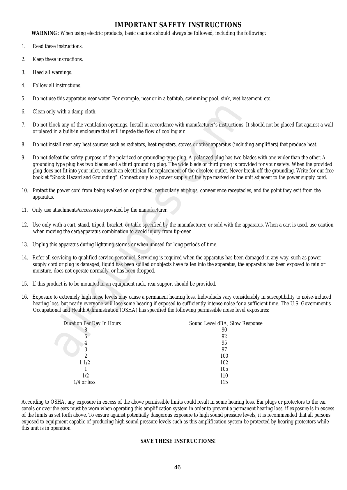
IMPORTANT SAFETY INSTRUCTIONS
WARNING: When using electric products, basic cautions should always be followed, including the following:
1. Read these instructions.
2. Keep these instructions.
3. Heed all warnings.
4. Follow all instructions.
5. Do not use this apparatus near water. For example, near or in a bathtub, swimming pool, sink, wet basement, etc.
6. Clean only with a damp cloth.
7. Do not block any of the ventilation openings. Install in accordance with manufacturer’s instructions. It should not be placed flat against a wall
or placed in a built-in enclosure that will impede the flow of cooling air.
8. Do not install near any heat sources such as radiators, heat registers, stoves or other apparatus (including amplifiers) that produce heat.
9. Do not defeat the safety purpose of the polarized or grounding-type plug. A polarized plug has two blades with one wider than the other. A
grounding type plug has two blades and a third grounding plug. The wide blade or third prong is provided for your safety. When the provided
plug does not fit into your inlet, consult an electrician for replacement of the obsolete outlet. Never break off the grounding. Write for our free
booklet “Shock Hazard and Grounding”. Connect only to a power supply of the type marked on the unit adjacent to the power supply cord.
10. Protect the power cord from being walked on or pinched, particularly at plugs, convenience receptacles, and the point they exit from the
apparatus.
11. Only use attachments/accessories provided by the manufacturer.
12. Use only with a cart, stand, tripod, bracket, or table specified by the manufacturer, or sold with the apparatus. When a cart is used, use caution
when moving the cart/apparatus combination to avoid injury from tip-over.
13. Unplug this apparatus during lightning storms or when unused for long periods of time.
14. Refer all servicing to qualified service personnel. Servicing is required when the apparatus has been damaged in any way, such as power-
supply cord or plug is damaged, liquid has been spilled or objects have fallen into the apparatus, the apparatus has been exposed to rain or
moisture, does not operate normally, or has been dropped.
15. If this product is to be mounted in an equipment rack, rear support should be provided.
16. Exposure to extremely high noise levels may cause a permanent hearing loss. Individuals vary considerably in susceptibility to noise-induced
hearing loss, but nearly everyone will lose some hearing if exposed to sufficiently intense noise for a sufficient time. The U.S. Government’s
Occupational and Health Administration (OSHA) has specified the following permissible noise level exposures:
Duration Per Day In Hours Sound Level dBA, Slow Response
890
692
495
397
2 100
1 1/2 102
1 105
1/2 110
1/4 or less 115
According to OSHA, any exposure in excess of the above permissible limits could result in some hearing loss. Ear plugs or protectors to the ear
canals or over the ears must be worn when operating this amplification system in order to prevent a permanent hearing loss, if exposure is in excess
of the limits as set forth above. To ensure against potentially dangerous exposure to high sound pressure levels, it is recommended that all persons
exposed to equipment capable of producing high sound pressure levels such as this amplification system be protected by hearing protectors while
this unit is in operation.
SAVE THESE INSTRUCTIONS!
46
All manuals and user guides at all-guides.com
all-guides.com
Page 47
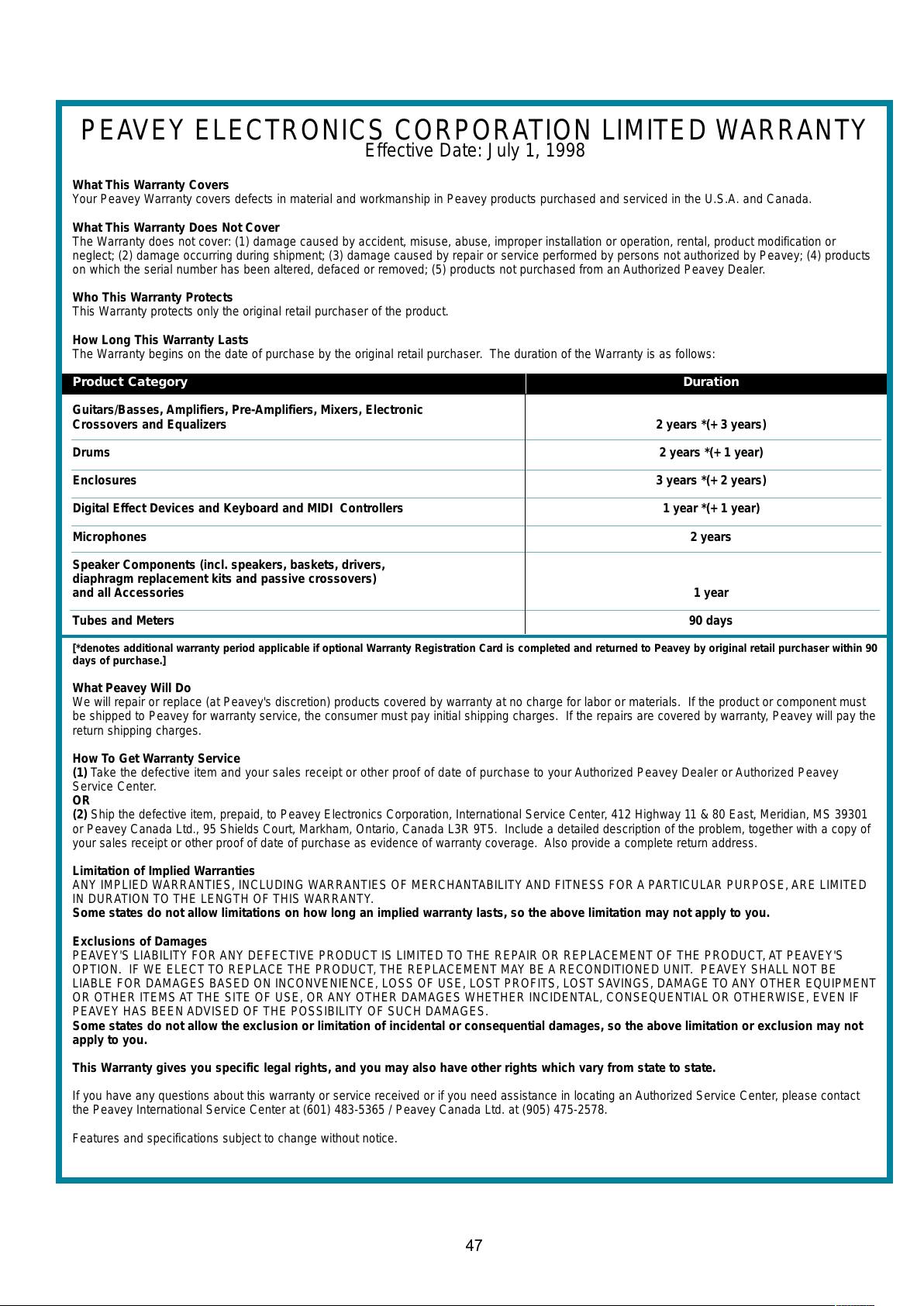
PEAVEY ELECTRONICS CORPORATION LIMITED WARRANTY
Effective Date: July 1, 1998
What This Warranty Covers
Your Peavey Warranty covers defects in material and workmanship in Peavey products purchased and serviced in the U.S.A. and Canada.
What This Warranty Does Not Cover
The Warranty does not cover: (1) damage caused by accident, misuse, abuse, improper installation or operation, rental, product modification or
neglect; (2) damage occurring during shipment; (3) damage caused by repair or service performed by persons not authorized by Peavey; (4) products
on which the serial number has been altered, defaced or removed; (5) products not purchased from an Authorized Peavey Dealer.
Who This Warranty Protects
This Warranty protects only the original retail purchaser of the product.
How Long This Warranty Lasts
The Warranty begins on the date of purchase by the original retail purchaser. The duration of the Warranty is as follows:
Product Category Duration
Guitars/Basses, Amplifiers, Pre-Amplifiers, Mixers, Electronic
Crossovers and Equalizers 2 years *(+ 3 years)
Drums 2 years *(+ 1 year)
Enclosures 3 years *(+ 2 years)
Digital Effect Devices and Keyboard and MIDI Controllers 1 year *(+ 1 year)
Microphones 2 years
Speaker Components (incl. speakers, baskets, drivers,
diaphragm replacement kits and passive crossovers)
and all Accessories 1 year
Tubes and Meters 90 days
[*denotes additional warranty period applicable if optional Warranty Registration Card is completed and returned to Peavey by original retail purchaser within 90
days of purchase.]
What Peavey Will Do
We will repair or replace (at Peavey's discretion) products covered by warranty at no charge for labor or materials. If the product or component must
be shipped to Peavey for warranty service, the consumer must pay initial shipping charges. If the repairs are covered by warranty, Peavey will pay the
return shipping charges.
How To Get Warranty Service
(1) Take the defective item and your sales receipt or other proof of date of purchase to your Authorized Peavey Dealer or Authorized Peavey
Service Center.
OR
(2) Ship the defective item, prepaid, to Peavey Electronics Corporation, International Service Center, 412 Highway 11 & 80 East, Meridian, MS 39301
or Peavey Canada Ltd., 95 Shields Court, Markham, Ontario, Canada L3R 9T5. Include a detailed description of the problem, together with a copy of
your sales receipt or other proof of date of purchase as evidence of warranty coverage. Also provide a complete return address.
Limitation of Implied Warranties
ANY IMPLIED WARRANTIES, INCLUDING WARRANTIES OF MERCHANTABILITYAND FITNESS FOR A PARTICULAR PURPOSE, ARE LIMITED
IN DURATION TO THE LENGTH OF THIS WARRANTY.
Some states do not allow limitations on how long an implied warranty lasts, so the above limitation may not apply to you.
Exclusions of Damages
PEAVEY'S LIABILITY FOR ANY DEFECTIVE PRODUCT IS LIMITED TO THE REPAIR OR REPLACEMENT OF THE PRODUCT, AT PEAVEY'S
OPTION. IF WE ELECT TO REPLACE THE PRODUCT, THE REPLACEMENT MAY BE A RECONDITIONED UNIT. PEAVEY SHALL NOT BE
LIABLE FOR DAMAGES BASED ON INCONVENIENCE, LOSS OF USE, LOST PROFITS, LOST SAVINGS, DAMAGE TO ANY OTHER EQUIPMENT
OR OTHER ITEMS AT THE SITE OF USE, OR ANY OTHER DAMAGES WHETHER INCIDENTAL, CONSEQUENTIAL OR OTHERWISE, EVEN IF
PEAVEY HAS BEEN ADVISED OF THE POSSIBILITY OF SUCH DAMAGES.
Some states do not allow the exclusion or limitation of incidental or consequential damages, so the above limitation or exclusion may not
apply to you.
This Warranty gives you specific legal rights, and you may also have other rights which vary from state to state.
If you have any questions about this warranty or service received or if you need assistance in locating an Authorized Service Center, please contact
the Peavey International Service Center at (601) 483-5365 / Peavey Canada Ltd. at (905) 475-2578.
Features and specifications subject to change without notice.
47
All manuals and user guides at all-guides.com
Page 48

Features and specifications subject to change without notice.
Peavey Electronics Corporation • 711 AStreet • Meridian • MS • 39301
(601) 483-5365 • FAX (601) 486-1278 • www.peavey.com
©2000 Printed in the U.S.A. 3/00
80304681
All manuals and user guides at all-guides.com
 Loading...