

Page 1

T RANSC HORUS 210
™
Operating Guide
Page 2
Intended to alert the user to the presence of uninsulated Òdangerous voltageÓ within the productÕs
enclosure that may be of sufficient magnitude to constitute a risk of electric shock to persons.
Intended to alert the user of the presence of important operating and maintenance (servicing)
instructions in the literature accompanying the product.
CAUTION: Risk of electrical shock Ñ DO NOT OPEN!
CAUTION: To reduce the risk of electric shock, do not remove cover. No user serviceable parts inside. Refer
servicing to qualified service personnel.
WARNING: To prevent electrical shock or fire hazard, do not expose this appliance to rain or moisture. Before
using this appliance, read the operating guide for further warnings.
Este s’mbolo tiene el prop—sito, de alertar al usuario de la presencia de Ò(voltaje) peligrosoÓ que no tiene
aislamiento dentro de la caja del producto que puede tener una magnitud suficiente como para constituir
riesgo de corrientazo.
Este s’mbolo tiene el prop—sito de alertar al usario de la presencia de instruccones importantes sobre la
operaci—n y mantenimiento en la literatura que viene con el producto.
PRECAUCION: Riesgo de corrientazo Ñ ÁNo abra!
PRECAUCION: Para disminu’r el riesgo de corrientazo, no abra la cubierta. No hay piezas adentro que el usario
pueda reparar. Deje todo mantenimiento a los tŽcnicos calificados.
ADVERTENCIA: Para evitar corrientazos o peligro de incendio, no deje expuesto a la lluvia o humedad este
aparato Antes de usar este aparato, Iea m‡s advertencias en la gu’a de operaci—n.
Ce symbole est utilisŽ pour indiquer ˆ lÕutilisateur la prŽsence ˆ lÕintŽrieur de ce produit de tension nonisolŽe dangereuse pouvant •tre dÕintensitŽ suffisante pour constituer un risque de choc Žlectrique.
Ce symbole est utilisŽ pour indiquer ˆ lÕutilisateur quÕil ou quÕelle trouvera dÕimportantes instructions sur
lÕutilisation et lÕentretien (service) de lÕappareil dans la littŽrature accompagnant le produit.
ATTENTION: Risques de choc Žlectrique Ñ NE PAS OUVRIR!
ATTENTION: Afin de rŽduire le risque de choc Žlectrique, ne pas enlever le couvercle. Il ne se trouve ˆ lÕintŽrieur
aucune pi•ce pouvant •tre reparŽe par lÕutilisateur. Confier IÕentretien ˆ un personnel qualifiŽ.
AVERTISSEMENT: Afin de prŽvenir les risques de dŽcharge Žlectrique ou de feu, nÕexposez pas cet appareil ˆ la
pluie ou ˆ lÕhumiditŽ. Avant dÕutiliser cet appareil, lisez les avertissements supplŽmentaires situŽs dans le guide.
Dieses Symbol soll den Anwender vor unisolierten gefŠhrlichen Spannungen innerhalb des GehŠuses
warnen, die von Ausreichender StŠrke sind, um einen elektrischen Schlag verursachen zu kšnnen.
Dieses Symbol soll den Benutzer auf wichtige Instruktionen in der Bedienungsanleitung aufmerksam
machen, die Handhabung und Wartung des Produkts betreffen.
VORSICHT: Risiko Ñ Elektrischer Schlag! Nicht šffnen!
VORSICHT: Um das Risiko eines elektrischen Schlages zu vermeiden, nicht die Abdeckung enfernen. Es befinden
sich keine Teile darin, die vom Anwender repariert werden kšnnten. Reparaturen nur von qualifiziertem
Fachpersonal durchfŸhren lassen.
ACHTUNG: Um einen elektrischen Schlag oder Feuergefahr zu vermeiden, sollte dieses GerŠt nicht dem Regen
oder Feuchtigkeit ausgesetzt werden. Vor Inbetriebnahme unbedingt die Bedienungsanleitung lesen.
2
Page 3
TransChorusª210
Congratulations on your purchase of the Peavey TransChorusª210. The TransChorusª210
combines PeaveyÕs patented TransTube¨tube emulation with the latest developments in chorus
design. If you havenÕt played through a Peavey TransTube¨amp you are in for a real treat.
Transtube¨technology produces a tone so similar to tubes that itÕs deceiving to even the most
experienced ears. PeaveyÕs chorus amps have been top sellers for years, offering an array
of chorus sounds varying from a slight hint to a heavy swirl.
Other features found on the TransChorusª210 are reverb, three distinct channels, stereo power
amp, two sets of equalization, and PeaveyÕs T. Dynamics¨power amp circuitry. Pack all that into a
compact 210 cabinet, and you have one very portable and versatile combo-amp capable of answering various playing demands. We know you are anxious to start playing, so weÕve included a ÒQuick
StartÓ section and a ÒRecommended SettingsÓ section. These are certain to get you on your way.
However, it is important that you read the safety precautions first. Scan through this manual and
locate these safety icons:
Each safety icon is followed by a warning. Read that warning carefully before continuing on. Once
you have read all of the warnings, refer to the ÒQuick StartÓ section below if you so desire. It is
recommended that you read this manual in its entirety to fully understand the functions of each
feature.
Quick Start Ñ I just want to play!
The following section takes a Òjump in and get your feet wetÓ approach. If any part seems
confusing, refer to the more detailed sections that follow.
Step 1. Insure that you have read and understand all safety warnings noted throughout the
manual. It is imperative that you follow these precautions for the safety of yourself and your amp.
Step 2. With the amp turned off plug the power cord into the proper voltage supply indicated
on the back of the unit near the cord retainer.
Step 3. Plug your guitar into either the High or Low Gain input and turn all knobs counter clockwise
to their Ò0Ó position.
Step 4. Using the ÒRecommended SettingsÓ on page 7, find the type of tone that most closely
resembles the tone you wish to obtain.
Step 5. Set the knobs on the front of the unit to match the setting you have selected.
Step 6. Plug your footswitch into the Remote Switch jack on the rear of the unit.
Step 7. Turn your guitar volume down and turn the amp on using the power switch on the back of
the unit.
Step 8. Gradually turn the volume of your guitar all the way up or until you are comfortable with
the level/tone.
ENGLISH
3
Page 4
Step 9. Experiment with the footswitch to get familiar with how the three different channels are
selected.
Note: The Select button on the amp must be pressed (down position) in order for the footswitch to
work.
Step 10. To adjust the overall level of each channel, use the Volume knob for the Clean channel and
the Post Gain controls for the Crunch and Lead channels.
Step 11. To adjust the amount of distortion in the Crunch and Lead channels, use the Pre Gain
knob. Turning the knob clockwise results in increased distortion.
Step 12. You should be able to play at this time. Push the various buttons to hear their effect on
your tone. Vary the Reverb or Chorus Rate and Depth knobs to get a feel for their effect as well.
Most importantly....READ THE REST OF THIS MANUAL.
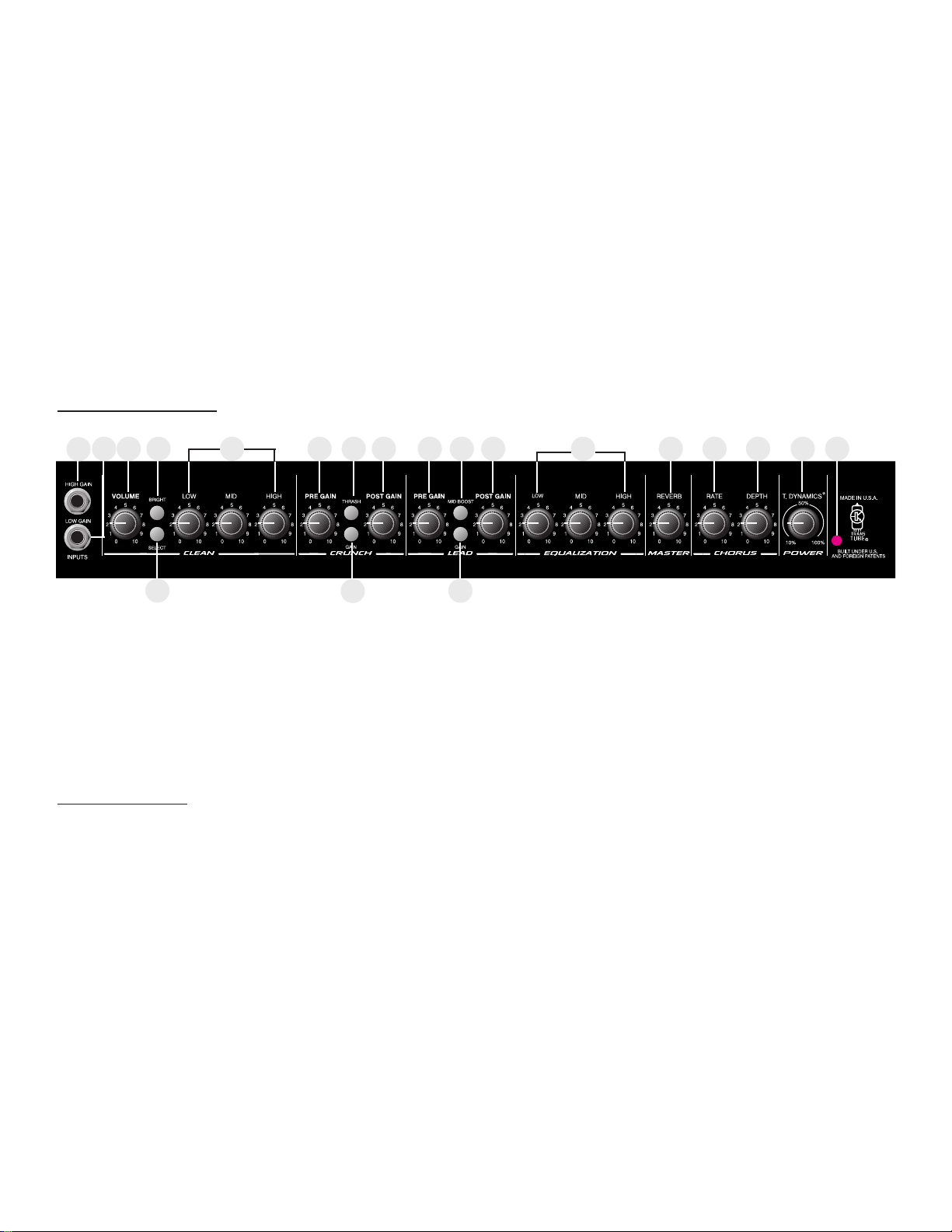
FRONT PANEL
Hi Gain Input (1)
Used for most electric guitars. It is 6 dB louder than the Low Gain input.
Low Gain (2)
Provided for instruments that have extremely high outputs, which can result in overdriving (distorting) the High Gain input. If both inputs are used simultaneously, the output levels are the same (both
are low gain).
Clean Channel
Volume (3)
Controls the output level of the Clean channel.
Bright Switch (4)
When activated (pressed in), this switch provides a 6 dB boost to the extreme high frequency
portion of your signal.
Select Switch (5)
This switch selects between the Clean and Lead channels. The ÒinÓ position selects the Lead
channel and the ÒoutÓ position selects the Clean. Channel selection may also be achieved by
using the remote footswitch. The Select Switch must be in the ÒinÓ position for the footswitch to
operate. Use of the footswitch will also allow you to select between the Crunch and Lead channels.
Low, Mid, and High EQ (6)
This section is a passive tone control for the clean channel. Adjusting these knobs clockwise will
pass more low, mid, or high frequency content of the Clean channel to the internal power amps.
4
1
5
3 4 6 7 8 10 11 12 14 15 16 17 18 19 202
9
13
Page 5

Crunch Channel
Pregain (7)
Controls the input level of the Crunch channel. Adjusting this control clockwise will increase the input
level, thus increasing distortion.
Thrash Switch (8)
When activated (in), this switch attenuates a preset portion of the mid range resulting in a more
ÒheavyÓ sound and an apparent increase in distortion.
Gain Switch (9)
When activated (in), this switch boosts the pregain of the Crunch channel resulting in increased distortion. This effect is often used to get intentional feedback and increased sustain.
Post Gain (10)
Controls the output level of the Crunch channel. Adjusting this control clockwise will result in
increased volume. The desired tone and distortion level should be obtained prior to adjusting this
control for proper level. Consider this control the volume control for the Crunch channel.
Lead Channel
Pregain (11)
Controls the input level of the Lead channel. Adjusting this control clockwise will increase the input
level, thus increasing distortion.
Mid Boost Switch (12)
When activated (in), this switch boosts the mid frequencies. This effect is often desired when miking
an amp that is producing distorted guitar signals. Selecting the Mid Boost will bring the signal up in
the overall mix during lead passages.
Gain Switch (13)
When activated (in), this switch boosts the pregain of the Lead channel resulting in increased distortion. This effect is often used to get intentional feedback and increased sustain.
Post Gain (14)
Controls the output level of the Lead channel. Adjusting this control clockwise will result in increased
volume. The desired tone and distortion level should be obtained prior to adjusting this control for
proper level. Consider this control the volume control for the Lead channel.
Low, Mid, and High EQ (15)
This section is a passive tone control for the Crunch and Lead channels. Adjusting these knobs
clockwise will pass more low, mid, or high frequency content of these to the internal power amps .
Reverb (16)
Adjusting this control clockwise will result in more reverb content in the output of the amp regardless
of the channel. The reverb can be defeated completely by rotating the control counter clockwise.
Rate (17)
Adjusting this control clockwise will result in an increase in the sweep rate (frequency) of the
chorus effect. The chorus can only be disabled from the footswitch.
5
Page 6

Depth (18)
Adjusting this control clockwise will result in an increase in the depth or intensity of the chorus
effect. This control adjusts the amount of chorus you actually hear from the output of the amp.
T. Dynamics¨(19)
This control adjusts the usable power of the internal power amps from 10% (counter clockwise) to
100% (clockwise). Rotating this control clockwise will result in more available power. This effect is
often set to lower levels in order for the power amp compression simulation to be more apparent,
allowing you to overdrive the power amp at lower volume levels, achieving a tube power amp
clipping/compression quality.
Power LED (20)
Illuminates when power is supplied to the amp. If this LED is lit, the amp is on.
REAR PANEL
Power Switch (21)
Placing this switch in the ÒONÓ position will result in power being supplied to the unit. The Power
LED (20) will illuminate when the amp is on.
Stereo Headphone (22)
This 1/4Ó stereo output jack is designed to accommodate standard, stereo headphones. Plugging
a set of headphones into this jack will disconnect the signal going to the power amplifiers of the
unit, and no output can be heard from the unitÕs speakers. This feature provides an excellent
practice tool.
Power Amp In (23)
These left and right mono 1/4" jacks provide an input to each of the power amplifiers. When used
in conjunction with the Preamp Out jacks (24), a stereo effects loop is formed allowing the use
of stereo delays and various effects.
Preamp Out (24)
These left and right mono 1/4" jacks provide an output from each of the preamps. When used
in conjunction with the Power Amp In jacks (23), a stereo effects loop is formed allowing the use
of stereo delays and various effects.
Remote Switch (25)
This jack is provided for the connection of the supplied footswitch. The footswitch is a multi-function
type allowing you to select Clean, Crunch, or Lead and to defeat the Chorus effects. To use the
footswitch ensure that the footswitch plug is inserted fully into the jack and that the Select switch is
pressed in (down position) on the front panel.
6
21
26
22 23 24 23 24 25
Page 7

AC LINE CORDÑ120 V PRODUCTS ONLY (26)
For you safety, we have incorporated a three-wire line (mains) cable with proper grounding
facilities. It is not advisable to remove the ground pin under any circumstances. If it is
necessary to use the equipment without proper grounding facilities, suitable grounding adapters
should be used. Less noise and greatly reduced shock hazard exists when the unit is operated with
the proper grounded receptacles.
NOTE: FOR UK ONLY
As the colors of the wires in the mains lead of this apparatus may not correspond with the
colored markings identifying the terminals in your plug, proceed as follows:
¥ The wire which is colored green and yellow must be connected to the terminal which is
marked by the letter E, or by the earth symbol, or colored green or green and yellow.
¥ The wire which is colored blue must be connected to the terminal which is marked with the
letter N, or the color black.
¥ The wire which is colored brown must be connected to the terminal which is marked with
the letter L, or the color red.
7
Page 8
8
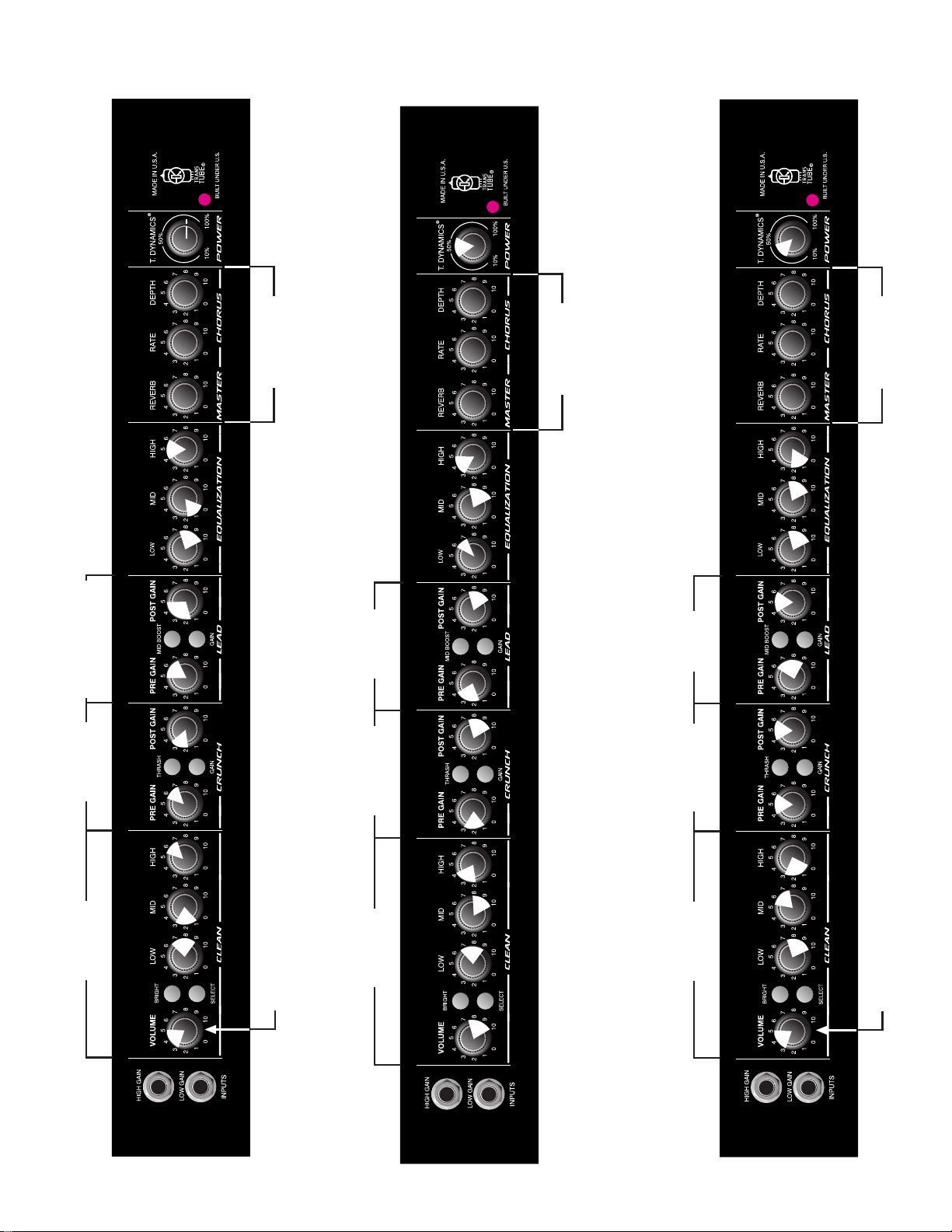
RECOMMENDED SETTINGS:
MODERATE
DISTORTION
METAL
To Taste
In
Out
LEAD
BLUES
In
In
BLUES
RHYTHM
In
Out
Out
Out
To Taste
JAZZ
LEAD
JAZZ
RHYTHM
In
Out
In
Out
To Taste
CLEAN
JAZZ
CLEAN
BLUES
In
In
To Taste
Out
In
CLEAN
In
In
To Taste
Page 9

(ALL MEASUREMENTS @ 120 V AC, 60HZ)
POWER AMPLIFIER SECTION
RATED OUTPUT POWER:
Power specs measured with T. Dynamics @ 100%
(5% THD, 1 kHz, 120 V AC)
50 W RMS per channel, into 8 ohms
FREQUENCY RESPONSE:
Stereo mode into 8 ohm, power amp inputs
-3 dB, +2 dB, 70 Hz to 20 kHz, @ 45 W RMS into
8 ohms
HUM AND NOISE:
Unweighted, 20 Hz to 22 kHz
Greater than 90 dB, both channels
POWER CONSUMPTION:
Domestic Model: 120 V AC, 60 Hz, 2.5A, 300 W
Export Model: 220 to 240 V AC, 50/60 Hz, 300 W
PREAMP SECTION
(The following specs are measured @ 1 kHz with the controls
preset as follows:)
Push Bright, off (out)
Channel Select Clean (out)
Low and High @ 10
Mid @ 0
Crunch Pre and Post Gain @ 10
Gain and Thrash, off (out)
Lead Pre and Post Gain @ 10
Gain and Mid Boost, off (out)
Normal levels are with normal volume @ 5
Minimum levels are with clean volume @ 10
PREAMP HIGH GAIN INPUT:
Impedance: High-Z, 1 M ohm
Nominal Input Level: -12 dBV, 250 mV RMS
Minimum Input Level: -22 dBV, 79 mV RMS
Maximum Input level: 0 dBV, 1 V RMS
PREAMP LOW GAIN INPUT:
Impedance: High-Z, 44 k ohms
Nominal Input Level: -6 dBV, 500 mV RMS
Minimum Input Level: -16 dBV, 158 mV RMS
Maximum Input level: 6 dBV, 2 V RMS
PREAMP OUTPUT:
Load Impedance: 300 ohm or greater
Nominal Output Level: 0 dBV, 1 V RMS
POWER AMP INPUT:
Impedance: High-Z, 30 k ohms
Designed Input Level: 0 dBV, 1 V RMS
(Switching jack provides preamp output to power amp input
connection when not used.)
SYSTEM HUM AND NOISE @ NOMINAL
INPUT LEVEL
UNWEIGHTED, 20 Hz to 22 kHz
Greater than 75 dB, below rated power
EQUALIZATION:
Special low, mid and high passive type EQ
Push Bright: +4 dBV @ 2 kHz, (Clean channel)
Push Thrash: -6 dBV notch 1 kHz, (Crunch channel)
Push Mid boost: +3 dBV band pass 1 kHz, (Lead channel)
Push Gain: Increase gain both Lead and Crunch channels
EXTERNAL FOOT SWITCH FUNCTIONS:
Lead/Crunch: Selects lead or crunch channel.
Bypass/Clean: Lead and Crunch channel defeat
(channel switch ÒINÓ)
Select/Chorus: Defeat Chorus
DIMENSIONS AND WEIGHT (H x W x D):
18.5" x 23.375" x 11.375"
47cm x 10.60cm x 29cm
9
TRANSCHORUSª210 SPECIFICATIONS
Page 10
EQUALIZATION
TransChorus
ª
210 BLOCK DIAGRAM
10
STEREO
CHORUS
LEVEL
DEPTH
REVERB
FOOT
SWITCH
RATE
PREGAIN
PREGAIN
OUT
HIGHMIDLOW
AMP IN
PREGAIN
OUT
PREGAIN
AMP IN
TONE
VOLUME
CLEAN
HIMIDLO
CLEAN
PUSH
BRIGHT
PUSH
MID
BOOST
POST
HIGH
GAIN AMP
LEAD
SWITCH
LOGIC
SWITCH LOGIC
CLEAN/ULTRA
LEAD
PREGAIN
LEAD
PUSH
BRIGHT
LEAD
FOOT
PUSH
CHANNEL
SWITCH
FOOT
SWITCH
POST
PUSH
PREGAIN
CRUNCH
CRUNCH
THRASH
PREGAIN
POWER
AMP
SPEAKER
¨
T. DYNAMICS
POWER
AMP
SPEAKER
¨
T. DYNAMICS
1st
GAIN STAGE
INPUTS
Page 11

IMPORTANT SAFETY INSTRUCTIONS
WARNING: When using electric products, basic cautions should always be followed, including the following:
1. Read these instructions.
2. Keep these instructions.
3. Heed all warnings.
4. Follow all instructions.
5. Do not use this apparatus near water. For example, near or in a bathtub, swimming pool, sink, wet basement, etc.
6. Clean only with a damp cloth.
7. Do not block any of the ventilation openings. Install in accordance with manufacturerÕs instructions. It should not be placed flat against a wall
or placed in a built-in enclosure that will impede the flow of cooling air.
8. Do not install near any heat sources such as radiators, heat registers, stoves or other apparatus (including amplifiers) that produce heat.
9. Do not defeat the safety purpose of the polarized or grounding-type plug. A polarized plug has two blades with one wider than the other. A
grounding type plug has two blades and a third grounding plug. The wide blade or third prong is provided for your safety. When the provided
plug does not fit into your inlet, consult an electrician for replacement of the obsolete outlet. Never break off the grounding. Write for our free
booklet ÒShock Hazard and GroundingÓ. Connect only to a power supply of the type marked on the unit adjacent to the power supply cord.
10. Protect the power cord from being walked on or pinched, particularly at plugs, convenience receptacles, and the point they exit from the
apparatus.
11. Only use attachments/accessories provided by the manufacturer.
12. Use only with a cart, stand, tripod, bracket, or table specified by the manufacturer, or sold with the apparatus. When a cart is used, use caution
when moving the cart/apparatus combination to avoid injury from tip-over.
13. Unplug this apparatus during lightning storms or when unused for long periods of time.
14. Refer all servicing to qualified service personnel. Servicing is required when the apparatus has been damaged in any way, such as power-
supply cord or plug is damaged, liquid has been spilled or objects have fallen into the apparatus, the apparatus has been exposed to rain or
moisture, does not operate normally, or has been dropped.
15. If this product is to be mounted in an equipment rack, rear support should be provided.
16. Exposure to extremely high noise levels may cause a permanent hearing loss. Individuals vary considerably in susceptibility to noise-induced
hearing loss, but nearly everyone will lose some hearing if exposed to sufficiently intense noise for a sufficient time. The U.S. GovernmentÕs
Occupational and Health Administration (OSHA) has specified the following permissible noise level exposures:
Duration Per Day In Hours Sound Level dBA, Slow Response
890
692
495
397
2 100
1 1/2 102
1 105
1/2 110
1/4 or less 115
According to OSHA, any exposure in excess of the above permissible limits could result in some hearing loss. Ear plugs or protectors to the ear
canals or over the ears must be worn when operating this amplification system in order to prevent a permanent hearing loss, if exposure is in excess
of the limits as set forth above. To ensure against potentially dangerous exposure to high sound pressure levels, it is recommended that all persons
exposed to equipment capable of producing high sound pressure levels such as this amplification system be protected by hearing protectors while
this unit is in operation.
SAVE THESE INSTRUCTIONS!
11
Page 12

TransChorusª210
Felicitaciones por su compra del amplificador Peavey TransChorusª210. Este amplificador combina
la emulaci—n de tubos de vac’o Transtube¨patentada de Peavey con los œltimos avances en cuanto
a dise–o de amplificadores corales. Si nunca us— un amplificador Peavey TransTube¨para ejecutar,
ahora tiene una oportunidad para deleitarse. La tecnolog’a Transtube¨produce un tono tan similar a
la de los tubos de vac’o que enga–a hasta a los o’dos con m‡s experiencia. Los amplificadores
corales de Peavey han sido los m‡s vendidos durante a–os ya que ofrecen una variedad de
sonidos corales que abarcan desde una ligera insinuaci—n hasta un gran torbellino.
Otras de las funciones que encontrar‡ en el amplificador coral TransChorusª210 son
reverberaci—n, tres canales independientes, amplificador de potencia estereof—nico, dos conjuntos
de ecualizaci—n y circuitos del amplificador de potencia Peavey T. Dynamics¨. Reœna todas estas
funciones en el compacto gabinete del TransChorusª210 y obtendr‡ un amplificador combinado,
port‡til y vers‡til, con el que podr‡ responder a diversas exigencias de ejecuci—n. Como sabemos
que desea utilizarlo inmediatamente, hemos incluido una secci—n de ÒInicio r‡pidoÓ y otra de
ÒConfiguraciones recomendadasÓ. Seguramente lo ayudar‡n a que comience a practicar ya mismo.
Sin embargo, es importante que ante todo lea las precauciones de seguridad. Examine este manual
y encuentre los siguientes iconos de seguridad.
A continuaci—n de cada icono de seguridad encontrar‡ una advertencia. Lea la advertencia con
cuidado antes de continuar leyendo. DespuŽs de haber le’do todas las advertencias, consulte la
secci—n ÒInicio r‡pidoÓ a continuaci—n, si as’ lo desea. Recomendamos que lea este manual
completamente para comprender cabalmente las funciones de cada caracter’stica.
Inicio r‡pido Ñ ÁS—lo deseo ejecutar!
Esta secci—n adopta el mŽtodo de Òsaltar y mojarse los piesÓ. Si alguna parte le parece confusa,
consulte las secciones m‡s detalladas que encontrar‡ a continuaci—n.
Paso 1. Asegœrese de que ha le’do y comprendido todas las advertencias de seguridad del manual.
Por su seguridad y por la de su amplificador, resulta fundamental que siga esas precauciones.
Paso 2. Con el amplificador apagado, enchufe el cable de alimentaci—n en la fuente de
alimentaci—n apropiada, indicada en la parte posterior de la unidad, cerca del dispositivo para
sujetar el cable.
Paso 3. Enchufe la guitarra en la entrada de alta o de baja ganancia y gire todas las perillas hacia
la izquierda, a la posici—n "0".
Paso 4. Siga las instrucciones de la secci—n "Configuraciones recomendadas" de la p‡gina 7 hasta
encontrar el tipo de tono que m‡s se asemeja al que usted desea obtener.
Paso 5. Lleve las perillas de la parte frontal de la unidad a la posici—n que corresponda a la
configuraci—n que seleccion—.
ESPA„OL
12
Page 13

Paso 6. Enchufe el conmutador de pedal en el enchufe hembra del conmutador remoto situado en
la parte posterior de la unidad.
Paso 7. Reduzca el volumen de la guitarra y utilice el interruptor de alimentaci—n situado en la parte
posterior de la unidad para encender el amplificador.
Paso 8. Aumente gradualmente el volumen de la guitarra hasta alcanzar el valor m‡ximo o el nivel o
tono con el que se sienta c—modo.
Paso 9. Experimente con el conmutador de pedal para familiarizarse con el mŽtodo de selecci—n de
los tres canales diferentes.
Nota: Debe oprimir el bot—n de selecci—n del amplificador (posici—n hacia abajo) si desea que el
conmutador de pedal estŽ operativo.
Paso 10. Si desea ajustar el nivel total de cada canal, use la perilla de volumen para el canal limpio
y los controles de posganancia para los canales de efectos estridentes y l’der.
Paso 11. Para ajustar el nivel de distorsi—n en los canales de efectos estridentes y l’der, use la
perilla de preganancia. Si gira la perilla hacia la derecha, aumentar‡ la distorsi—n.
Paso 12. Seguramente ya puede usar el amplificador. Oprima los diferentes botones para o’r su
efecto en los tonos. Gire las perillas de reverberaci—n o de coro y profundidad para sentir su efecto
tambiŽn. Algo aœn m‡s importanteÉ lea el resto de este manual.
PANEL FRONTAL
Consulte los diagramas del panel delantero en
la secci—n de inglŽs de est manual.
Entrada de alta ganancia (1)
Funci—n que se emplea con la mayor’a de las guitarras. Tiene 6 dB m‡s intensidad de volumen que
la entrada de baja ganancia.
Baja ganancia (2)
Se provee para aquellos instrumentos con salidas extremadamente altas, que pueden sobreexcitar
(distorsionar) la entrada de alta ganancia. Si se emplean ambas entradas simult‡neamente, los
niveles de salida son los mismos (ambos son de baja ganancia).
Canal limpio
Volumen (3)
Controla el nivel de la salida del canal limpio.
Conmutador de brillo (4)
Cuando se activa (se oprime), este conmutador provee un refuerzo de 6 dB a la parte de alta
frecuencia extrema de la se–al.
Conmutador de selecci—n (5)
Este conmutador permite seleccionar entre los canales limpio y l’der. La posici—n Òhacia adentroÓ
selecciona el canal l’der y la posici—n Òhacia afueraÓ, el limpio. TambiŽn se pueden seleccionar
canales utilizando el conmutador de pedal remoto. El conmutador de selecci—n debe estar en la
13
Page 14

posici—n Òhacia adentroÓ para que el conmutador de pedal estŽ operativo. El conmutador de pedal
tambiŽn le permitir‡ seleccionar entre los canales de efectos estridentes y l’der.
Ecualizaci—n de bajos, medios y altos (6)
Esta secci—n corresponde al control de tonos pasivos del canal limpio. Si lleva estas perillas hacia
la derecha pasar‡ m‡s contenido de bajas, medias y altas frecuencias del canal
limpio a los amplificadores de potencia internos.
Canal de efectos estridentes
Preganancia (7)
Controla el nivel de entrada del canal de efectos estridentes. Lleve este control hacia la derecha
para aumentar el nivel de entrada, y as’ aumentar la distorsi—n.
Conmutador ÒthrashÓ (filtro parcial) (8)
Cuando est‡ activado (hacia adentro), este conmutador atenœa una porci—n preprogramada del
rango medio, lo que resulta en un sonido m‡s ÒpesadoÓ y un aparente aumento en la distorsi—n.
Conmutador de ganancia (9)
Cuando est‡ activado (hacia adentro), este conmutador refuerza la preganancia del canal de
efectos estridentes lo que resulta en mayor distorsi—n. Con frecuencia este efecto se usa para
obtener retroalimentaci—n voluntaria y mayor sostenimiento.
Posganancia (10)
Controla el nivel de salida del canal de efectos estridentes. Lleve este control hacia la derecha para
aumentar el volumen. Para obtener el nivel apropiado, deben obtenerse el tono y el nivel de
distorsi—n deseados antes de ajustar este control. Considere a este control como el de volumen
para el canal de efectos estridentes.
Canal l’der
Preganancia (11)
Controla el nivel de entrada del canal l’der. Lleve este control hacia la derecha para aumentar el
nivel de entrada y as’ aumentar la distorsi—n.
Conmutador de refuerzo de medios (12)
Cuando est‡ activado (hacia adentro), este conmutador refuerza las frecuencias medias. Con
frecuencia se necesita este efecto cuando se usa para un micr—fono un amplificador que produce
se–ales distorsionadas de guitarra. Cuando se selecciona el refuerzo de medios aumentar‡ la se–al
de la mezcla total durante las partes l’der.
Conmutador de ganancia (13)
Cuando est‡ activado (hacia adentro), este conmutador refuerza la preganancia del canal l’der lo
que resulta en mayor distorsi—n. Con frecuencia este efecto se usa para obtener retroalimentaci—n
intencional y mayor sostenimiento.
Posganancia (14)
Controla el nivel de salida del canal l’der. Lleve este control hacia la derecha para aumentar el
volumen. Para obtener el nivel apropiado, deben obtenerse el tono y el nivel de distorsi—n deseados
antes de ajustar este control. Considere a este control como el de volumen para el canal l’der.
14
Page 15
Ecualizaci—n de bajos, medios y altos (15)
Esta secci—n corresponde al control de tonos pasivos de los canales de efectos estridentes y l’der.
Si lleva estas perillas hacia la derecha pasar‡ m‡s contenido de bajas, medias y altas frecuencias a
los amplificadores de potencia internos.
Reverberaci—n (16)
Lleve este control hacia la derecha para obtener m‡s contenido de reverberaci—n en la salida del
amplificador independientemente del canal. Si desea anular completamente la reverberaci—n, gire el
control hacia la izquierda.
Frecuencia (17)
Lleve este control hacia la derecha para aumentar la frecuencia de barrido del efecto coral. El coral
s—lo puede desactivarse con el conmutador de pedal.
Profundidad (18)
Lleve este control hacia la derecha para aumentar la profundidad o intensidad del efecto coral. Este
control ajusta la cantidad de coral que se oye en realidad como salida del amplificador.
T. Dynamics¨(19)
Este control ajusta la potencia disponible de los amplificadores de potencia internos desde el 10%
(hacia la izquierda) al 100% (hacia la derecha). Gire este control hacia la derecha para tener m‡s
potencia disponible. Con frecuencia este efecto se configura con niveles m‡s bajos a fin de que
resulte m‡s evidente la simulaci—n de compresi—n del amplificador de potencia y as’ permitir que
usted sobreexcite el amplificador de potencia con niveles de volumen m‡s bajos y as’ pueda lograr
una calidad de recorte de se–al/compresi—n de un amplificador de potencia con tubos de vac’o.
LED Indicador de encendido (20)
Se ilumina cuando el amplificador recibe alimentaci—n. Si este indicador LED est‡ iluminado, el
amplificador est‡ encendido.
PANEL POSTERIOR
Interruptor de encendido (21)
Lleve este conmutador a la posici—n de ÒencendidoÓ para que la unidad reciba alimentaci—n. El LED
indicador de encendido (20) se iluminar‡ cuando el amplificador estŽ encendido.
Auriculares estereof—nicos (22)
Este enchufe hembra de salida estereof—nico de 1/4 pulg. fue dise–ado para utilizar con auriculares
estereof—nicos est‡ndar. Enchufe un par de auriculares en este enchufe hembra para desconectar
la se–al de los amplificadores de potencia de la unidad y no oir‡ la salida por los altavoces de la
unidad. Esta funci—n ofrece una excelente herramienta para la pr‡ctica.
21
26
22 23 24 23 24 25
15
Page 16

Entrada del amplificador de potencia (23)
Estos enchufes hembra monoaurales izquierdo y derecho de 1/4 pulg. constituyen una entrada para
cada uno de los amplificadores de potencia. Cuando se usan junto con los enchufes hembra de
salida del preamplificador (24), se forma un circuito de efectos estereof—nicos que permite emplear
retardos estereof—nicos y diversos efectos.
Salida del preamplificador (24)
Estos enchufes hembra monoaurales izquierdo y derecho de 1/4 pulg. proveen una salida para
cada uno de los preamplificadores. Cuando se usan junto con los enchufes hembra de entrada del
amplificador de potencia (23), se forma un circuito de efectos estereof—nicos que permite emplear
retardos estereof—nicos y diversos efectos.
Interruptor remoto (25)
Este enchufe hembra se provee para conectar el conmutador de pedal provisto. El conmutador de
pedal es del tipo multifunci—n, que le permite seleccionar los canales limpio, de efectos estridentes
o l’der y anular el efecto coral. Para usar el conmutador de pedal, asegœrese de que el conector del
mismo estŽ completamente introducido en el enchufe hembra y que el conmutador de selecci—n en
el panel frontal estŽ en la posici—n hacia adentro.
CABLE DE LêNEA DE ALIMENTACIîN DE CA Ñ SîLO PARA PRODUCTOS DE 120 V (26)
Para su seguridad, hemos incorporado un cable de alimentaci—n (de red) trifilar,
correctamente preparado para conexi—n a tierra. En ninguna circunstancia se debe eliminar el
terminal de conexi—n a tierra. Si es necesario utilizar el equipo sin los dispositivos de conexi—n a
tierra apropiados, se deber‡n emplear adaptadores en su lugar. Cuando la unidad se usa con los
recept‡culos conectados correctamente a tierra, disminuye el ruido y se reduce considerablemente
el riesgo de descarga elŽctrica.
16
Page 17

(TODAS LAS MEDIDAS SE ESPECIFICAN
PARA 120 V CA, 60 Hz)
SECCIîN DEL AMPLIFICADOR DE POTENCIA
Potencia de salida nominal:
Las especificaciones de potencia se determinaron con
T. Dynamics a 100%
(5% THD, 1 kHz, 120 V CA)
50 Wef por canal en 8 W
Respuesta de frecuencia:
Modo estereof—nico en 8 W, entradas del amplificador
de potencia Ð3 dB, +2 dB, de 70 Hz a 20 kHz, a
45 Wef en 8 W
Zumbido y ruido:
Sin ponderaci—n, de 20 Hz a 22 kHz
Mayor que 90 dB, ambos canales
Requisitos de alimentaci—n:
Modelo estadounidense: 120 V CA, 60 Hz, 2,5 A, 300 W
Modelo internacional: de 220 a 240 V CA, 50/60 Hz, 300 W
SECCIîN DEL PREAMPLIFICADOR
(Las siguientes especificaciones se determinaron a 1 kHz con los
controles preprogramados de la siguiente manera:)
Conmutador de brillo, apagado (hacia afuera)
Selecci—n de canal limpio (hacia afuera)
Altas y bajas a 10
Medias a 0
Pre y posganancia de efectos estridentes a 10
Ganancia y "thrash", apagado (hacia afuera)
Pre y posganancia del canal l’der a 10
Ganancia y refuerzo de medios, apagado (hacia afuera)
Los niveles normales corresponden a un volumen normal de 5
Los niveles m’nimos corresponden a un volumen limpio de 10
Entrada de alta ganancia del preamplificador:
Impedancia: Alta impedancia, 1 MW
Nivel de entrada nominal: Ð12 dBV, 250 mVef
Nivel de entrada m’nimo: Ð22 dBV, 79 mVef
Nivel de entrada m‡ximo: 0 dBV, 1 Vef
Entrada de baja ganancia del preamplificador:
Impedancia: Alta impedancia, 44 kW
Nivel de entrada nominal: Ð6 dBV, 500 mVef
Nivel de entrada m’nimo: Ð16 dBV, 158 mVef
Nivel de entrada m‡ximo: 6 dBV, 2 Vef
Salida del preamplificador:
Impedancia de carga: 300 W o mayor
Nivel de salida nominal: 0 dBV, 1 Vef
Entrada del amplificador de potencia:
Impedancia: Alta impedancia, 30 kW
Nivel de entrada de dise–o: 0 dBV, 1 Vef
(Cuando se usa, el enchufe hembra de conmutaci—n
provee la conexi—n entre la salida del preamplificador
y la entrada del amplificador de potencia.)
ZUMBIDO Y RUIDO DEL SISTEMA AL NIVEL
DE ENTRADA NOMINAL
Sin ponderar, de 20 Hz a 22 kHz
M‡s de 75 dB por debajo de la potencia nominal
ECUALIZACIîN:
Ecualizaci—n tipo pasiva especial para frecuencias
bajas, medias y altas
Conmutador de brillo: +4 dBV a 2 kHz, (canal limpio)
ÒThrashÓ (filtro parcial): Ð6 dBV de muesca 1 kHz,
(canal de efectos estridentes)
Refuerzo de medios: +3 dBV pasabanda 1 kHz,
(canal l’der)
Ganancia: Aumenta la ganancia de los canales l’der y
de efectos estridentes
FUNCIONES DEL CONMUTADOR DE PEDAL
EXTERNO:
Canal l’der/de efectos estridentes: Selecciona el canal
correspondiente.
Derivaci—n/Limpio: Anula el canal l’der y de efectos
estridentes (conmutador de canal "hacia adentro")
Selecci—n/Coral: Anula el coral
DIMENSIONES Y PESO (Alto x ancho x profundidad):
47 x 59 x 29 cm
17
ESPECIFICACIONES DEL AMPLIFICADOR TRANSCHORUSª210
Page 18

18
INSTRUCCIONES DE SEGURIDAD IMPORTANTES
ADVERTENCIA: Al utilizar productos elŽctricos se deben respetar las precauciones b‡sicas, que incluyen las siguientes:
1. Lea estas instrucciones.
2. Conserve estas instrucciones.
3. Preste atenci—n a todas las advertencias.
4. Respete todas las instrucciones.
5. No utilice este aparato cerca del agua. Por ejemplo, cerca o dentro de ba–eras, piscinas, lavaderos, s—tanos hœmedos, etc.
6. Limpie el aparato solamente con un trapo hœmedo.
7. No bloque ninguna de las aberturas de ventilaci—n. Instale el aparato de acuerdo con las instrucciones del fabricante. No debe ser colocado contra la pared sin separaci—n o dentro de una cubierta que impida el flujo de aire de ventilaci—n.
8. No instale el aparato cerca de fuentes de calor, tales como radiadores, registros de calefacci—n, estufas u otros aparatos que produzcan
calor (incluso amplificadores).
9. No anule la funci—n de seguridad de los enchufes de tipo polarizado o con toma de tierra. El enchufe de tipo polarizado tiene dos patas
planas, una m‡s ancha que la otra. El enchufe con toma de tierra tiene dos patas planas y un tercer terminal de toma de tierra. La pata m‡s
ancha o el tercer terminal se proporcionan para su seguridad. Cuando el enchufe provisto no sirve para su recept‡culo de alimentaci—n,
consulte a un electricista para reemplazar el recept‡culo obsoleto. No interrumpa nunca la toma de tierra. Escr’banos y solicite nuestro
folleto gratuito ÒRiesgo de descarga elŽctrica y puesta a tierraÓ. Conecte el aparato œnicamente a una fuente de alimentaci—n del tipo marcado en la unidad, cerca del cable de alimentaci—n elŽctrica.
10. Proteja el cable de alimentaci—n para que no lo pise o estrangule, especialmente en los enchufes, tomacorrientes y en el punto de salida
del aparato.
11. Utilice s—lo aditamentos/accesorios provistos por el fabricante.
12. Utilice s—lo carros, plataformas, tr’podes, soportes o mesas especificadas por el fabricante o vendidas con el aparato. Cuando se utiliza un
carro, sea precavido al mover la combinaci—n carro/aparato, para evitar lesiones en caso de vuelcos.
13. Desenchufe este aparato durante tormentas elŽctricas o mientras no se lo utilice durante per’odos prolongados.
14. Conf’e todas las reparaciones a personal tŽcnico calificado. Se requiere servicio cuando el aparato ha sido da–ado de alguna forma, como
cuando se aver’an el cable de alimentaci—n o el enchufe, se derraman l’quidos o caen objetos dentro del aparato o el mismo se expuso a la
lluvia o la humedad, no funciona normalmente o se lo dej— caer.
15. Si este producto se monta en un bastidor para equipos, se debe instalar un soporte posterior.
16. La exposici—n a niveles de ruido extremadamente altos puede provocar pŽrdidas auditivas permanentes. La susceptibilidad de los individuos a las pŽrdidas auditivas inducidas por ruido var’a considerablemente, pero casi todos sufrir‡n alguna pŽrdida auditiva si se exponen a
un nivel de ruido lo suficientemente intenso, durante un per’odo suficiente. La Administraci—n del Trabajo y la Salud del gobierno de los
Estados Unidos (OSHA), ha especificado los siguientes niveles permitidos de exposici—n al ruido:
Duraci—n diaria en horas Nivel de sonido en dBa, respuesta lenta
890
692
495
397
2 100
1 1/2 102
1 105
1/2 110
1/4 o menos 115
Segœn la administraci—n OSHA, toda exposici—n que exceda los l’mites permitidos indicados m‡s arriba, puede producir alguna pŽrdida auditiva.
Para evitar pŽrdidas auditivas permanentes, si la exposici—n excede los l’mites precedentes cuando se opera este equipo de sonido, se deben utilizar
tapones o protectores de los canales auditivos o por sobre los o’dos. Para asegurarse contra la exposici—n a niveles de presi—n sonora peligrosos, se
recomienda que mientras esta unidad estŽ funcionando, todas las personas expuestas a equipos capaces de producir niveles de presi—n sonora altos
como este sistema amplificador, estŽn protegidas mediante protectores auditivos.
ÁCONSERVE ESTAS INSTRUCCIONES!
Page 19

TransChorusª210
Nous vous fŽlicitons pour lÕachat de cet amplificateur Peavey TransChorusª210. Le TransChorus
ª
210 associe lÕŽmulation des lampes brevetŽe TransTube¨aux design le plus moderne en mati•re de
chorus. La technologie TransTube¨reprŽsente des annŽes de recherche sur lÕŽmulation du Óson
lampeÓ et sur les amplis pour guitare en gŽnŽral. Le prŽampli a ŽtŽ dŽveloppŽ afin de recrŽer toutes
les caractŽristiques du rendu harmonique et de la distorsion de lampes. LÕampli de puissance
apporte la compression et la distorsion subtile des Žtages de puissance ˆ tubes. La rŽputation des
amplificateurs Chorus Peavey nÕest plus ˆ faire et comme toujours, vous disposez dÕun chorus
permettant une effet discret ou un effet tridimensionnel saisissant.
Le TransChorusª210 dispose par ailleurs de trois canaux sŽparŽs, dÕune rŽverbe et dÕun
amplificateur de puissance stŽrŽo ŽquipŽ dÕun contr™le T. Dynamics¨. Avec son format 2x10 pouces,
le TransChorusª210 constitue un outil compact et versatile pouvant sÕadapter ˆ toutes les
situations. Les sections ÒDŽmarrage rapideÓ et ÒRecommended SettingsÓ vous permettent de vous
familiariser rapidement avec lÕamplificateur. Cependant, il est important que vous lisiez les
prŽcautions dÕemploi de lÕappareil. RepŽrez les ic™nes suivant dans ce manuel:
Lisez chacun des paragraphes signalŽs par ces ic™nes. Vous pouvez alors revenir ˆ la section
ÒDŽmarrage rapideÓ. Nous vous recommandons de lire le manuel dans sa totalitŽ afin de
comprendre toutes les fonctions et possiblitŽs quÕoffre cet amplificateur.
DŽmarrage rapide
Cette section vous permet de rapidement vous familiariser avec le TransChorusª210. Si quelque
chose vous Žchappe, rŽfŽrez-vous ˆ la section plus dŽtaillŽe suivante.
1. Assurez-vous que vous avez lu et compris toutes les prŽcautions dÕemploi de ce manuel. Il est
important de respecter ces prŽcautions pour votre sŽcuritŽ et celle de votre amplificateur.
2. LÕamplificateur Žtant hors-tension, connectez le cordon dÕalimentation ˆ une source de
courant dont les caractŽristiques correspondent aux inscriptions situŽes prŽs de la prise IEC.
3. Branchez votre guitare dans lÕentrŽe Hi Gain ou lÕentrŽe Lo Gain, tous les rŽglages Žtant en
position Ò0Ó .
4. Dans la section ÒRecommended SettingsÓ en page 7, trouvez le type de tonalitŽ qui se rapproche
le plus de celui que vous recherchez.
5. Placez les rŽglages de lÕappareil comme indiquŽ pour obtenir le son recherchŽ.
6. Branchez votre footswitch dans la prise Remote Switch ˆ lÕarri•re de lÕamplificateur.
7. RŽglez le volume de lÕamplificateur ˆ Ò0Ó.
8. Mettez lÕappareil en marche ˆ lÕaide de lÕinterrupteur situŽ en face arri•re.
9. Utilisez le footswitch pour changer de canal.
Note: Le bouton de sŽlection du canal doit •tre enfoncŽ pour que le footswitch fonctionne.
FRAN‚AIS
19
Page 20

10. Utilisez le contr™le de Volume pour dŽterminer le volume du canal Clean et utilisez les contr™les
Post Gain pour les canaux Crunch et Lead.
11. Utilisez le contr™le Pre Gain pour dŽterminer la quantitŽ de distorsion des canaux Crunch et
Lead. Tourner le contr™le dans le sens horaire pour augmenter le niveau de saturation.
12. Jouez et utilisez les diffŽrents sŽlecteurs de lÕamplificateur afin de comprendre leur effet sur le
son de lÕamplificateur. Variez le taux de rŽverbe ainsi que la profondeur et la vitesse du Chorus pour
vous familiariser avec leur effet. NÕOUBLIEZ PAS DE LIRE CE MANUEL.
FACE AVANT
Veuillez-vous rŽfŽrer au <<front panel>> art situŽ dans
la section en langue anglaise de ce manual.
1. EntrŽe HIGH GAIN
Utilisez cette entrŽe pour la plupart des guitares Žlectriques. Elle est 6 dB plus forte que lÕentrŽe
Low Gain.
2. EntrŽe LOW GAIN
Utilisez cette entrŽe avec des instruments possŽdant un trŽs haut niveau de sortie et pouvant
provoquer une distorsion (non musicale) ˆ lÕentrŽe High Gain. Si les deux entrŽes sont utilisŽes
simultanŽment, les niveaux dÕentrŽe seront les m•mes (de type Low Gain).
Canal Clean
3. Volume
Contr™le le volume gŽnŽral du canal Clean.
4. SŽlecteur BRIGHT
Boost les frŽquences aigu‘s de 6 dB. Enfoncez le sŽlecteur pour activer.
5. SŽlecteur de canal
Permet la sŽlection des canaux Lead ou Clean. En position enfoncŽe, le canal Lead est sŽlectionnŽ
et en position ressortie, le canal Clean est actif. La sŽlection des canaux peut aussi •tre rŽalisŽe par
footswitch. Pour son utilisation, enfoncez le sŽlecteur.
6. EQ Low, Mid et High
Contr™les de tonalitŽ passifs affectant les graves, mŽdiums et aigus du canal Clean.
Canal Crunch
7. Pregain
Contr™le le niveau dÕentrŽe du canal Crunch. En tournant ce contr™le dans le sens horaire, le niveau
de saturation du signal est accrut.
8. SŽlecteur THRASH
Creuse les mŽdiums dÕenviron 20 dB. Cela permet dÕobtenir un son plus ÒheavyÓ.
9. SŽlecteur de Gain
Boost le gain du canal Crunch. Il vous permet dÕaccro”tre votre sustain et le taux de saturation du
canal. Enfoncez le sŽlecteur pour activer.
20
Page 21

10. Post Gain
Contr™le le niveau gŽnŽral du canal Crunch. Ce contr™le doit •tre ajustŽ une fois que vous avez
trouvŽ votre son et peut •tre considŽrŽ comme le contr™le de volume du canal Crunch.
Canal Lead
11. Pregain
Contr™le le niveau dÕentrŽe du canal Lead. En tournant ce contr™le dans le sens horaire, le niveau
de saturation du signal est accrut.
12. SŽlecteur Mid Boost
Permet de booster les frŽquences mŽdium (en position enfoncŽe). Cela vous permet dÕavoir un son
ressortant du mix lorsque vous dŽsirez effectuer un solo. Votre son sera plus chaud et plus prŽsent.
13. SŽlecteur de Gain
Boost le gain du canal Crunch. Il vous permet dÕaccro”tre votre sustain et le taux de saturation du
canal. Enfoncez le sŽlecteur pour activer.
14. Post Gain
Contr™le le niveau gŽnŽral du canal Lead. Ce contr™le doit •tre ajustŽ une fois que vous avez trouvŽ
votre son et peut •tre considŽrŽ comme le contr™le de volume du canal Lead.
15. EQ Low, Mid et High
Contr™les de tonalitŽ passifs affectant les graves, mŽdiums et aigus des canaux Crunch et Lead.
16. RŽverbe
DŽtermine la quantitŽ de signal appliquŽ ˆ lÕunitŽ de rŽverbe. En tournant ce contr™le dans le sens
horaire, la rŽverbŽration augmente. LorsquÕil est rŽglŽ ˆ zŽro, la rŽverbe est inactive.
17. FrŽquence
En tournant ce contr™le dans le sens horaire, la vitesse (frŽquence) du chorus est accrue. LÕeffet
chorus ne peut •tre dŽsactivŽ que par le footswitch.
18. Profondeur
En tournant ce contr™le dans le sens horaire, lÕintensitŽ de lÕeffet chorus augmente. Ce contr™le
dŽtermine la quantitŽ entendue de lÕeffet.
19. T. Dynamics
¨
Ajuste la puissance de lÕamplificateur de 10 ˆ 100% de la puissance maximale. Il vous permet de
faire saturer lÕŽtage de puissance m•me ˆ des niveaux sonores modŽrŽs. Pour des rŽglages
minimum, la simulation de la compression de lÕŽtage de puissance sera plus prononcŽe.
20. LED dÕalimentation
SÕallume lorsque lÕamplificateur est sous tension.
21
Page 22

FACE ARRIéRE
21. Interrupteur dÕalimentation
Appuyez sur cet interrupteur pour mettre lÕappareil sous tension. La LED dÕalimentation sÕallumera
pour indiquer que lÕappareil est alimentŽ.
22. Ecouteurs stŽrŽo
Cette entrŽe Jack vous permet de connecter des Žcouteurs standards. LÕutilisation dÕun casque
dŽconnecte les amplificateurs de puissance. Aucun son ne peut donc •tre entendu lorsque vous
utilisez des Žcouteurs.
23. EntrŽe Power Amp In
Ces deux entrŽes Jack droite et gauche constituent les entrŽes des amplificateurs de puissance.
UtilisŽes en conjonction avec les sorties Preamp Out (24), elles constituent une boucle dÕeffets
stŽrŽo.
24. Sortie Preamp Out
Ces deux sorties Jack droite et gauche constituent les sorties des prŽamplificateurs. UtilisŽes en
conjonction avec les entrŽes Power Amp in (23), elles constituent une boucle dÕeffets stŽrŽo.
25. Prise footswitch
Permet la connexion du footswitch inclu. Il permet la sŽlection des canaux Crunch, Lead ou Clean et
la commutation de lÕeffet chorus. Assurez-vous que la prise du footswitch est correctement enfoncŽe
et que lÕinterrupteur ÒSelectÓ (5) est lui aussi enfoncŽ.
26. Connecteur IEC
Le TransChorus
ª
210 dispose dÕune prise dÕalimentation IEC permettant de connecter un
cordon dÕalimentation standard aux normes IEC. Connectez le cordon ˆ une source de courant
dont les caractŽristiques correspondent ˆ celles inscrites ˆ c™tŽ du connecteur IEC. LÕappareil doit
toujours •tre correctement reliŽ ˆ la terre. Votre sŽcuritŽ en dŽpend.
22
21
26
22 23 24 23 24 25
Page 23

23
(ALL MEASUREMENTS @ 120 V AC, 60HZ)
POWER AMPLIFIER SECTION
RATED OUTPUT POWER:
Power specs measured with T. Dynamics @ 100%
(5% THD, 1 kHz, 120 V AC)
50 W RMS per channel, into 8 ohms
FREQUENCY RESPONSE:
Stereo mode into 8 ohm, power amp inputs
-3 dB, +2 dB, 70 Hz to 20 kHz, @ 45 W RMS into
8 ohms
HUM AND NOISE:
Unweighted, 20 Hz to 22 kHz
Greater than 90 dB, both channels
POWER CONSUMPTION:
Domestic Model: 120 V AC, 60 Hz, 2.5A, 300 W
Export Model: 220 to 240 V AC, 50/60 Hz, 300 W
PREAMP SECTION
(The following specs are measured @ 1 kHz with the controls
preset as follows:)
Push Bright, off (out)
Channel Select Clean (out)
Low and High @ 10
Mid @ 0
Crunch Pre and Post Gain @ 10
Gain and Thrash, off (out)
Lead Pre and Post Gain @ 10
Gain and Mid Boost, off (out)
Normal levels are with normal volume @ 5
Minimum levels are with clean volume @ 10
PREAMP HIGH GAIN INPUT:
Impedance: High-Z, 1 M ohm
Nominal Input Level: -12 dBV, 250 mV RMS
Minimum Input Level: -22 dBV, 79 mV RMS
Maximum Input level: 0 dBV, 1 V RMS
PREAMP LOW GAIN INPUT:
Impedance: High-Z, 44 k ohms
Nominal Input Level: -6 dBV, 500 mV RMS
Minimum Input Level: -16 dBV, 158 mV RMS
Maximum Input level: 6 dBV, 2 V RMS
PREAMP OUTPUT:
Load Impedance: 300 ohm or greater
Nominal Output Level: 0 dBV, 1 V RMS
POWER AMP INPUT:
Impedance: High-Z, 30 k ohms
Designed Input Level: 0 dBV, 1 V RMS
(Switching jack provides preamp output to power amp input
connection when not used.)
SYSTEM HUM AND NOISE @ NOMINAL
INPUT LEVEL
UNWEIGHTED, 20 Hz to 22 kHz
Greater than 75 dB, below rated power
EQUALIZATION:
Special low, mid and high passive type EQ
Push Bright: +4 dBV @ 2 kHz, (Clean channel)
Push Thrash: -6 dBV notch 1 kHz, (Crunch channel)
Push Mid boost: +3 dBV band pass 1 kHz, (Lead channel)
Push Gain: Increase gain both Lead and Crunch channels
EXTERNAL FOOT SWITCH FUNCTIONS:
Lead/Crunch: Selects lead or crunch channel.
Bypass/Clean: Lead and Crunch channel defeat
(channel switch ÒINÓ)
Select/Chorus: Defeat Chorus
DIMENSIONS AND WEIGHT (H x W x D):
18.5" x 23.375" x 11.375"
47cm x 10.60cm x 29cm
TRANSCHORUSª210 SPECIFICATIONS
Page 24

24
NOTE IMPORTANTE CONCERNANT LA SECURITE
ATTENTION: Lors de lÕutilisation de appareils Žlectriques, certaines mesures de sŽcuritŽ doivent •tre respectŽes:
1. Lisez toutes les instructions.
2. Conservez ces instructions.
3. Tenez compte de tous les avertissements.
4. Suivez prŽcisemment les instructions.
5. NÕutilisez pas lÕappareil ˆ proximitŽ de lÕeau. Par exemple prŽs dÕun bain, dÕune piscine, dÕun Žvier, ou dans un sous-sol humide.
6. Nettoyez avec un chiffon sec uniquement.
7. NÕobstruez aucune des ventilations. Installez lÕappareil selon les instructions du constructeur. Ne placez pas lÕappareil contre un mur ou dans
une enceinte empŽchant la libre circulation de lÕair.
8. Ne placez pas lÕappareil prŽs dÕune source de chaleur telle un radiateur, four, cuisini•re ou tout autre appareil (amplificateur inclus) produisant
de la chaleur.
9. Ne dŽconnectez pas la prise de terre. Cette connexion doit •tre rŽalisŽe pour votre sŽcuritŽ. Si le connecteur dÕalimentation ne correspond pas
ˆ votre prise secteur, consultez un Žlectricien qualifiŽ. Connectez lÕappareil ˆ une source de courant correspondant aux spŽcifications inscrites
sur lÕappareil prŽs du cordon dÕalimentation ou de la prise IEC.
10. ProtŽgez le cordon dÕalimentation contre tout dommage, principalement prŽs de la prise ou prŽs de sa connexion avec lÕappareil.
11. NÕutilisez que des accessoires ou extensions fournis par le constructeur.
12. Utilisez uniquement un stand, trŽpied, crochet ou support spŽcifiŽ par le constructeur ou vendu avec lÕappareil.
13. DŽbranchez lÕappareil en cas dÕorage ou lors dÕune non-utilisation prolongŽe.
14. Fa”tes rŽaliser toutes rŽparations par un personnel qualifiŽ. Une rŽparation doit •tre effectuŽe quelque soient les dommages subis par lÕappareil
(cordon dÕalimentation ab”mŽ, intrusion de liquide ou dÕun quelconque objet dans lÕappareil, exposition aux moisissures ou ˆ la pluie, fonctionnement anormal de lÕappareil).
15. Si lÕappareil est montŽ dans un rack, lÕarri•re doit •tre supportŽ correctement.
16. LÕexposition ˆ des niveaux de bruit ŽlevŽs peut provoquer la perte de lÕou•e. La rŽaction de chaque individu est diffŽrente vis-ˆ-vis de la perte
de lÕou•e induite par le bruit, mais chacun est susceptible de perdre une partie de ses capacitŽs dÕaudition si exposŽ ˆ un niveau de bruit ŽlevŽ
pendant un temps suffisant. Le Minist•re de la SantŽ AmŽricain (OSHA) spŽcifie les durŽes dÕexposition ˆ divers niveaux de bruit comme
suit:
DurŽe par jour en heure Niveau de pression accoustique dBA
890
692
495
397
2 100
1 1/2 102
1 105
1/2 110
1/4 ou moins 115
Une exposition plus longue ˆ ces niveaux de pression accoustique peut provoquer une perte certaine de lÕaudition. Des bouchons dÕoreille, filtres ou
casques anti-bruit doivent •tre utilisŽs afin de protŽger lÕou•e lors dÕune expostion dŽpassant ces normes. Il est conseillŽ dÕutiliser lÕune de ces protections lors de lÕutilisation dÕun syst•me dÕamplification ˆ haut niveau de pression accoustique.
CONSERVEZ CES INSTRUCTIONS!
Page 25

TransChorusª210
Herzlichen GlŸckwunsch zum Kauf des Peavey TransChorusª210. Dieses GerŠt kombiniert die
patentierte TransTube¨Emulation mit den neuesten Techniken in der Chorus-Effektverarbeitung. Die
TransTube
¨
Technologie und der neue Chorus-Effekt mit dem klaren und ÒbreitenÓ Klang werden Sie
mit Sicherheit zum Staunen bringen.
Weitere Features am TransChorusª210 sind der Reverb, die drei KanŠle, zwei Equalizer und die
Stereo-Endstufe mit PeaveyÕs T. Dynamics¨Schaltung. Packen Sie alles zusammen in ein stabiles
GehŠuse und schlie§en noch zwei hochwertige Lautsprecher an so bekommen Sie einen Combo,
der fast allen AnsprŸchen gerecht wird. Ja, wir wissen, Sie mšchten so schnell wie mšglich
anfangen zu spielen. Deshalb haben wir eine Quick Start-Anleitung und eine Seite mit Beispielen fŸr
Einstellungen eingefŸgt.
Quick Start Ñ Ich will spielen!
Step 1. Wie bei jedem GerŠt sei auch hier gesagt: Sehen Sie von Modifikationen in Eigenarbeit ab.
Lesen Sie die Warnhinweise. Dies ist wichtig, um Sie und den Amp vor SchŠden zu bewahren.
Step 2. Stellen Sie sicher, da§ der VerstŠrker abgeschaltet ist. Stecken Sie den Netzstecker in
die Steckdose.
Step 3. Stecken Sie das Instrumentenkabel entweder in den High oder den Low-Input und drehen
Sie alle Regler auf Ò0Ó (gegen den Uhrzeigersinn).
Step 4. Benutzen Sie die Beispiele auf Seite 7, um eine erste Einstellung vorzunehmen.
Step 5. Schalten Sie mti den Tastern den gewŸnschten Kanal und Effekt etc. ein.
Step 6. Schlie§en Sie den Fu§schalter an die ÒREMOTE SWITCHÓ-Buchse auf der RŸckseite des
GerŠtes an.
Step 7. Regeln Sie die LautstŠrke Ihrer Gitarre herunter und die schalten Sie das GerŠt mit dem
Schalter auf der RŸckseite ein.
Step 8. Regeln Sie die LautstŠrke Ihrer Gitarre nun auf das gewŸnschte Ma§.
Step 9. †ben Sie ein wenig mit dem Fu§schalter, um den Umgang und die Mšglichkeiten zu
studieren.
Achtung: Der ÒSelectÓ Schalter mu§ gedŸckt werden, um den Fu§schalter benutzen zu kšnnen.
Step 10. Um die LautstŠrke der einzelnen KanŠle zu regulieren, benutzen Sie die Volume-Regler fŸr
den ÒCleanÓ-Kanal und den Post Gain-Regler fŸr den ÒCrunchÓ und den ÒLeadÓ Kanal.
Step 11. Um den Grad der Verzerrung zu regulieren, benutzen Sie den ÒPre GainÓ-Regler.
25
DEUTSCH
Page 26

Step 12. Nun sind Sie mit den Voreinstellungen fertig und kšnnen anfangen zu spielen. Probieren
Sie alle Knšpfe und Regler aus, um die Funktionsweise und die EffektivitŠt kennen zu lernen,
gerade bei den Reverb und Chorus-Reglern.....UND NUN VIEL SPA§.
DIE FRONT
Siehe Diagramm der Frontplatte im
englischen Teil des Handbuchs.
Hi Gain Input (1)
Wird von den meisten E-Gitarren benštigt. Dieser Eingang ist ca. 6 dB lauter als der Low Gain Input.
Low Gain (2)
Dieser Eingang ist fŸr Instrumente mit sehr hohem Ausgangssignal, welches zu Verzerrungen fŸhren
kann. Die beiden EingŠnge sind parallel geschaltet.
Clean Channel
Volume (3)
LautstŠrkeregler fŸr den Clean Kanal.
Bright Switch (4)
Dieser Schalter hebt die Hšhenanteile des Signals um 6 dB an.
Select Switch (5)
Mit diesem Schalter kšnnen Sie zwischem dem Clean und Lead Kanal umschalten. (gedrŸckt=
Lead). Diese Umschaltung zwischen den KanŠlen kann ebenfalls Ÿber den Fu§schalter getŠtigt
werden. Dazu mu§ dieser Schalter gedrŸckt sein.
Low, Mid, and High EQ (6)
Diese Sektion ist eine passive Klangregelung fŸr den Clean Kanal. Drehen Sie z.B. den Bass/Low
Regler rechts herum, so lŠ§t dieser mehr tiefe Frequenzen des Originalsignal zur Endstufe durch.
Crunch Channel
Pregain (7)
Hiermit kontrollieren Sie das Input Signal des Crunch Kanals und damit den Grad der Verzerrung.
Thrash Switch (8)
Dieser Schalter hebt die Mittenanteile des Signals an, um einen hŠrteren Sound zu erzielen.
Gain Switch (9)
Dieser Schalter fŸhrt zu mehr Verzerrung und dem damit verbundenen Sustain. Auch der Feedbackeffekt lŠsst sich mit diesem Schalter erreichen.
Post Gain (10)
...regelt die LautstŠrke des Crunch Kanals.
Lead Channel
Pregain (11)
Kontrolliert das Eingangssignal des Lead Kanals.
Mid Boost Switch (12)
Diese Funktion hebt die Mittenanteile an.
26
Page 27

Gain Switch (13)
Dieser Schalter fŸhrt zu mehr Verzerrung und dem damit verbundenen Sustain. Auch der Feedbackeffekt lŠsst sich mit diesem Schalter erreichen.
Post Gain (14)
...regelt die LautstŠrke des Lead Kanals.
Low, Mid, and High EQ (15)
Diese Sektion ist eine passive Klangregelung fŸr die KanŠle Clean und Lead. Drehen Sie z.B. den
Bass/Low Regler rechts herum, so lŠ§t dieser mehr tiefe Frequenzen des Originalsignal zur
Endstufe durch.
Reverb (16)
Mit diesem Regler stellen Sie den Hallanteil des Ausgangssignals ein. Wenn Sie den Regler auf Ò0ÓStellung drehen ist der Reverb abgeschaltet.
Rate (17)
Dieser Regler ist fŸr die Anhebung der Sweep Rate (Frequenzen) des Chorus. Das Abschalten des
Chorus« kann nur Ÿber den Fu§schalter erfolgen.
Depth (18)
Regelt die Tiefe/IntensitŠt des Chorus Effekts. Dieser Regler bestimmt, inwieweit der Effekt zu hšren
ist.
T. Dynamics
¨
(19)
Dieser Regler stellt die Leistung des Power Amps ein. Drehen Sie nach rechts, so haben Sie mehr
Leistung zu VerfŸgung. Dieser Effekt wird hŠufig bei niedriger Einstellung benutzt, um den Limiter
der Endstufe zum Einsatz zu bringen. Diese Funktion erlaubt Ihnen ein †bersteuern der Endstufe
bei niedrigerer GesamtlautstŠrke. So kommt man dem Sound eines Ršhren-Amps noch nŠher.
Power LED (20)
...leuchtet wenn der VertŠrker eingeschaltet ist.
DIE R†CKSEITE
Power Switch (21)
Hier schaltet man den Amp ein oder aus.
Stereo Headphone (22)
Buchse fŸr Kopfhšrer. 6.3mm Stereo. Sehr gut fŸr †bungszwecke geeignet da die 10Ó Lautsprecher
abgeschaltet werden sobald ein Kopfhšrer angeschlossen wird.
21
26
22 23 24 23 24 25
27
Page 28

Power Amp In (23)
Diese EingŠnge L/R sind dazu geeignet den Preamp zu umgehen und einen anderen VorverstŠrker
zu benutzen. Werden aber normalerweise dazu benutzt, um einen Effekt einzuschleifen in
Verbindung mit den Preamp Out Buchsen (24).
Preamp Out (24)
Diese AusgŠnge L/R sind dazu geeignet die Endstufe zu umgehen und eine andere Endstufe zu
benutzen. Werden aber normalerweise dazu benutzt, um einen Effekt einzuschleifen in Verbindung
mit den Preamp In Buchsen (23).
Remote Switch (25)
Dies ist die Buchse zum Anschlu§ des Fu§schalters. Stellen Sie sicher, da§ der ÒSelectÓ Schalter
gedrŸckt ist.
AC LINE CORDÑ(Nur bei 120 Volt-GerŠten) (26)
Zu lhrer Sicherheit haben wir das GerŠt mit einem dreiadrigen geerdeten Netzkabel versehen.
Es ist unter keinen Umstanden empfehlenswert den Erdungskontakt des Anschlu§kabels zu
lšsen. Falls es notwendig sein sollte, das Equipment ohne die vorgesehene Erdung zu betreiben
empfiehlt sich die Verwendung eines Grounding Adaptors. Die geringsten StšrgerŠusche und die
hšchste Sicherheit vor elektrischen SchlŠgen wird jedoch durch die Benutzung der vorgesehenen
Erdungsmšglichkeiten erreicht.
28
Page 29

29
(ALL MEASUREMENTS @ 120 V AC, 60HZ)
POWER AMPLIFIER SECTION
RATED OUTPUT POWER:
Power specs measured with T. Dynamics @ 100%
(5% THD, 1 kHz, 120 V AC)
50 W RMS per channel, into 8 ohms
FREQUENCY RESPONSE:
Stereo mode into 8 ohm, power amp inputs
-3 dB, +2 dB, 70 Hz to 20 kHz, @ 45 W RMS into
8 ohms
HUM AND NOISE:
Unweighted, 20 Hz to 22 kHz
Greater than 90 dB, both channels
POWER CONSUMPTION:
Domestic Model: 120 V AC, 60 Hz, 2.5A, 300 W
Export Model: 220 to 240 V AC, 50/60 Hz, 300 W
PREAMP SECTION
(The following specs are measured @ 1 kHz with the controls
preset as follows:)
Push Bright, off (out)
Channel Select Clean (out)
Low and High @ 10
Mid @ 0
Crunch Pre and Post Gain @ 10
Gain and Thrash, off (out)
Lead Pre and Post Gain @ 10
Gain and Mid Boost, off (out)
Normal levels are with normal volume @ 5
Minimum levels are with clean volume @ 10
PREAMP HIGH GAIN INPUT:
Impedance: High-Z, 1 M ohm
Nominal Input Level: -12 dBV, 250 mV RMS
Minimum Input Level: -22 dBV, 79 mV RMS
Maximum Input level: 0 dBV, 1 V RMS
PREAMP LOW GAIN INPUT:
Impedance: High-Z, 44 k ohms
Nominal Input Level: -6 dBV, 500 mV RMS
Minimum Input Level: -16 dBV, 158 mV RMS
Maximum Input level: 6 dBV, 2 V RMS
PREAMP OUTPUT:
Load Impedance: 300 ohm or greater
Nominal Output Level: 0 dBV, 1 V RMS
POWER AMP INPUT:
Impedance: High-Z, 30 k ohms
Designed Input Level: 0 dBV, 1 V RMS
(Switching jack provides preamp output to power amp input
connection when not used.)
SYSTEM HUM AND NOISE @ NOMINAL
INPUT LEVEL
UNWEIGHTED, 20 Hz to 22 kHz
Greater than 75 dB, below rated power
EQUALIZATION:
Special low, mid and high passive type EQ
Push Bright: +4 dBV @ 2 kHz, (Clean channel)
Push Thrash: -6 dBV notch 1 kHz, (Crunch channel)
Push Mid boost: +3 dBV band pass 1 kHz, (Lead channel)
Push Gain: Increase gain both Lead and Crunch channels
EXTERNAL FOOT SWITCH FUNCTIONS:
Lead/Crunch: Selects lead or crunch channel.
Bypass/Clean: Lead and Crunch channel defeat
(channel switch ÒINÓ)
Select/Chorus: Defeat Chorus
DIMENSIONS AND WEIGHT (H x W x D):
18.5" x 23.375" x 11.375"
47cm x 10.60cm x 29cm
TRANSCHORUSª210 SPECIFICATIONS
Page 30

WICHTIGE SICHERHEITSRICHTLINIEN
WARNUNG: Beim Einsatz elektrischer GerŠte sollten stets nachfolgend genannte grundlegende Sicherheitsrichtlinien beachtet werden:
1. Lesen Sie diese Richtlinien.
2. Bewahren Sie diese Richtlinien stehts griffbereit auf.
3. Beachten Sie sŠmtliche Richtlinien.
4. Befolgen Sie alle Anweisungen.
5. Benutzen Sie das GerŠt nicht in unmittelbarer WassernŠhe (z. B. Badewanne, Waschbecken, Swimming-Pool, etc.).
6. Nur mit einem feuchten oder klammen Tuch reinigen.
7. Keine der LŸftungsschlitze blockieren. FŸhren Sie die Installation in †bereinstimmung mit den Herstelleranweisungen durch. Nicht flach
gegen eine Wand aufstellen oder in einem geschlossenen GehŠuse unterbringen in dem die Frischluftzufuhr blockiert oder behindert wird.
8. Nicht in der NŠhe von Hitzequellen wie z. B. Radiatoren, HeizlŸfter, …fen oder sonstigen Apparaten (inkl. VerstŠrker) aufstellen.
9. BeeintrŠchtigen Sie nicht den Sicherheitszweck eines polarisierten oder Schuko-Steckers (Schutzkontaktstecker). Ein polarisierter Stecker ver-
fŸgt Ÿber zwei flache Kontaktstifte, einer breiter wie der andere. Ein Schuko-Stecker verfŸgt dagegen Ÿber zwei runde Kontaktstifte und
einem separaten Schutzkontakt. Der breite Kontaktstift oder der separate Schutzkontakt dient Ihrem persšnlichen Schutz. Passt der vorhandene Stecker nicht in Ihrer Steckdose, lassen Sie diesen von einer Elektrofachkraft ersetzen bzw. austauschen. Brechen Sie niemals den
Schutzkontakt am mitgelieferten Netzkabel ab. Benštigen Sie weitere Infos zum Thema ãERDUNGÒ, dann fordern Sie unser kostenloses Heft
ãStromschlaggefahr und ErdungÒ an. Achten Sie bei der Spannungsversorgung darauf, da§ die GerŠtespannung mit der šrtlichen
Netzspannung Ÿbereinstimmt.
10. SchŸtzen Sie das Netzkabel vor mechanischen Einwirkungen, insbesondere am Stecker und GerŠteausla§.
11. Verwenden Sie nur vom Hersteller zur VerfŸgung stehendes Bestigungsmaterial/Zubehšr.
12. Nur in Verbindung mit einem vom Hersteller oder dem Apparat verkauften Hand-/Rollwagen, StŠnder, Stativ, TrŠger oder Tisch benutzen.
Achten Sie beim Bewegen der Handwagen/Apparate Kombination darauf, da§ diese keine Verletzung hervorruft oder aber umkippt.
13. Trennen Sie das GerŠt vom Stromnetz wŠhrend eines Gewitters oder aber wenn es Ÿber lŠngere Zeit unbenutzt bleibt.
14. †berlassen Sie sŠmtliche Wartungsarbeiten qualifiziertem Fachpersonal. Wartungsarbeiten werden erforderlich, sobald das GerŠt in irgend
einer Weise zu Schaden gekommen ist, wie wenn z.B. das Netzkabel beschŠdigt ist, FlŸssigkeit ins GehŠuse gelaufen ist, das GerŠt Regen
oder Feuchtigkeit ausgesetzt wurde, keine normale Bedienung mehr mšglich ist oder das GerŠt gestŸrtzt ist.
15. Bei der Rackmontage ist darauf zu achten, da§ die GerŠterŸckseite gut zugŠnglich bleibt.
16. Extrem hohe LautstŠrkepegel beeintrŠchtigen das Hšrvermšgen und kšnnen zum permanenten Verlust desselben fŸhren. Die AnfŠlligkeit
variiert von Person zu Person. Unter den oben genanntenn UmstŠnden und enstsprechender Zeit leidet jedoch annŠhernd jeder unter
Hšrverlust. Die Arbeitssicherheits- und Gesundheitsbehšrde der US-Regierung hat folgende erlaubte LautstŠrkepegel festgelegt:
Dauer pro Tag in Stunden LautstŠrkepegel in dBA
890
692
495
397
2 100
1 1/2 102
1 105
1/2 110
1/4 oder weniger 115
GemŠ§ OSHA, fŸhrt jede exzessive LautstŠrkeaussetzung Ÿber den erlaubten Grenzen bereits zu geringem Hšrverlust.
Um dauerhafte GehšrschŠden zu vermeiden, die durch Ÿber dem erlaubten Pegel liegende exzessive LautstŠrken verursacht werden, mŸssen
Ohrstšpsel oder OhrschŸtzer getragen werden. Um der Aussetzung potentiell gefŠhrlicher LautstŠrkepegel aus dem Wege zu gehen wird empfohlen,
da§ alle Personen die solchen GerŠten ausgesetzt sind, die in der Lage sind solche hohen LautstŠrkepegel zu erzeugen (wie z.B. dieses
VerstŠrkersystem) sich durch Gehšrstšpsel, KapselgehšrschŸtzer oder BŸgelgehšrschŸtzer zu schŸtzen.
BEWAHREN SIE DIESE RICHTLINIEN IMMER GRIFFBEREIT AUF!
30
Page 31

PEAVEY ELECTRONICS CORPORATION LIMITED WARRANTY
Effective Date: July 1, 1998
What This Warranty Covers
Your Peavey Warranty covers defects in material and workmanship in Peavey products purchased and serviced in the U.S.A. and Canada.
What This Warranty Does Not Cover
The Warranty does not cover: (1) damage caused by accident, misuse, abuse, improper installation or operation, rental, product modification or
neglect; (2) damage occurring during shipment; (3) damage caused by repair or service performed by persons not authorized by Peavey; (4) products
on which the serial number has been altered, defaced or removed; (5) products not purchased from an Authorized Peavey Dealer.
Who This Warranty Protects
This Warranty protects only the original retail purchaser of the product.
How Long This Warranty Lasts
The Warranty begins on the date of purchase by the original retail purchaser. The duration of the Warranty is as follows:
Product Category Duration
Guitars/Basses, Amplifiers, Pre-Amplifiers, Mixers, Electronic
Crossovers and Equalizers 2 years *(+ 3 years)
Drums 2 years *(+ 1 year)
Enclosures 3 years *(+ 2 years)
Digital Effect Devices and Keyboard and MIDI Controllers 1 year *(+ 1 year)
Microphones 2 years
Speaker Components (incl. speakers, baskets, drivers,
diaphragm replacement kits and passive crossovers)
and all Accessories 1 year
Tubes and Meters 90 days
[*denotes additional warranty period applicable if optional Warranty Registration Card is completed and returned to Peavey by original retail purchaser within 90
days of purchase.]
What Peavey Will Do
We will repair or replace (at Peavey's discretion) products covered by warranty at no charge for labor or materials. If the product or component must
be shipped to Peavey for warranty service, the consumer must pay initial shipping charges. If the repairs are covered by warranty, Peavey will pay the
return shipping charges.
How To Get Warranty Service
(1) Take the defective item and your sales receipt or other proof of date of purchase to your Authorized Peavey Dealer or Authorized Peavey
Service Center.
OR
(2) Ship the defective item, prepaid, to Peavey Electronics Corporation, International Service Center, 412 Highway 11 & 80 East, Meridian, MS 39301
or Peavey Canada Ltd., 95 Shields Court, Markham, Ontario, Canada L3R 9T5. Include a detailed description of the problem, together with a copy of
your sales receipt or other proof of date of purchase as evidence of warranty coverage. Also provide a complete return address.
Limitation of Implied Warranties
ANY IMPLIED WARRANTIES, INCLUDING WARRANTIES OF MERCHANTABILITY AND FITNESS FOR A PARTICULAR PURPOSE, ARE LIMITED
IN DURATION TO THE LENGTH OF THIS WARRANTY.
Some states do not allow limitations on how long an implied warranty lasts, so the above limitation may not apply to you.
Exclusions of Damages
PEAVEY'S LIABILITY FOR ANY DEFECTIVE PRODUCT IS LIMITED TO THE REPAIR OR REPLACEMENT OF THE PRODUCT, AT PEAVEY'S
OPTION. IF WE ELECT TO REPLACE THE PRODUCT, THE REPLACEMENT MAY BE A RECONDITIONED UNIT. PEAVEY SHALL NOT BE
LIABLE FOR DAMAGES BASED ON INCONVENIENCE, LOSS OF USE, LOST PROFITS, LOST SAVINGS, DAMAGE TO ANY OTHER EQUIPMENT
OR OTHER ITEMS AT THE SITE OF USE, OR ANY OTHER DAMAGES WHETHER INCIDENTAL, CONSEQUENTIAL OR OTHERWISE, EVEN IF
PEAVEY HAS BEEN ADVISED OF THE POSSIBILITY OF SUCH DAMAGES
Some states do not allow the exclusion or limitation of incidental or consequential damages, so the above limitation or exclusion may not
apply to you.
This Warranty gives you specific legal rights, and you may also have other rights which vary from state to state.
If you have any questions about this warranty or service received or if you need assistance in locating an Authorized Service Center, please contact
the Peavey International Service Center at (601) 483-5365 / Peavey Canada Ltd. at (905) 475-2578.
Features and specifications subject to change without notice.
31
Page 32

Peavey Electronics Corporation ¥ 711 A Street ¥ Meridian, MS 39301 ¥ U.S.A.
(601) 483-5367 ¥ Fax (601) 486-1678 ¥ www.peavey.com
©1999 Printed in U.S.A. 3/99
Features and specifications subject to change without notice.
80304550
 Loading...