

Page 1
P E A V E Y E L E C T R O N I C S
SPECS
™
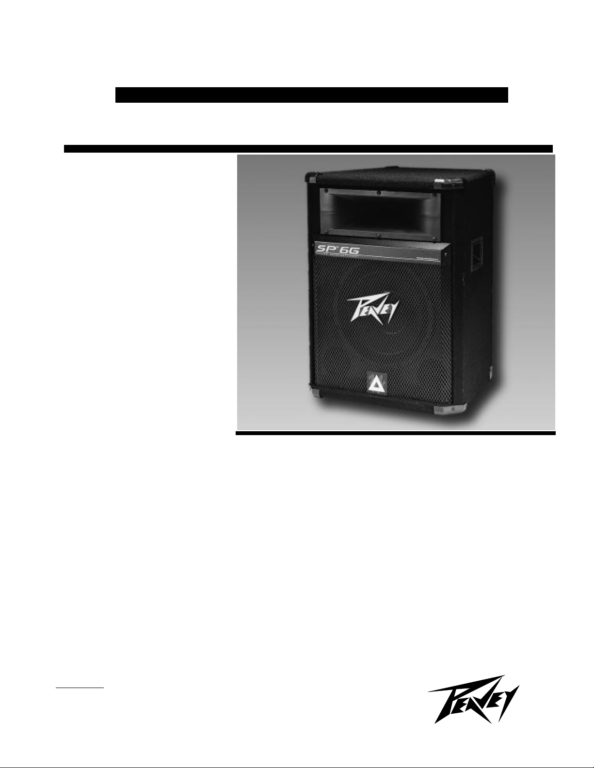
SP
Sound Reinforcement
Enclosure with
Sound Guard
Protection
SPECIFICATIONS
Frequency Response, 1 meter on-axis,
swept-sine in anechoic environment:
70 Hz - 15.0 kHz
Low-Frequency cutoff (-3 dB point):
70 Hz
6G
System
™
HF
Usable Low-Frequency limit (-10 dB
point):
55 Hz
Power Handling:
Full-Range:
200W continuous (40.0V RMS)
400W program
800W peak
Bi-amp Low:
200W continuous (40.0V RMS)
400W program
800W peak
Bi-amp High:
40W continuous (17.9V RMS)
80W program
160W peak
Sound Pressure Level, 1 watt, 1 meter
in anechoic environment:
Full-Range:
97 dB (2.8V)
Bi-amp Low:
96 dB (2.8V)
Bi-amp High:
104 dB (2.8V)
Maximum Sound Pressure Level (1
meter):
Full-Range:
117 dB continuous
122 dB peak
Bi-amp Low:
116 dB continuous 124 dB peak
Bi-amp High:
120 dB continuous 126 dB peak
Radiation Angle measured at -6 dB
point of polar response:
500 - 1,600 Hz:
Horizontal: 105
Vertical: 100o±-25
1.6 - 5 kHz:
Horizontal: 75
Vertical: 80o ±30
5 - 16 kHz:
Horizontal: 90
Vertical: 45o ±5
Directivity Factor, Q (Mean):
5.6 dB + 6.7 dB, -0.1 dB
Directivity Index, Di (Mean):
7.5 dB + 3.4 dB, -0.6 dB
Transducer Complement:
One heavy-duty, 12-inch
Sheffield
compression driver on a CH®-3
constant directivity horn.
®
woofer and one 22XT
o
o
±5
o
±10
±-20
o
o
Box Tuning Frequency:
58 Hz
Crossover Frequency (Internal
Passive):
1,640 Hz
o
o
o
o
™
Minimum Recommended Active
Crossover Frequency and Slope for
Bi-amping:
1,200 Hz at 18 dB/octave
Time Offset:
0.17 ms (delay Lows)
Impedance (Z):
Full-range nominal: 8Ω
Full-range minimum: 6.6Ω
Lows nominal: 8Ω
Highs nominal: 8Ω
®
Page 2
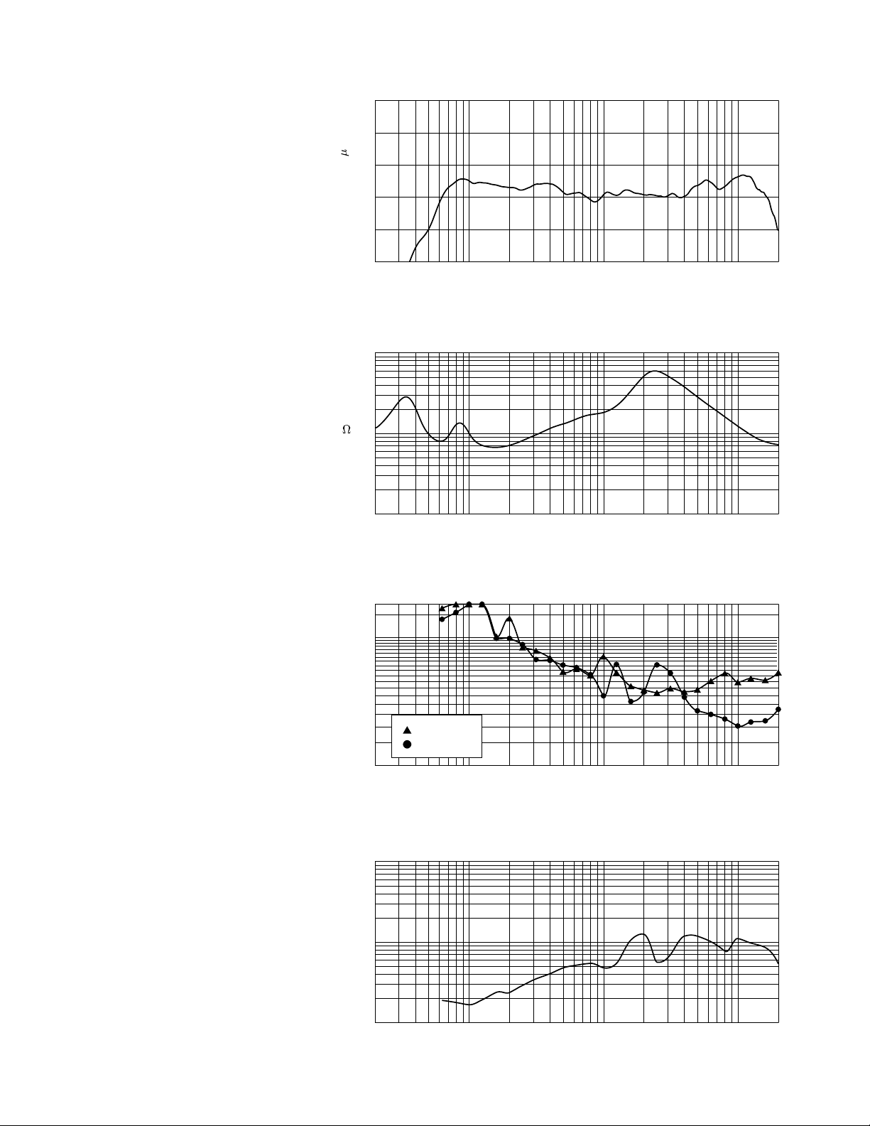
20 50 100 200 500 1k 2k 5k 10k 20k
Frequency (Hz)
30
40
60
80
100
140
180
300
360
Beamwidth (Degrees)
Beamwidth
Vertical
Horizontal
Figure 3
20 50 100 200 500 1k 2k 5k 10k 20k
Frequency (Hz)
70
80
90
100
110
120
dB SPL (re 20 Pa)
Amplitude Response (1W 1m On-Axis)
Figure 1
20 50 100 200 500 1k 2k 5k 10k 20k
Frequency (Hz)
1
10
100
Q & Directivity Index
Q
Figure 4
20
10
Di
0
20 50 100 200 500 1k 2k 5k 10k 20k
Frequency (Hz)
1
2
3
5
10
20
30
50
100
Impedance
Z
(
)
Figure 2
Input Connections:
2 x 1/4" phone jack (full range)
1 x 1/4" phone jack (bi-amp low)
1 x 1/4" phone jack (bi-amp high)
Enclosure Materials & Finish:
• 3/4" high-density particle
board enclosure covered with
black carpet and protective
polymer corners
• Expanded metal grille to
protect low-frequency driver
Mounting Provision:
One SA-1 stand mount on bottom
of enclosure.
Dimensions (H x W x D):
24.625" x 18.75" x 16.5"
(62.55 cm x 47.63 cm x 41.91 cm)
Net Weight:
62.1 lbs. (28.1 kg)
Shipping Weight:
71.8 lbs. (32.57 kg
)
Features:
• SH 12862 12" Sheffield
woofer
™
• 22XT
•CH
compression driver
®
-3 constant directivity horn
• Sound Guard
protection circuit
™
• SA-1
stand adaptor
™
high-frequency
®
Description:
The SP 6G is the result of redesigning the 112SE. They share the
same speaker complement, the 22XT
compression driver/CH-3 constant
directivity horn and the popular 12"
Sheffield woofer. However, changes
have been made to add to the performance and appearance of this unit.
Due to many requests, the SP 6G
features a new trapeziodal cabinet in a
very tight package. This shape greatly
reduces standing waves within the
cabinet and offers the ability to place
several SP 6G’s in an array. Each
cabinet is protected by polymer
corners and Peavey’s durable black
carpet as well as a powder-coated,
expanded metal grille.
This full-range enclosure provides
two parallel 1/4" inputs and both Hi
and Lo inputs for bi-amp use. The SP
6G crossover utilizes Peavey’s
proprietary high-frequency driver
protection circuitry, Sound Guard. The
input signal is routed through the
Sound Guard circuit in both full-range
and bi-amp modes of operation. When
the high-frequency drive level exceeds
a predetermined threshold, the Sound
Guard circuit is engaged
Page 3

Horizontal Polar Patterns 6 dB per Division
-90
o
-60
o
-30
o
0
o
30
o
60
o
90
o
-90
o
-60
o
-30
o
0
o
30
o
60
o
90
o
0
o
30
o
60
o
90
o
-30
o
-60
o
-90
o
0
o
30
o
60
o
90
o
-30
o
-60
o
-90
o
o
o
30
o
60
o
90
0
o
-30
o
-60
o
-90
o
90
o
30
o
60
500 Hz 2 kHz
o
o
30
o
60
o
90
0
o
-30
o
-60
o
-90
o
90
o
30
o
60
o
0
1 kHz
o
0
o
-30
o
-60
o
-90
o
-30
o
-60
o
-90
4 kHz 16 kHz8 kHz
Vertical Polar Patterns 6 dB per Division
o
90
o
-90
o
60
o
30
o
0
o
-30
o
-60
500 Hz 2 kHz
o
90
o
60
o
30
o
0
o
90
o
-90
1 kHz
o
90
o
60
o
30
o
0
o
-30
o
-60
o
60
o
30
o
0
o
-30
o
-60
-90
-60
o
o
-90
4 kHz 16 kHz8 kHz
o
-30
o
Page 4

automatically. This subtly decreases
the signal level going to the 22XT so
that it will not be damaged due to longterm overpowering. Short duration
transients will not be attenuated by
Sound Guard and have the possibility
to damage the 22XT. The Sound
Guard circuit is a dynamic circuit that
increases attenuation of the signal as it
increases in amplitude. This is accomplished throught the use of a specially
selected, dynamically resistive light
bulb. If the bulb in your Sound Guard
should ever burn out, a replacement
may be obtained from an Authorized
Peavey Service Center. However, if a
Peavey replacement bulb is not readily
available, an automotive type1156 bulb
may be substituted for temporary use
until a Peavey bulb can be obtained.
Frequency Response:
This measurement is useful in
determining how accurately a given
unit reproduces an input signal. The
frequency response of the SP 6G is
measured at a distance of 1 meter
using a 2.8 volt swept-sine input
signal. As shown in Figure 1, the
selected drivers in the SP 6G combine
to give a smooth frequency response
from 70 Hz to 15.0 kHz.
Directivity:
Beamwidth is derived from the -6
dB points from the polar plots (see
Figure 3) which are measured in a
whole space anechoic environment.
These are specifications which provide
a reference to the coverage characteristics of the unit. These parameters
provide insight for proper placement
and beamwidth and directivity (Figure
3 and 4) suitable for sound reinforcement applications.
Power Handling:
There are many different
approaches to power handling ratings.
Peavey Electronics rates this unit's
system power handling using a modified form of the AES Standard 2-1984,
utilizing audio band limited (20 Hz - 20
kHz) pink noise with peaks over four
times the RMS level. This strenuous
test signal assures the user that every
portion of this system can withstand
today's high-technology music. The
test signal contains large amounts of
very low- frequency energy, effectively
simulating the frequency content of live
music situations. The full measure of
high frequencies in the test signal
allow for exposure of the speaker
system to synthesized tones that may
extend beyond audibility. This rating is
contingent on having a minimum of
3 dB of amplifier headroom available
so as to ensure that clipping does not
occur.
Architectural and Engineering
Specifications:
The loudspeaker system shall
have an operating bandwidth of 70 Hz
to 15 kHz. The nominal output level
shall be 97 dB when measured at a
distance of one meter with an input of
one watt. The nominal impedance
shall be 8 ohms. The maximum
continuous power handling shall be
200 watts, maximum program power
of 400 watts and a peak power input of
at least 800 watts, with minimum
amplifier headroom of 3 dB. The
nominal radiation geometry shall be 90
degrees in the horizontal plane and 45
degrees in the vertical plane. The
outside dimensions shall be 24.625
inches high by 18.75 inches wide by
16.5 inches deep. The weight shall be
62.1 pounds. The loudspeaker system
shall be a Peavey model SP 6G.
ONE YEAR LIMITED WARRANTY
NOTE:
For details, refer to the warranty
statement. Copies of this statement
may be obtained by contacting Peavey
Electronics Corporation, P.O. Box
2898, Meridian, MS 39302-2898.
®
TM
Features and specifications subject to change without notice.
®
Peavey Electronics Corporation 711 A Street / Meridian, MS 39301 / U.S.A. / (601) 483-5365 / Fax 486-1278
©1997 Printed in U.S.A. 4/97
80300491
 Loading...