

Page 1
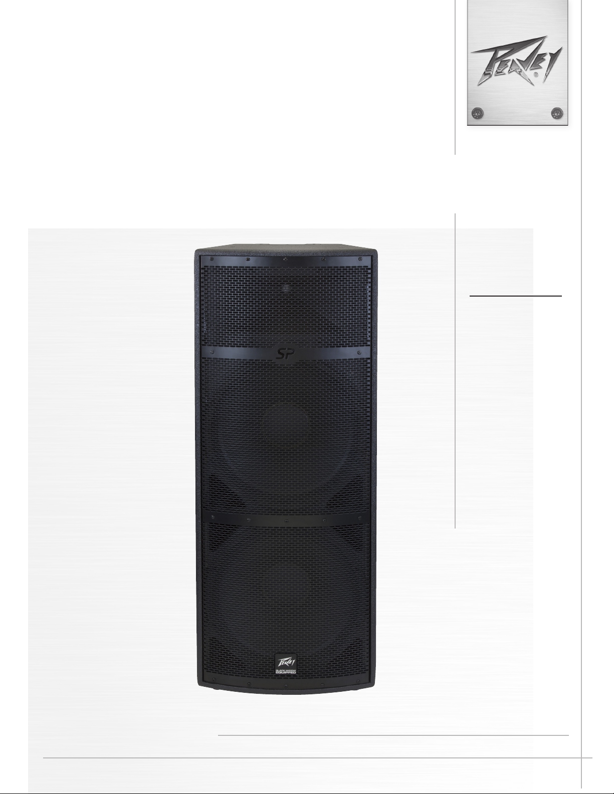
SP®4P
Powered Speaker System
Product
Specications
www.peavey.com
Page 2

FCC/ICES Compliancy Statement
This device complies with Part 15 of the FCC rules and Industry Canada license-exempt RSS Standard(s). Operation is
subject to the following two conditions: (1) this device may not cause harmful interference, and (2) this device must
accept any interference received, that may cause undesired operation.
Le présent appareil est conforme aux CNR d’lndustrie Canada applicables aux appareils radio exempts de
licence. L’exploitation est autorisée aux deux conditions suivantes: (1) I’appareil ne doit pas produire de
brouillage, et (2) I’utilisateur de I’appareil doit accepter tout brouillage radioélectrique subi, même si le
brouillage est susceptible d’en compromettre le fonctionnement.
Warning: Changes or modifications to the equipment not approved by Peavey Electronics Corp. can void the
user’s authority to use the equipment.
Note – This equipment has been tested and found to comply with the limits for a Class B digital device,
pursuant to Part 15 of the FCC Rules. These limits are designed to provide reasonable protection against
harmful interference in a residential installation. This equipment generates, uses, and can radiate radio
frequency energy and, if not installed and used in accordance with the instructions, may cause harmful
interference to radio communications. However, there is no guarantee that interference will not occur in a
particular installation. If this equipment does cause harmful interference to radio or television reception,
which can be determined by turning the equipment off and on, the user is encouraged to try and correct the
interference by one or more of the following measures.
• Reorient or relocate the receiving antenna.
• Increase the separation between the equipment and receiver.
• Connect the equipment into an outlet on a circuit different from that to which the receiver is
connected.
• Consult the dealer or an experienced radio/TV technician for help.
Caution
The equipment complies with FCC radiation exposure limits set forth for an uncontrolled
environment.
Page 3

ENGLISH
SP®4P
e Peavey® SP®4P is a powered, bi-amplied, two-way speaker system engineered to provide very high levels of
performance in a compact powered loudspeaker. is quasi-three-way powered system is comprised of a 1000
W peak switching power amplier driving a pair of 15” Black Widow® BWX series woofers, now with a long
throw voice coil. e 2” RX™22CT titanium diaphragm compression driver is driven by a 500 W peak switching
power amplier, and is coupled to a low coloration waveguide with a coverage pattern of 100° horizontal by 50°
vertical.
e SP®4P is capable of up to 131 dB peak SPL. e enclosure is constructed of plywood augmented with internal
braces, covered with a textured black painted nish. e shape is a trapezoidal form, with a full-length coated
perforated steel grille, to oer an attractive yet durable powered speaker system. A pair of four-way inset handles,
one on each side, and a set of casters on the bottom rear edge and a top rear handle provide convenient transport
and handling. Multiple y points are provided to allow overhead rigging. e cabinet and grille are black.
Two independent mixed input channels each oer a balanced input to the preamp/EQ electronics, and a level
control. Each channel has one combo female XLR and 1/4” TRS phone jack. It is switchable between mic-level
and line-level sensitivity. Channel 2 has a 3.5 mm media jack added. A line out section has male XLR connectors. e ru outputs allow linking of additional speaker systems, or feed of the signal to a powered subwoofer,
etc.
e power ampliers providing the bi-amplication are low-distortion switching units providing 1000 W peak
available power into the nominal 4 ohm load of the woofer, and a 500 W peak available power into the nominal 8
ohm load of the tweeter. e power supply for both amps is a switch mode type for low weight and high eciency. Both ampliers feature our DDT™ compression, which virtually eliminates audible power amplier clipping.
Cooling is via forced air circulation.
e combination of the Black Widow® BWX woofer with the RX™22CT tweeter and DSP crossover and EQ provide a clarity and impact beyond conventional powered enclosures. e switching power amps and switch-mode
power supply, along with the professional grade speaker components, provide this high level of technological
sophistication at a very light weight, while at a very reasonable cost.
* BI-AMPLIFIED POWERED SPEAKER SYSTEM
* 1000 WATTS PEAK AVAILABLE WOOFER POWER, 500 WATTS PEAK AVAILABLE TWEETER POWER
* BOTH POWER AMPS HAVE DDT COMPRESSION
* TWO 15” BLACK WIDOW® BWX WOOFERS
* PEAVEY RX™22CT COMPRESSION DRIVER TWEETER ON A QUADRATIC THROAT WAVEGUIDE
* PEAK SPL UP TO 131 DB WITH MUSIC!
* DSP BASED CROSSOVER, LIMITING AND EQ
* EQ PRESETS AVAILABLE VIA ROTARY ENCODER PUSHBUTTON SELECT
* 9-BAND EQ AND OTHER SYSTEM SETTINGS ACCESSED VIA ROTARY ENCODER PUSHBUTTON SELECT
* DYNAMIC BASS BOOST FUNCTION
* UP TO 150 MS OF ARCHITECTURAL DELAY
* FAN COOLED FOR MAXIMUM RELIABILITY
* TWO INDEPENDENT MIXED INPUT CHANNELS, WITH GAIN CONTROL AND MIC/LINE GAIN SWITCH
Page 4
* EACH CHANNEL FEATURES A COMBO JACK WITH 1/4” TRS & FEMALE XLR BALANCED INPUT
* INPUT 2 HAS A 3.5 MM (1/8”) STEREO MEDIA INPUT JACK
* OUTPUT CONNECTORS ARE MALE XLR
* FOUR-WAY INSET HANDLES ON EACH SIDE
* TILT-BACK CASTERS AND TOP REAR BACK HANDLE
* FULL LENGTH PERFORATED STEEL GRILLE
* RUGGED PLYWOOD ENCLOSURE, WITH BRACING AND DADO CONSTRUCTION
* REDUCED WEIGHT – ONLY 93 POUNDS!
* MULTIPLE FLY POINTS
Applications
The Peavey® SP®4P has a variety of applications such as sound reinforcement, public address, side fill system,
karaoke or musical playback.
A typical signal source for the line-level inputs of the Peavey SP®4P would be a sound reinforcement mixing
console (mixer) or the output from a CD player, MP3 player or tape deck. A dynamic microphone can be
connected directly and used as well.
Bottom Rear Panel
Page 5

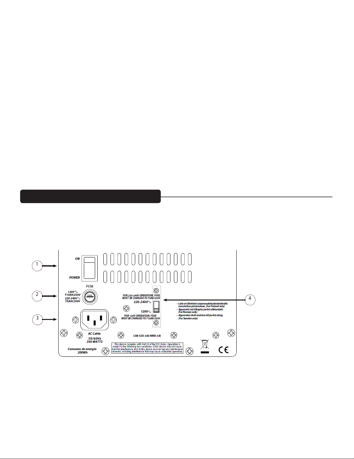
ON-OFF SWITCH (1)
This rocker switch supplies AC power to the SP®4P when switched to the ON position. The ON position is with
the top side of the switch pushed “in” or nearly flush with the rear panel.
FUSE (2)
The unit is AC power line fuse protected from overloads and fault conditions with a slow-blow 5 x 20mm
250V fuse. This fuse is located within the cap of the fuse holder. If the fuse fails, THE FUSE MUST
BE REPLACED WITH THE SAME TYPE AND VALUE IN ORDER TO AVOID DAMAGE TO THE
EQUIPMENT AND TO PREVENT VOIDING THE WARRANTY!
The fuse in the SP®4P can be replaced with a time-delay type 5 x 20 mm size 250V rated fuse.
For 120VAC operation, a fuse rated at 10 amps should be used. In the USA, types GDC, GMC, 215, 218, and
477 cartridge-style 5 x 20 mm size fuses with a 10 amp 250V rating can be used.
For 220-240VAC operation, a fuse rated at 5 amps and 250V should be used, which conforms to the
international fuse classification “T5AH”.
If the unit continues to blow replacement fuses, do not keep replacing them, it should be taken to a qualified
service center for repair.
To replace the fuse, be sure to remove the IEC power cord from the IEC socket.
IEC POWER CORD CONNECTION (3)
This receptacle is for the IEC line cord (supplied) that provides AC power to the unit. It is very important
that you ensure the SP®4P has the proper AC line voltage supplied. You can set the proper voltage for your
SP®4P using the Voltage Selector switch (4) on the rear panel of the unit.
Please read this guide carefully to ensure your personal safety as well as the safety of your equipment.
Never break off the ground pin on any equipment. It is provided for your safety. If the outlet used
does not have a ground pin, a suitable grounding adapter should be used and the third wire should be
grounded properly. To prevent the risk of shock or fire hazard, always be sure that the mixer and all other
associated equipment are properly grounded.
VOLTAGE SELECTOR SWITCH (4)
The SP®4P has a voltage selector switch to allow switching between an input power voltage of 120VAC
to a range from 220VAC to 240VAC, all at either 50 or 60 cycles per second (Hz). It should be set to the
proper voltage for your country out of the box. However, world conditions are such that some areas have
power line voltages differing from the voltage used by the majority of any given locale.
Be sure to check the position of the voltage selector switch to see that it matches the power line voltage used
locally. If it does not match, then to change the voltage to the correct one, follow the steps outlined on the next
page.
Page 6
Changing the Voltage Range of the SP®4P
First, make sure the SP®4P is disconnected from the power line, and that the power switch (1) is in the OFF
position.
Second, unscrew the screws holding the clear switch protector on the voltage selector switch (4) just a little, just
enough to allow rotation of the clear switch protector. The screws DO NOT need to be unscrewed very far.
Third, rotate the clear plastic protector about 90 degrees to uncover the voltage selector switch. One side of the
cover has a slot, the other just a hole, the side with the hole is the side that pivots.
Fourth, using a small at blade screwdriver, push the red selector switch slide plate to the other side from where
it was. The voltage that is now visible on the red slide plate is the one you have selected.
Fifth, rotate the clear plastic protector back underneath the loosened screws, and tighten one down while
holding the clear plastic protector in place. Tighten the other screw down, and make sure both screws are tight.
If the screws are over-tightened, this could damage the voltage selector switch clear plastic cover, so do not
apply excessive force to the screws!
Sixth, the fuse should be changed to the correct amperage rating. For an input power voltage of 120VAC,
use a 10 amp rated, 250V 5 x 20 mm cartridge type time-delay fuse, which conforms to the international fuse
classication “T10AH”.
For an input power voltage range of from 220VAC to 240VAC, use a 5 amp rated, 250V 5 x 20 mm cartridge
type time-delay fuse, which conforms to the international fuse classication “T5AH”.
The IEC power cord that is correct for your locale can now be plugged into the IEC receptacle (3), and the
Power switch (1) activated to turn on the powered SP®4P speaker system.
Top Rear Panel
Page 7

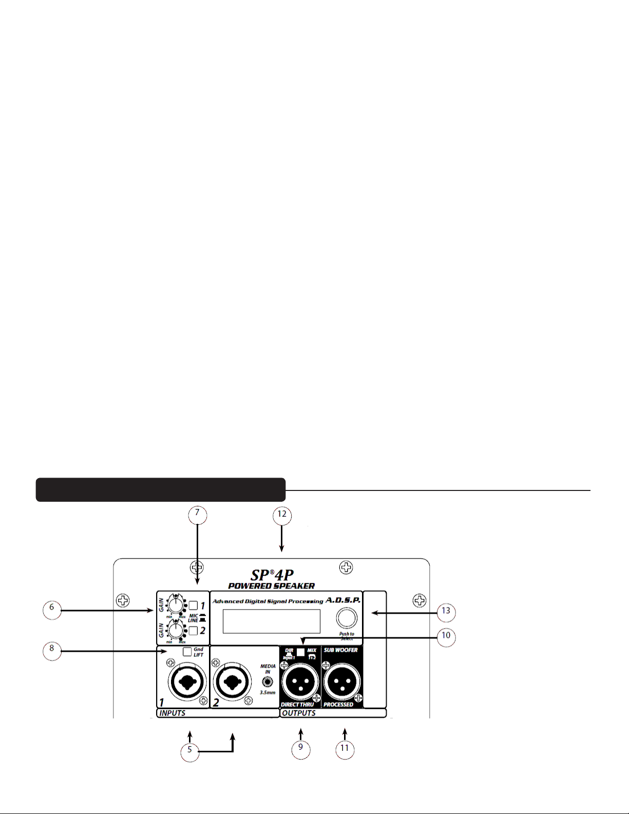
INPUTS (5)
Two input channels are provided. e line-level input is of the medium impedance balanced type. e jack is a
combo female XLR and 1/4” TRS connector. Sensitivity of this input is 0.42 volts for full output, when the MIC/
LINE switch (7) is in the LINE position.
Channel 2 has a 3.5 mm input jack for mobile device signal sources.
GAIN CONTROLS (6), Present on both input Ch 1 and input Ch 2
Controls the gain or output level of the same numbered input channel. It is used to directly set the system output
level for a given input signal.
MIC/LINE switch (7), Present on both input Ch 1 and input Ch 2
Switches between LINE level gain (out position) and MIC level gain (in position). MIC position increases gain
26 dB to allow use of most dynamic microphones.
NOTE: Phantom power is not supplied on the INPUT (5) jacks
Gnd LIFT switch (8)
Allows the shield to be disconnected from the chassis ground to alleviate hum from ground loops
DIRECT THRU output jack (9)
is jack is intended for the use of linking multiple SP®4P’s in a line,
or to provide a feed to a powered subwoofer, or other electronics that needs to receive a full range version of the
input signal.
DIR/MIX switch (10)
Switches between Direct ru from channel 1 input, or a mix of channel 1 and channel 2 at the Direct ru output (9)
SUB WOOFER PROCESSED output jack (11)
Provides a ltered signal for use with powered Sub woofer speaker systems other than the SP®118P or SP®218P.
Follow the instructions in the Setup Wizard in the SP®4P menu on the LCD screen using the Push-To-Select
button for proper subwoofer set-up and connection.
LCD Display (12)
Provides a menu read-out manipulated and activated by the Push-To-Select button (13)
Push-To-Select button (13)
Rotary knob that allow the user to select and choose menu options on the LCD display screen (12). Pushing the
button in till it detents makes a menu choice, selecting the action or option highlighted in the LCD screen.
Page 8

Safety Information
Cautions
e unit must be disconnected from the AC power source before any work is done on it. Refer all servicing to
qualied service personnel.
e back plate can become hot to the touch. Do not block or cover the fan or the exhaust louvers from
ventilation. ere must be a minimum of 4” of space behind the fan. Do not allow the airow to be become
blocked by objects such as curtains or drapes, thermal building insulation, etc. It is recommended that the rear
of the SP®4P not be placed in a closed space or a space that has no fresh, cool airow.
Be sure to keep the microphone away from the front of the speaker aer connecting it to the input, and while
setting the microphone level, or very loud feedback will occur! Damage to the system is likely if this occurs!
DO NOT connect the inputs of the SP®4P to the output of a power amplier. e inputs are meant to be driven
from a line-level strength signal.
DO NOT remove the protective metal grille.
WARNING! e SP®4P is very ecient and powerful! is sound system can permanently damage hearing! Use
extreme care setting the overall maximum loudness!
e apparent sound level of the SP®4P can be deceiving due to its clear, clean sound output. e lack of distortion
or obvious distress can make the sound level seem much lower than it actually is. is system is capable of SPL in
excess of 131 dB at 1 M from the speaker!
Flying/Rigging Information
Caution: Before attempting to suspend this speaker, consult a certied structural engineer. Speaker can
fall from improper suspension, resulting in serious injury and property damage. Do not suspend or mount
any other product or device from this enclosure! Maximum enclosure angle 30°. Use only the correct mating hardware. All associated rigging is the responsibility of others.
Whenever possible, in addition to the nominal primary mounting method, use a suitable safety chain or wire
rope, attached to one of the other groups of inserts, and rmly attached to a suitable structural member as indicated by a certied structural engineer.
We recommend the use of read-locker at the insert point bolts, so the bolts cannot vibrate loose.
Never transport the cabinet using the array bracket or other mounting brackets as a structural member, while
the cabinet is mounted on an array bracket or other mounting bracket and unsupported otherwise, as this may
unduly stress the mounting inserts.
is Peavey loudspeaker should be suspended overhead only in accordance with the procedures and limita-
tions specied in the User’s Manual and possible manual update notices. is system should be suspended
with certied rigging hardware by an authorized rigging professional and in compliance with local, state and
federal suspension ordinances.
WARNING! (note to structural engineer)
NOTE: Use the correct type and grade of bolt into the mounting point inserts. e correct mounting bolt
diameter and thread spacing are: M8, 1.25 mm per thread. Use of a metric grade 8.8 bolt or better is recom-
Page 9

Hardware for Flying/Rigging the SP®4P
Eyebolts or bracket bolts should be M8 metric thread, 1.25 mm per thread.
Eyebolts and bracket bolts must conform to certain minimum strength criteria for safety reasons.
Unspecied eyebolts found at local hardware stores are not strong enough to maintain safety for overhead ying
or rigging. Use only forged steel shoulder machinery eyebolts designed for rigging use, which adhere to the stated standards as outlined below.
Hardware Specications
Forged shoulder machinery eyebolts should be an M8 size, 1.25 mm per thread, and must conform to DIN 580
or ASTM A489, for Germany, BGV-C1 is the relevant standard. Minimum shank length should be 20 mm. e
eyebolts should be rated for a minimum of 450 lbs straight pull working load
Bolts used on custom mounting brackets must be certied to be a metric grade 8.8 or better.
If there are any questions regarding the proper hardware or practices for safe ying or rigging of the Peavey
SP®4P, contact a certied structural engineer, or consult with those local rigging companies who have trained
and certied personnel.
Operation
Connecting AC Power To e SP®4P
When installing the SP®4P, AC power runs will be used and a certied electrician should be consulted to be
sure that all AC wiring complies with local codes and regulations. It is also advisable to use a cable clip properly
axed to the cabinet to strain relief the IEC power cord connected to the amplier module at (3) so the power
cord cannot be pulled out or vibrate loose.
Special Note for Permanent Installation
When installing the SP®4P, AC power runs will be used and a certied electrician should be consulted to be
sure that all AC wiring complies with local codes and regulations. It is also advisable to use a cable clip properly
axed to the cabinet to strain relief the IEC power cord connected to the amplier module at (3) so the power
cord cannot be pulled out or vibrate loose.
Use of the SP®4P on a Stage or on top of a Subwoofer
Always place the SP®4P on a at, level and stable surface, and be sure to secure the Sub so it can not roll or fall
o of the stage or sub. e SP®118P Sub or SP®218P Sub can be used with an SP®4P using the electrical crossover
supplied with the Sub.
Page 10

Connecting a Signal to the SP™4P
ere are a variety of ways to input a signal to the SP®4P.
e inputs (5) provides either a balanced mic- or line-level input, allowing the use of a 1/4” TRS (ring-tip-sleeve)
type phone plug or a male XLR plug.
ere is also a 3.5 mm MEDIA IN jack on the Channel 2 input.
e 3.5mm TRS input jack has its own preamp designed for connection to the headphone jack on mobile audio
devices. e Channel 2 Gain control adjusts the signal level from all of the channel 2 input connectors. It is possible to use both the combo mic or line input and the 3.5mm input by setting the channel 2 Gain control for the
combo input source, and then using the mobile devices headphone volume to adjust its volume.
Note that the 3.5 mm jack mixes a stereo signal down to monophonic, as the SP®4P is a single sound source.
Do not connect cables to the jacks while the unit is ON and the Gain knob is turned up! While a standard
single-ended 1/4” phone plug-equipped cable will work well and the balanced input circuitry will provide some
interference rejection, a balanced cable using either the balanced TRS 1/4” phone plug or the XLR plug will provide superior interference rejection and performance.
Sometimes, with dicult interference problems, it will be helpful to li the shield ground ( Pin #1 of an XLR)
of a balanced cable at the SP®4P end. Check any input changes carefully, always turning the Gain control down
before plugging and unplugging cables, or liing the ground.
Use of high quality, premium cables is recommended for the SP®4P, as these usually have better shielding and
materials and will provide greater long-term reliability. e best option is a shielded balanced cable no longer
than necessary to reach the SP®4P. It is usually a good idea to leave some slack at the input to the SP®4P and
also to tape the cables down or run them under a cable guard to avoid anyone tripping over them or pulling the
SP®4P over when stand mounted.
Gain Control Adjustment
e SP®4P is equipped with Gain controls (6) on the input to facilitate use in many dierent applications. With
the Gain control adjusted fully clockwise, gain is at maximum and the input sensitivity is 0.42 V RMS for
full-rated output with the line level position of the Mic/Line switch (7). When driving the SP®4P from a mixer, it
may be advantageous to reduce the input sensitivity by turning the Gain control to the halfway point. e SP®4P
will now more closely match a typical power amp.
If the mixing board indicates clipping of its output signals, then all of the SP®4P power capability is not being
utilized cleanly. Clipping the signal before it gets to the SP®4P is not optimal. Reduce the mixer
output level and turn up the Gain control/s on the SP®4P.
e ampliers in the SP®4P are equipped with DDT™ and there is an indication on the rear panel LCD display
(12) that reads “DDT” whenever the DDT system engages.
If the sound seems heavily compressed, check this indicator; if it is blinking more than occasionally, then the
drive level from the mixer (or the Gain control on the SP™4P) needs to be reduced.
When rst turning on the sound system, switch on all upstream electronics rst, then the SP®4P with its Gain
control fully counterclockwise (all the way down). Begin checking levels with the mixer output level controls all
the way down, and bring them up slowly with the SP®4P Gain control/s set to the desired setting (one-third way
up recommended to start).
It is not good practice to turn the Gain control/s on the SP®4P all the way up and then try to control level only
Page 11

from the mixer, this approach would tend to pick up excess noise. Best practice would be to run a “hot” signal
from the mixer down the cable to the SP®4P, and then turn the SP®4P Gain control up only as much as necessary
to reach full desired output. With this approach, it is necessary to verify the mixer output is not clipping.
Disconnecting AC Power to the SP™4P
We recommend that the Power switch (1) be used to turn the unit o rst, and then the AC power cord can be
removed, this minimizes stress to the power ampliers and the transducers from turn-o transients. e power
switch has an arc suppression capacitor to help during turn-o, and tends to make a clean disconnect from the
AC power, while the power cord IEC connector can make intermittent contact before nally becoming fully
disconnected, e.g., as when wiggling the cord.
Page 12

DSP User Control Menu Operation
A two-line, 16-character per line LCD and a rotary push-to-select encoder make up the interface for this product.
e DSP processing control accessible by the user, consists of a 9-band graphic equalizer (GEQ), choice of output
Polarity, selection of Bass Enhancement, and signal Delay. is is applied to the powered speaker system, and in
some cases, to the processed output. e user can also select from a menu of preset Program EQ settings that are
applied to the graphic equalizer and Bass Enhancer.
User interface:
Rotating the encoder takes the user thru the top level menu screens. ese screens will display current information such as a Input Level meter, conguration and current user settings. Pressing the encoder on a top level
screen will take the user to related selection screen(s) when relevant. e conguration screens play an important role in preparing the speakers for the intended application. e conguration screen comes up aer the
initialization screen when the speaker is powered on. If the conguration screen is not selected within 5 minutes
the Input Level screen is displayed . e user can still select this screen at any time by rotating the edit knob.
e conguration screens help the user set up the SP®4P system for optimal operation. By answering a couple of
questions, the processor is congured and proper connections displayed. When complete, the user is returned to
the main menu.
e LCD backlight will dim aer 5-minutes without interface activity but returns to full brightness when the
encoder is moved. When the backlight auto-dims, the display returns to the Input Level screen. is prevents
inadvertent changes from occurring while reactivating the LCD backlight.
e main menu screens are:
Congure?
Input Level
Program EQ (Presets)
Bass Enhancement
Delay
Graphic EQ
Polarity
Power amp meters Low and High
Power amp Temperature
Front LED On/O
Auto power O
Security Lock
Main Screens:
Input Level meter: Displays current input signal level.
Will prominently display status if DDT is engaged, by displaying the letters “DDT” on the right hand side of the
displ ay.
Congure?
Push Select is is an overview display that is not directly edited.
Entering the conguration menu directs the user how to properly set up and connect the system.
Page 13

First Screen displayed aer pushing Congure?
Use Speaker with
Subwoofer? Yes or No
If subwoofer = No: then go to location screen
No is the default selection.
If subwoofer = Yes then: Subwoofer selection screen
Subwoofer used:
Selections
SP Subwoofer
Other Sub 100 Hz
Other Sub 110 Hz
Other Sub 120 Hz
NOTE: e rotary knob must be used to scroll down to see all the choices.
If SP Subwoofer
Connect Mixer to
Sub Input
Connect Sub Proc
Out to Input
Speaker Proc Out
is Muted
With the mixer output (sound source) connected to the subwoofer, all of the system adjustments will be made
using the SP Sub DSP module. e User processing choices in the SP®4P, such as the 9 band GEQ, will be bypassed, the delay will be bypassed, and the processed output muted. Program EQ (presets), GEQ and delay
screens are all aected. e hi-pass lter on the SP®4P woofer is unchanged from it’s full range setting, because
the Sub performs the crossover functions.
If Other Subwoofer
Connect Mixer to
Speaker Input
Connect Proc
Out to Sub Input
When the Sub is selected, the program EQ (presets), GEQ and delay screens function normally. e Processed
output sends a subwoofer signal out the processed output. e Hi-pass lter on the SP®4P woofer is raised to
cross-over with the subwoofer processed output at the selected frequency.
Page 14

Program EQ: Displays current EQ selection (EDM preset is the default on 1st time power up)
(Presets) EDM, Voice, Rock, DJ...etc
e program EQ selection is applied to the Graphic Equalizer and Bass enhancer.
“Custom” is displayed if GEQ has been adjusted by the user.
e last preset used, including a Custom one, is what will load the next time the SP®4P is powered
up.
Note: If input source is from the SP Sub High-Pass Processed output, then the screen will display:
“EQ Bypassed”
“Use EQ in SP Sub”
Bass enhancement: O or On.
Delay: Current delay time
Adjust screen 0 to 150 msec also Feet and Meters
Note: In SP®4P if input source is SP® Sub, then Display:
“Delay Bypassed”
“Set DLY in Sub”
Graphic EQ: Current settings 9 Bands +/- 12 dB at ISO octave centers (63Hz to 16 kHz)
Note: In SP®2P if input source is SP Sub, then Display:
“EQ Bypassed”
“Use EQ in SP Sub”
Press the encoder to enter the screen to adjust the GEQ. Turning the encoder selects the frequency band to be
adjusted. Press the encoder to adjust that band. Pressing the encoder again returns to the band select mode. To
exit to the main menu, turn the encoder past the 16 kHz band to the X and Exit will appear. Press the encoder to
exit.
Speaker Polarity:
Normal (Default Selection)
Inverted
Power amp Level meter display:
e input signal to the two power ampliers will be displayed in horizontal VU format. e Limit status of
each channel is also displayed.
Temperature: e temperature of the amplier is monitored and display as long as it is in a safe operating range.
If the temperature gets too high, it goes into protect mode which is displayed here and on the main Input Level
screen.
Front LED: Set LED operation to: On/DDT, Signal/DDT, or O.
When On/DDT indication is selected, the LED is lit blue whenever the ampliers are not shut
down.
When Signal/DDT indication is selected, the LED is lit blue whenever there is an input signal
present.
When O indication is selected, the LED is not lit under any conditions.
Auto power o: Disable, 15, 30 or 60 minute delay.
Page 15

Security Lock: A four digit security lock that can be engaged that will block editing of all parameters. If locked,
entry of the access code will be required to allow temporary access for editing. It will automatically relock aer 5
minutes of editing inactivity.
Troubleshooting
No Output at All
First, make sure the unit has AC power and is turned ON. Make sure the LCD on the power amp module is
illuminated.
If not, make certain the ON/OFF switch (1) is in the ON position and check the IEC power cord connection (3)
by ensuring it is fully engaged and seated. Make certain the AC line cord is plugged into a working AC outlet.
Finally, check the fuse (2). (See the Rear Panel: FUSE section, for safety instructions.)
Once assured your unit is getting AC power, check that the SP®4P is getting a signal. Temporarily disconnect the
cable running to its inputs and connect it to some other device capable of reproducing the signal (i.e., a power
amp and speaker). If this produces a signal, make sure that all Level controls being used have been turned up to a
satisfactory level (one-third to halfway).
If the SP®4P has been subjected to direct sunlight or excessive heat, the built-in thermal protection may have
been triggered. If so, turn o the SP®4P and let it cool for a sucient amount of time.
If there is still no output, contact your authorized Peavey dealer or the Peavey International Service Center.
Hum or Buzz
If the SP®4P is producing a hum or buzz, this can be AC outlet related. Try plugging the SP®4P into a dierent
AC outlet. Sometimes, if a dierent
circuit (breaker) is used for the mixer and for the SP®4P, it can cause hum problems. Unless it is not practical, it
is best to use the same wall outlet (breaker) to supply power to both the mixer and the powered speaker.
Ensure that shielded cables have been used to route the signal to the SP®4P input. If speaker cables with 1/4”
plugs are used as input cables instead of shielded cables, they will be prone to hum or buzz.
Hum may be ground loop related. It may be helpful to li the shield ground (Pin #1) on a balanced cable at the
SP®4P end. Check any input changes carefully by rst turning down the Level control, before plugging and unplugging cables, or liing the shield ground at the speaker end.
Check to make sure light dimmers are not on the same circuit as the SP®4P, the mixer or any source devices. If
light dimmers are used, then it may be necessary to turn them full ON or full OFF to eliminate or reduce hum.
is is a typical AC wiring/light dimmer interference problem, not a design aw of the SP®4P.
e third wire (ground plug) on the AC plug should NEVER be removed or broken o, as this is a potential
safety hazard.
Page 16

Distorted or Fuzzy Sound
First, ensure the mixer (signal source) is not clipping or being overdriven. Make sure the Gain (6) control on the
SP®4P has not been set too low. Check that the input plug is fully seated in the input jack on the rear panel of the
SP®4P. Ensure that a power amp has not been plugged into the input jack of the SP®4P. If an extension cord
is being used to provide the AC power to the unit, insure that it is of sucient current capacity and that it is not
also being used to supply power to any other device.
e SP®4P has built-in EQ to smooth and extend the natural response of the speakers. If excessive additional
bass boost or HF boost have been added externally to the SP®4P, it could cause premature overload at high SPL.
Reduce the amount of any external (mixer, rack) EQ and see if that clears up the distortion.
If no external bass boost or HF boost has been added, but there seems to be an excessive amount of bass boost
(boominess, bass clipping, and/or treble boost (shrillness, sizzle, harshness), then you may have selected the
wrong choice on the Set-Up Wizard in the DSP menu on the LCD display. Go back and select the proper choice.
If using the SP Sub as the main input from the mixer, and then running a cable from the Sub to the SP®4P , then
the SP®4P should be set to USE WITH SP SUB on the Set-Up Wizard menu.
If the Set-Up Wizard menu choice seems to be correct, and there is still too much boost, then try a preset with
less boost, such as the Acoustic (Flat) preset and make sure the Tone controls have not been set all the way up.
Finally, realize that even though the SP®4P is a powerful and high output unit, it does ultimately have limits, and
it may need additional powered units (or a subwoofer) to provide enough sound output or coverage. In this case,
try turning the mixer levels down a little to see if that clears things up. If, aer checking all the things listed to
check and anything else you can think of to check safely, and the system still exhibits problems, carefully note all
conditions and check with your Peavey dealer for advice.
Care and Maintenance
Your SP®4P is a sturdy and durable product and will provide years of reliable use if properly cared for. Use common sense and read the safety warnings to avoid hazardous operating conditions.
e unit must be disconnected from the AC power source before any work is done on it. Refer all servicing to
qualied service personnel.
Sunlight/Heat
Avoid prolonged exposure to direct sunlight, as this may cause the unit to overheat and thermally shut o.
Excessively hot operating conditions can also cause a thermal shutdown.
Do not store in extremely hot or cold conditions or extremely high humidity. Always allow unit to come to room
temperature before use.
Cleaning
Never clean the SP®4P while plugged in or turned ON! When the unit has been fully disconnected from AC
power sources, use a dry cloth to remove soil or other dirt. Never use strong solvents on the SP®4P, as they could
damage the cabinet. Do not allow ANY uids to drip inside the SP®4P.
Touch-Up
To touch up the painted surfaces of the SP®4P, you can use Peavey® Black Touch-Up paint (part # 00052110).
Never paint the enclosure or other parts while the unit is plugged in or turned on!
Page 17

Check for Secure Hardware
Aer the rst few weeks of use and periodically thereaer, check the hardware of the SP®4P for tightness, including the rear panel screws and the screws that hold the bae and rear cabinet together.
e unit is subject to a great deal of vibration, and this could cause the hardware to loosen with use.
Architectural and Engineering Specications
e powered loudspeaker system shall have a frequency response from 57 Hz to 17 kHz. e peak SPL with
inaudible distortion shall reach 131 dB with music as a source, when measured at a distance of 1M and driven to
full output capacity. e system shall utilize two Peavey® 15” Black Widow® woofers in a vented enclosure, and
a RX22CT compression driver tweeter mounted on an asymmetrical Quadratic roat CD horn . e nominal
radiation pattern shall be 100° in the horizontal plane, and 50° in the vertical plane, with the vertical main polar
lobe angled down 10 degrees with respect to straight ahead, the vertical coverage angles being +15. –35 deg.
e powered, bi-amplied loudspeaker system shall have two mixed input channels consisting of a medium
impedance input connector consisting of one combo female XLR and 1/4” TRS phone jack on the rear panel.
Channel two shall have a 3.5 mm input jack as well.
ere shall be a Direct ru (output) connector consisting of a male XLR jack.
e output of this jack shall be switchable between just Ch. 1 input and a Mix of Ch 1 and Ch 2.
e system power ampliers shall have an unltered frequency response of 20 Hz to 20 kHz which deviates no
more than +1, -3 dB up to rated power, hum and noise better than 90 dB below rated power, and THD and IMD
typically of less than 0.1%.
e woofer amplier shall be capable of 500W continuous into a 4 ohm nominal load, and the tweeter amplier
shall be capable of 250 W continuous output into a 8 ohm load, and both shall incorporate independent signal
compression.
e input signal shall be electronically divided into high frequencies and low frequencies by a Linkwitz-Riley
fourth order slope line-level crossover at 1.8 kHz. e low frequencies shall be processed to provide bass boost,
subsonic ltering and overall response shaping, and the high frequencies shall be equalized for response-shaping.
e enclosure shall be constructed of 15 mm plywood. Four-way inset handles shall be incorporated on each
side. A full-length powder-coated metal grille shall be provided for horn and woofer protection. e cabinet
shall incorporate four tall sturdy rubber feet for oor standing use.
e outside dimensions shall be: 43.50” (110.5 cm) tall x 16.75” (42.6 cm) wide x 16.85” (42.8 cm) deep, and the
weight shall be 93 lbs. Power requirements shall be: 200 Watts nominal, 120 VAC, 50/60 Hz Domestic and 220240 VAC, 50/60 Hz (Export). e loudspeaker system shall be called a Peavey® SP®4P.
Page 18

Product Specifications
SPECIFICATIONS
Enclosure: Peavey® SP™4P
Frequency response: 57 Hz to 17 kHz
Low frequency limit (-3 dB point): 57 Hz
Usable low frequency limit (-10 dB point): 50 Hz
Internal power ampliers (@120 VAC line):
Woofer - 1000 watts peak available power
Continuous Power: 500 watts @ less than 1% distortion
Tweeter - 500 watts peak available power
Continuous Power: 250 watts @ less than 1% distortion.
Nominal sensitivity (1W @1M, swept
sine input in anechoic environment): 100 dB (average)
Maximum sound pressure level: 131 dB music peak
Nominal radiation angles: 100° horizontal by 50° vertical
e vertical main polar lobe is angled down 10 degrees with respect to straight ahead, the vertical coverage angles being +15. –35 deg.
Transducer complement:
Low Frequency Section: 2 X 15” woofer, vented Black Widow® 1508-8 SPS
High Frequency Section: 1 X 1.0” exit, 50 mm voice coil RX22CT compression driver on asymmetrical
Quadratic roat CD Horn.
Box tuning frequency (Fbox): 65 Hz
Electroacoustic crossover frequency: 1.82 kHz
Crossover Slopes: 24 dB/octave (fourth order) low pass, 24dB/octave (fourth order) high pass, and driver EQ.
Input Connections: Two combo female XLR/ 1/4” phone jack providing balanced or unbalanced operation, and
one 3.5 mm stereo media jack.
Output Connections: Two XLR Outputs, one Full Range ru, electrically buered with selectable option of
Channel A input only, or Ch. A and Ch. B mixed. e other XLR output is a High–Pass Output
Controls: Ch. 1 and Ch. 2 Gain control knob. Ch. 1 and Ch. 2 Mic/Line gain select pushbutton
Status Indicators: Blue Illuminated LED on the front bae indicates power On, illumination can be turned O
by user.
Rear panel LCD screen in Input Level mode, shows DDT activation by ashing “DDT” on the LCD screen, right
Page 19

hand side. Signal level indicated by bar graph coming from le hand side of LCD.
Electronic Crossover: DSP based, with LCD display and Rotary Encoder Knob for selection of EQ presets and
Graphic EQ. Crossover Frequency Set to 1.8 kHz. Low Pass slope: 24 dB/octave, High Pass slope: 24 dB/octave.
DSP Section Specications:
Latency: Approx. 2.7 msec
Sampling frequency: 96 kHz
Bit Depth: 24 bits for ADC/DAC, 32 bits for DSP calculations.
Enclosure materials and nish:
Plywood with a textured black polyurethane nish. Full length black powder coated metal grille.
Mounting:
10) M8 readed Mounting Suspension Points (2 top, 2 bottom and 2 each side & 1 each top rear and bottom
rear). Four large rubber feet on bottom for oor use
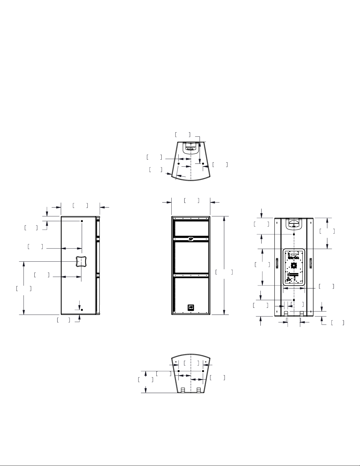
Dimensions:
H x W x D
Front:
43.50 in. x 16.75 in. x 16.85 in.
1105 mm x 426 mm x 428 mm
Rear Width:
11.58” – 294 mm
Weight:
93 lbs. (42.3 kg)
ELECTRONICS AND AMPLIFIER SPECIFICATIONS:
Electronic input impedance (nominal):
Balanced inputs: 10 k ohms line level sensitivity selected.
Unbalanced input: 5 k ohms, line level sensitivity selected.
Mic switch sensitivity Increase: 26 dB
Infrasonic lter protection: 36 dB/octave roll-o
Nominal amplier frequency response: +0, -1 dB from 10 Hz to 30 kHz
Hum and noise: Greater than 90 dB below rated power
DDT dynamic range: Greater than 14 dB
THD and IM: Typically less than 0.1 %
Damping factor: Greater than 50 @ 1000 Hz, 4 ohms
Page 20
Power requirements of Peavey® SP®4P system (domestic):
Nominal 200 watts, 120 VAC, 60 Hz
Fuse Type
For 120 VAC USE: International fuse classication T10AH 250V. In the USA, types GDC, GMC, 215, 218, and
477 cartridge-style 5 x 20 mm size time-delay fuses with a 10 amp 250V rating can be used.
For 220-240VAC USE: International fuse classication T5AH 250V . is is a cartridge style 5 x 20 mm size
time-delay fuse with a 5 amp 250V rating.
Specications subject to change without notice.
239.59
9.433
134.37
5.290
134.37
5.290
53.11
2.091
584.36
23.006
53.00
2.087
230.39
9.070
223.29
8.791
425.63
427.94
16.848
134.37
5.290
239.59
9.433
53.00
2.087
16.757
268.74
10.580
180.00
7.087
402.00
15.827
180.00
7.087
38.00
1.496
136.00
5.354
340.45
13.404
237.00
9.331
55.00
2.165
1082.91
134.37
5.290
42.634
Page 21

Logo referenced in Directive 2002/96/EC Annex IV
The bar is the symbol for marking of new waste and
13 August 2005
www.peavey.com
Warranty registration and information for U.S. customers available online at
www.peavey.com/warranty
or use the QR tag below
Features and specications subject to change without notice.
Peavey Electronics Corporation 5022 Hartley Peavey Drive Meridian, MS 39305 (601) 483-5365 FAX (601) 486-1278
(OJ(L)37/38,13.02.03 and defined in EN 50419: 2005
is applied only to equipment manufactured after
 Loading...