

Page 1
P E A V E Y E L E C T R O N I C S
SPECS
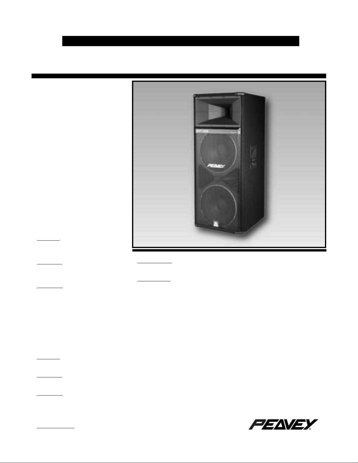
SP™ 4G
Sound Reinforcement
Enclosure with
Sound Guard™ HF
Protection System
SPECIFICATIONS
Frequency Response, 1 Meter
On-Axis, Swept-Sine in Anechoic
Environment:
50 Hz to 17.5 kHz
Low Frequency Cut-Off (-3 dB point):
50 Hz
Usable Low Frequency Limit
(-10 dB point):
39 Hz
Power Handling:
Full Range:
600 W continuous (49.0 V RMS)
1,200 W program
2,400 W peak
Bi-amp Low:
700 W continuous (52.9 V RMS)
1,400 W program
2,800 W peak
Bi-amp High:
40 W continuous (17.9 V RMS)
80 W program
160 W peak
Sound Pressure Level, 1 Watt, 1
Meter in Anechoic Environment:
Full Range: 100 dB (2.0 V)
Bi-amp Low: 100 dB (2.0 V)
Bi-amp High: 106 dB (2.8 V)
Maximum Sound Pressure Level
(1 meter):
Full Range:
127 dB continuous
133 dB peak
Bi-amp Low:
128 dB continuous
134 dB peak
Bi-amp High:
122 dB continuous
128 dB peak
Radiation Angle Measured at -6 dB
Point of Polar Response:
500 Hz to 1.6 kHz:
Horizontal: 92° ±13°
Vertical: 83° ±13°
1.6 kHz to 5 kHz:
Horizontal: 83° ±19°
Vertical: 57° ±17°
5 kHz to 16 kHz:
Horizontal: 86° ±3°
Vertical: 39° ±2°
Directivity Factor, Q (Mean):
9.5 ±3.3
Directivity Index, Di (Mean):
9.5 dB ±1.5 dB
Transducer Complement:
Two 1505-8 KADT Black Widow® woofers
One 22XT™ compression driver loaded
by a CH® 941 horn
Box Tuning Frequency:
50 Hz
Crossover Frequency (internal
passive):
1.8 kHz
Minimum Recommended Active
Crossover Frequency and Slope for
Bi-amping:
1.2 kHz at 18 dB/octave
Time Offset:
0.70 mS (delay Lows)
Impedance (Z):
Full Range Nominal: 4 Ω
Full Range Minimum: 3.9 Ω
Lows Nominal: 4 Ω
Highs Nominal: 8 Ω
Input Connections:
Two paralleled 1/4" phone jacks for
full-range input
One 1/4" phone jack for bi-amp low
frequency input
One 1/4" phone jack for bi-amp high
frequency input
Enclosure Materials and Finish:
3/4" plywood enclosure covered with black
carpet and protective polymer corners
Expanded metal grille to protect the low
frequency driver
Mounting Provisions:
None
Dimensions (H x W x D):
49.25" x 21.50" x 22.75"
(125.1 cm x 54.6 cm x 57.8 cm)
Page 2
Net Weight:
id
h(
)
135 lbs. (61.4 kg)
FEATURES
• Two 1505-8 KADT Black Widow
woofers
• 22XT™ compression driver
• Sound Guard™ high frequency
protection circuit
• Trapezoidal enclosure design
• Built-in pocket casters for easy
movement
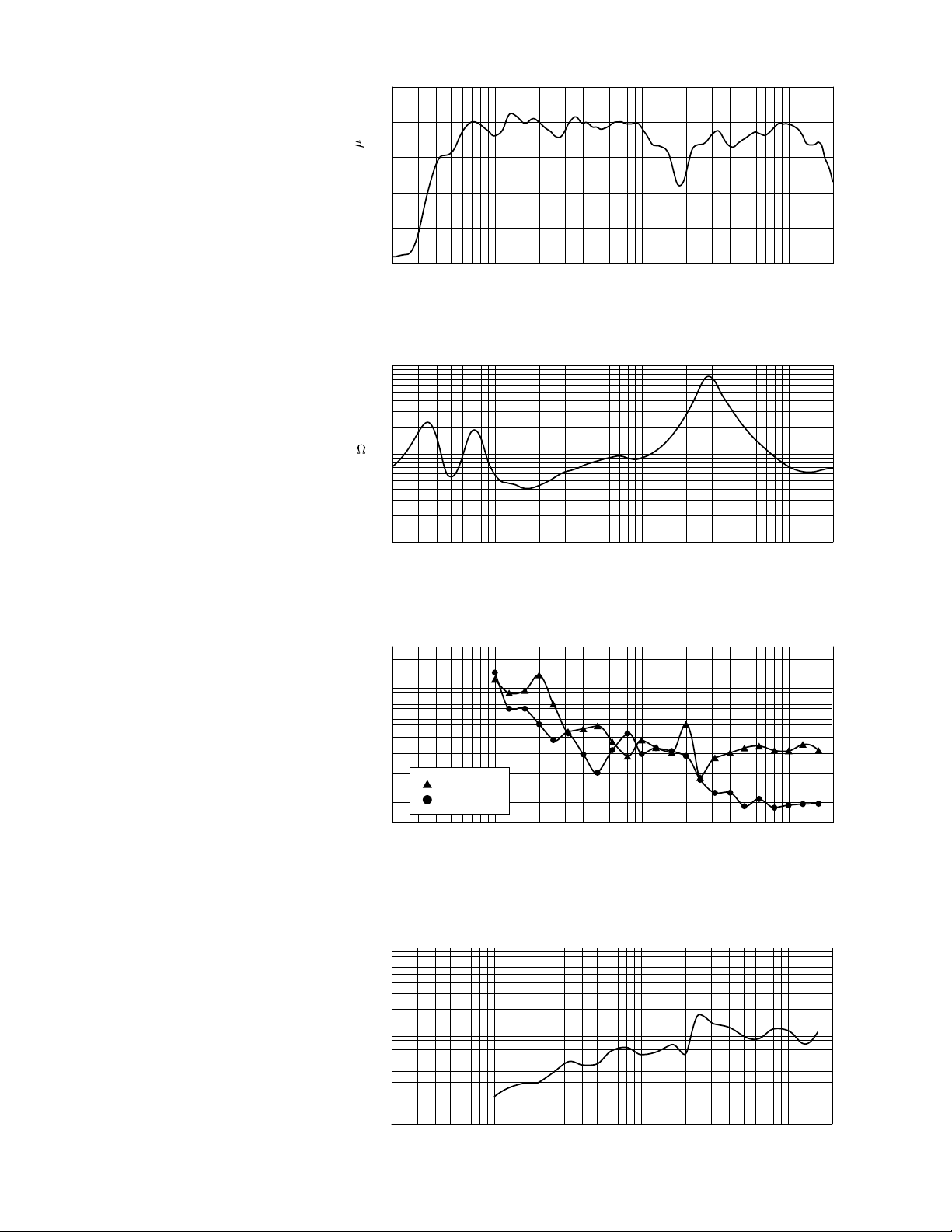
Amplitude Response (1W 1m On-Axis)
110
®
100
dB SPL (re 20 Pa)
90
80
70
DESCRIPTION
The redesign of the ever popular SP™ 4
has resulted in the SP™ 4G loudspeaker
system. It is a pseudo three-way speaker
system comprised of a 15" Scorpion
Plus woofer with a Kevlar® impregnated
cone and a 22XT™ compression driver
coupled to a CH® 941 constant directivity
horn.
This unit can be driven in full-range or
bi-amp mode simply by plugging into
the desired jack on the input plate. The
SP™ 4G has a trapezoidal shaped box,
rather than a rectangular shaped box,
that allows arrays to be constructed
much more easily. This shape also
greatly reduces the build-up of standing
waves on the inside of the enclosure.
This ensures a minimum of mid-bass
and mid-range coloration of the
reproduced sound due to the cabinet.
The SP™ 4G is constructed of 3/4"
plywood and is covered with Peavey’s
durable black carpet. Polymer corners
are also a part of the unit to provide
added protection to the enclosure. A
powder-coated, expanded metal grille
covers the lower part of the front of the
enclosure to protect the low frequency
driver from unforeseen accidents.
Sound Guard™, Peavey’s proprietary
circuit for high frequency driver
protection, has been included as an
integral part of the crossover for the
SP™ 4G. The input signal is routed
through the Sound Guard™ circuit in
both full-range and bi-amp modes of
operation. When the high frequency
drive level to the SP™ 4G exceeds a
predetermined threshold the Sound
Guard™ circuit in engaged. This subtly
decreases the signal level going to the
22XT™ so that it will not be damaged
due to long-term overpowering. Short
duration transients will not be
attenuated by Sound Guard™ and have
the possibility to damage the 22XT™.
The Sound Guard™ circuit is a dynamic
circuit that will attenuate the signal
more in relation to how large the signal
is, very similar to a compressor. This is
accomplished through the use of a
specially selected, dynamically resistive
®
60
20 50 100 200 500 1k 2k 5k 10k 20k
Figure 1
Frequency (Hz)
Impedance
100
50
30
20
Z
(
)
10
5
3
2
1
20 50 100 200 500 1k 2k 5k 10k 20k
Figure 2
Frequency (Hz)
Beamwidth
360
300
180
140
Degrees
100
t
80
60
Beamw
40
30
20 50 100 200 500 1k 2k 5k 10k 20k
Figure 3
Horizontal
Vertical
Frequency (Hz)
Q & Directivity Index
100
Q
10
1
20 50 100 200 500 1k 2k 5k 10k 20k
Figure 4
Frequency (Hz)
20
Di
10
0
Page 3

HORIZONTAL POLAR PATTERNS
-90
o
-60
o
-30
o
0
o
30
o
60
o
90
o
-90
o
-60
o
-30
o
0
o
30
o
60
o
90
o
0
o
30
o
60
o
90
o
-30
o
-60
o
-90
o
0
o
30
o
60
o
90
o
-30
o
-60
o
-90
o
1 octave averaged, plotted on ISO 1 octave centers from 250 Hz to 8 kHz
o
0
o
30
o
60
o
90
o
-30
o
-60
o
-90
o
90
o
30
o
60
o
0
o
-30
o
-60
o
-90
250 Hz 500 Hz 1 kHz
o
o
30
o
60
o
90
0
o
-30
o
-60
o
-90
o
90
o
30
o
60
o
0
o
-30
o
-60
o
-90
2 kHz
4 kHz
8 kHz
VERTICAL POLAR PATTERNS
o
90
o
-90
o
60
o
30
o
0
o
-30
o
-60
250 Hz
o
90
o
60
o
30
o
0
o
90
o
-90
o
60
o
30
o
0
o
-30
o
-60
1 kHz500 Hz
o
90
o
60
o
30
o
0
o
o
-90
2 kHz
-30
o
-60
o
-90
4 kHz
o
-30
o
-60
8 kHz
Page 4

light bulb. If the bulb in your Sound
Guard™ should ever burn out, a
replacement may be obtained from an
Authorized Peavey Service Center.
However, if a Peavey replacement bulb
is not readily available, an automotive
type 1156 bulb may be substituted for
temporary use until a Peavey bulb can
be obtained.
FREQUENCY RESPONSE
This measurement is useful in
determining how accurately a given
unit reproduces an input signal. The
frequency response of the SP™ 4G is
measured at a distance of 1 meter
using a 2.0 volt swept-sine input signal.
As shown in Figure 1, the selected
drivers in the SP™ 4G combine to give a
smooth frequency response from 39 Hz
to 17.5 kHz.
DIRECTIVITY
Beamwidth and directivity factors are
derived from the -6 dB points from the
polar plots (see Figure 3), which are
measured in a whole space anechoic
environment. These are specifications
that provide a reference to the coverage
characteristics of the unit. These
parameters provide insight for proper
placement and installation in the
chosen environment. The blending of
the components of the SP
desirable beamwidth and directivity
(Figures 3 and 4) suitable for sound
reinforcement applications.
™
4G exhibit a
POWER HANDLING
There are many different approaches
to power handling ratings. Peavey
Electronics rates this unit’s system
power handling using a modified form
of the AES Standard 2-1984. Utilizing
audio band limited (20 Hz to 20 kHz)
pink noise with peaks over four times
the RMS level, this strenuous test
signal assures the user that every
portion of this system can withstand
today’s high technology music. The
test signal contains large amounts of
very low frequency energy, effectively
simulating the frequency content of live
music situations. The full measure of
high frequencies in the test signal allow
for exposure of the speaker system to
synthesized tones that may extend
beyond audibility. This rating is
contingent on having a minimum of
3 dB of amplifier headroom available
so as to ensure that clipping does not
occur.
ARCHITECTURAL and
ENGINEERING SPECIFICATIONS
The loudspeaker system shall have
an operating bandwidth of 39 Hz to
17.5 kHz. The nominal output level
shall be 100 dB when measured at a
distance of one meter with an input
of one watt. The nominal impedance
shall be 4 ohms. The maximum
continuous power handling shall be
600 watts, maximum program power
of 1,200 watts and a peak power input
of at least 2,400 watts, with a minimum
amplifier headroom of 3 dB. The
nominal radiation geometry shall be
87 degrees in the horizontal plane
and 60 degrees in the vertical plane.
The outside dimensions shall be
49.25 inches high by 21.5 inches
wide by 22.75 inches deep. The
weight shall be 135 pounds. The
loudspeaker system shall be a
Peavey model SP™ 4G.
THREE + TWO YEAR LIMITED
WARRANTY
NOTE: For details, refer to the
warranty statement. Copies of this
statement may be obtained by
contacting Peavey Electronics
Corporation, P.O. Box 2898, Meridian,
Mississippi 39302-2898.
Features and specifications subject to change without notice.
Peavey Electronics Corporation • 711 A Street • Meridian, MS 39301 • U.S.A.
(601) 483-5365 • Fax 486-1278 • www.peavey.com
©1998 Printed in U.S.A. 9/98
80301834
 Loading...