

Peavey SMR 821a Specification
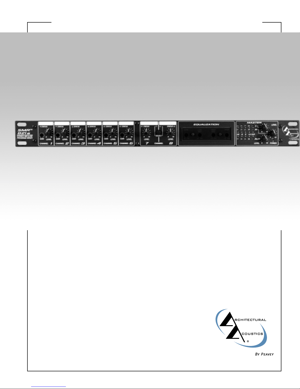
SMR™821a stereo mic/line program audio mixerSpecifications
DDEESSCCRRIIPPTTIIOONN
The SMR™821a is a professional
microphone and line level audio program
mixer intended for fixed installation
applications. This single‚ rack-mount unit
is designed to provide high-quality audio
performance using versatile control
options and a simple user-interface.
Engineered from the ground up with the
commercial sound systems contractor in
mind‚ the SMR 821a includes many
features for easy operation‚ installation
and servicing.
With three independent audio output
buses‚ the SMR 821a is perfect for
applications where zoned output and
simple monitoring is required. Six of the
eight inputs include high-quality
microphone pre-amplifiers and separate
gain controls. Additional rear panel
controls provide even more flexibility for
proper gain setup‚ output assign and
remote control features.
In stand-alone applications‚ the SMR
821a is a very powerful tool. Ease of use‚
external control options and a simple
user-interface make it perfect for many
applications where the end-user must
have access to the audio system. The
ability to link multiple units provides
even more flexibility for a wide range of
applications.
FFEEAATTUURREESS
• Single rack space design
• Eight total inputs: six balanced
mic/line; two unbalanced stereo
• LED level/clip status indicator on
each channel
• Mic inputs include selectable 48-Volt
phantom power
• Two selectable stereo line inputs
(mono or stereo switchable)
• Three assignable electronicallybalanced outputs: Left‚ Right‚ Aux
• Master level controls for each
output bus
• Three five-segment LED meter
arrays
• Four-band EQ: low‚ low-mid‚
high-mid‚ high
• Integral channel muting system
with priority
• Audio and mute bus linking
• Left‚ Right‚ Aux and Mute bus
links for stacking multiple units
• Rear panel master/slave linking
mode switch
• Remote master Left/Right level
control port
• Rear panel 20 dB pad switch on
each microphone input
• Front panel continuously variable
preamp gain control
• Rear panel bus assign switches
for each microphone channel
• Rear panel global 100 Hz low-cut
filter switch for all microphone
inputs
• Mute bus with channel 1 rear
panel threshold control
• Select switch for routing
microphone mix bus post
remote control
• All audio I/O on removable Eurotype connectors
AARRCCHHIITTEECCTTUURRAALL AANNDD
EENNGGIINNEEEERRIINNGG SSPPEECCIIFFIICCAATTIIOONNSS
The mixer shall have six
electronically balanced microphone
or line inputs. The mixer shall also
have two stereo unbalanced line
inputs. All inputs shall be routable to
any or all of three master buses, Left,
Right, and Aux. Each microphone
input shall include selectable 48-Volt
phantom power. Channel One shall
have a variable mute threshold over
all other channels. Each input shall
have a Signal/Clip indicator that
activates green at –20 dB, and turns
red at 2 dB below clipping. The mixer
shall have three electronically
balanced outputs, Left, Right and
Aux, each with its own master output
control and five LED meter array. The
mixer shall have remote master
capability for each of the master L, R
buses. There shall be remote select
for the two stereo inputs, rear panel
global 100 Hz low cut filter for the
mic inputs, master/slave link mode
switch, and audio bus linking. The
mixer shall have a shelving low EQ
with 15 dB boost or cut starting at
70 Hz, a peak/dip low mid EQ with
15 dB boost or cut at 250 Hz, a
peak/dip high mid EQ with 15 dB
boost or cut at 3.1 kHz and a high
shelving eq with 15 dB boost or cut
at 10 kHz. The unit shall be housed in
a rugged metal chassis 1.75" tall by
19" wide by 8.75" deep. One-inch
mounting flanges will be provided on
each side. The unit shall operate
from 120 VAC, 60 Hz power. The
mixer shall be capable of driving
+21 dBu into a balanced load from
the Left, Right or Aux outputs, from
20 Hz to 20 kHz. +0 to –2 dB into
600 Ohms with less than 0.05%
distortion and with system hum and
noise at least 80 dB below rated
output. The unit shall be a Peavey
Architectural Acoustics model SMR
821a.
SMR™821a stereo mic/line program audio mixerSpecifications
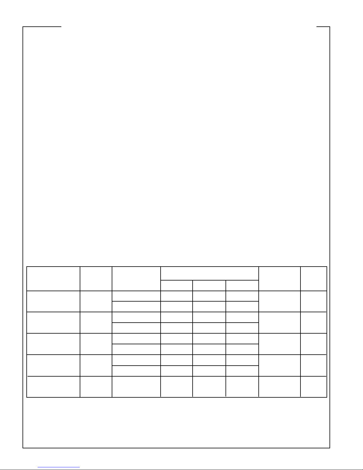
0 dBu = 0.775 VRMS
0 dBV = 1.00 VRMS
* Min. input level (sensitivity) is the smallest signal that will produce a nominal output with controls set at maximum gain.
** Nominal settings are defined as all controls set at center detent for nominal output. Microphone gain control is as specified.
Input
Microphone
without pad
Microphone
with pad
2 k
2 k
2 k
2 k
10 k
Max Gain +60 dB
Min Gain +10 dB
Max Gain +40 dB
Min Gain -10 dB
Max Gain +60 dB
Min Gain +20 dB
Max Gain +40 dB
Min Gain 0 dB
N/A
-76 dBu
-25 dBu
-56 dBu
-5 dBu
-74 dBu
-34 dBu
-54 dBu
-14 dBu
-20 dBu
-56 dBu
-4 dBu
-36 dBu
+16 dBu
-54 dBu
-14 dBu
-34 dBu
+6 dBu
-10 dBu
-39 dBu
+13 dBu
-19 dBu
+33 dBu
-37 dBu
+3 dBu
-17 dBu
+23 dBu
+7 dBu
balanced
balanced
balanced
balanced
unbalanced
+
-
ground
+
-
ground
+
-
ground
+
-
ground
RCA jacks
Microphone
without pad (optional
transformer)
Microphone
with pad (optional
transformer)
Stereo Line
Input
Impedance
(Ohms)
Input Gain
Pot Setting
Input Level: dBu
Min* Nom** Max
Balanced/
Unbalanced
Connector
IInnppuutt SSeennssiittiivviittyy
 Loading...