

Page 1
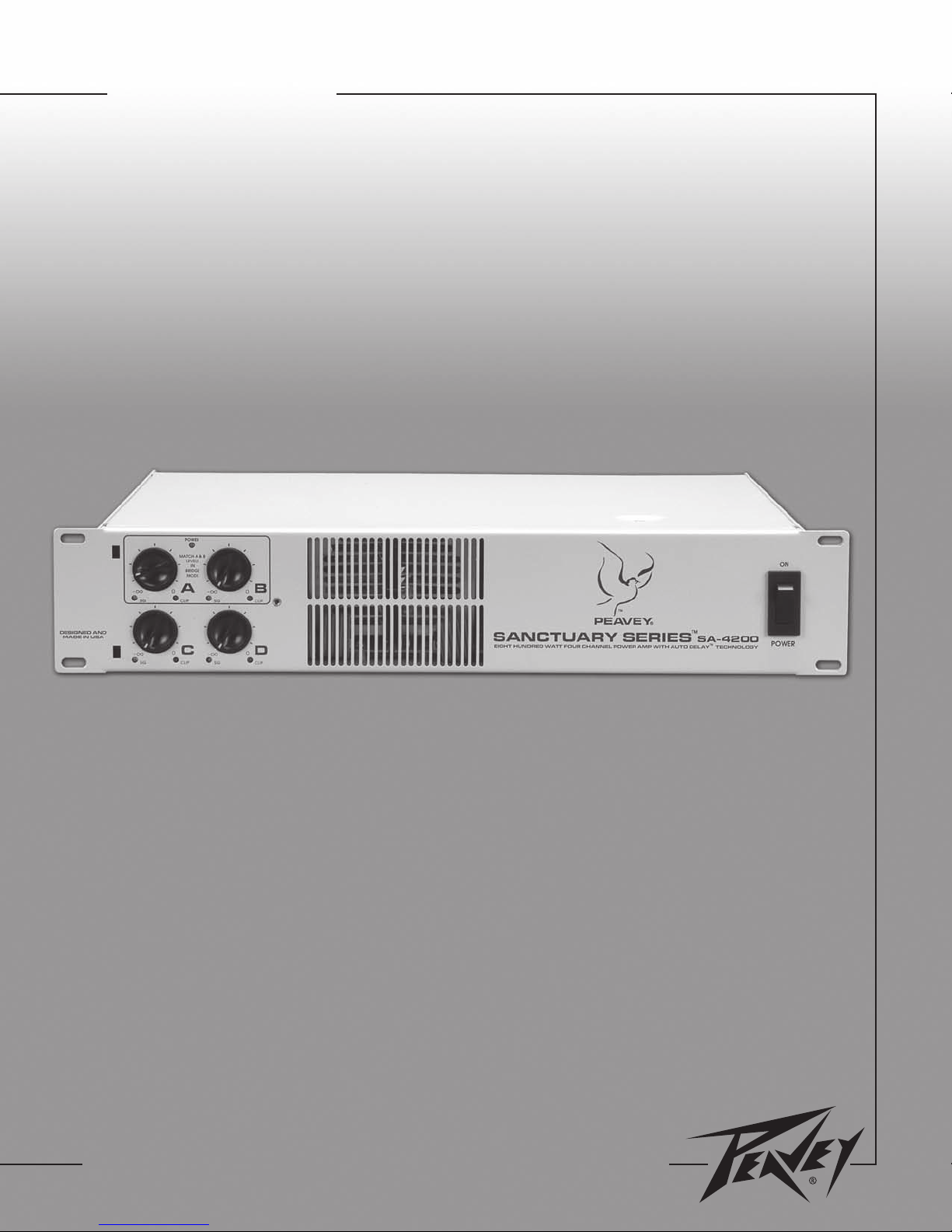
SA-4200
™
Power Amplifier Operating Guide
For information on other great Peavey products, go to your local Peavey dealer or visit us online at www.peavey.com or sanctuary-series.com
Page 2
Intended to alert the user to the presence of uninsulated “dangerous voltage” within the product’s
enclosure that may be of sufficient magnitude to constitute a risk of electric shock to persons.
Intended to alert the user of the presence of important operating and maintenance (servicing)
instructions in the literature accompanying the product.
CAUTION: Risk of electrical shock — DO NOT OPEN!
CAUTION: To reduce the risk of electric shock, do not remove cover. No user serviceable parts inside.
Refer servicing to qualified service personnel.
WARNING: To prevent electrical shock or fire hazard, this apparatus should not be exposed to rain or
moisture‚ and objects filled with liquids‚ such as vases‚ should not be placed on this apparatus. Before
using this apparatus‚ read the operating guide for further warnings.
Este símbolo tiene el propósito, de alertar al usuario de la presencia de “(voltaje) peligroso” sin
aislamiento dentro de la caja del producto y que puede tener una magnitud suficiente como para
constituir riesgo de descarga eléctrica.
Este símbolo tiene el propósito de alertar al usario de la presencia de instruccones importantes sobre la
operación y mantenimiento en la información que viene con el producto.
PRECAUCION: Riesgo de descarga eléctrica ¡NO ABRIR!
PRECAUCION: Para disminuír el riesgo de descarga eléctrica, no abra la cubierta. No hay piezas útiles
dentro. Deje todo mantenimiento en manos del personal técnico cualificado.
ADVERTENCIA: Para prevenir choque electrico o riesgo de incendios, este aparato no se debe exponer a
la lluvia o a la humedad. Los objetos llenos de liquidos, como los floreros, no se deben colocar encima
de este aparato. Antes de usar este aparato, lea la guia de funcionamiento para otras advertencias.
Ce symbole est utilisé dans ce manuel pour indiquer à l’utilisateur la présence d’une tension dangereuse
pouvant être d’amplitude suffisante pour constituer un risque de choc électrique.
Ce symbole est utilisé dans ce manuel pour indiquer à l’utilisateur qu’il ou qu’elle trouvera d’importantes
instructions concernant l’utilisation et l’entretien de l’appareil dans le paragraphe signalé.
ATTENTION: Risques de choc électrique — NE PAS OUVRIR!
ATTENTION: Afin de réduire le risque de choc électrique, ne pas enlever le couvercle. Il ne se trouve
à l’intérieur aucune pièce pouvant être reparée par l’utilisateur. Confiez I’entretien et la réparation de
l’appareil à un réparateur Peavey agréé.
AVIS: Dans le but de reduire les risques d’incendie ou de decharge electrique, cet appareil ne doit
pas etre expose a la pluie ou a l’humidite et aucun objet rempli de liquide, tel qu’un vase, ne doit
etre pose sur celui-ci. Avant d’utiliser de cet appareil, lisez attentivement le guide fonctionnant pour
avertissements supplémentaires.
Dieses Symbol soll den Anwender vor unisolierten gefährlichen Spannungen innerhalb des Gehäuses
warnen, die von Ausreichender Stärke sind, um einen elektrischen Schlag verursachen zu können.
Dieses Symbol soll den Benutzer auf wichtige Instruktionen in der Bedienungsanleitung aufmerksam
machen, die Handhabung und Wartung des Produkts betreffen.
VORSICHT: Risiko — Elektrischer Schlag! Nicht öffnen!
VORSICHT: Um das Risiko eines elektrischen Schlages zu vermeiden, nicht die Abdeckung enfernen.
Es befinden sich keine Teile darin, die vom Anwender repariert werden könnten. Reparaturen nur von
qualifiziertem Fachpersonal durchführen lassen.
WARNUNG: Um elektrischen Schlag oder Brandgefahr zu verhindern, sollte dieser Apparat nicht
Regen oder Feuchtigkeit ausgesetzt werden und Gegenstände mit Flüssigkeiten gefuellt, wie Vasen,
nicht auf diesen Apparat gesetzt werden. Bevor dieser Apparat verwendet wird, lesen Sie bitte den
Funktionsführer für weitere Warnungen.
2
Page 3
IMPORTANT SAFETY INSTRUCTIONS
WARNING: When using electrical products, basic cautions should always be followed, including the following:
1. Read these instructions.
2. Keep these instructions.
3. Heed all warnings.
4. Follow all instructions.
5. Do not use this apparatus near water.
6. Clean only with a dry cloth.
7. Do not block any of the ventilation openings. Install in accordance with manufacturer’s instructions.
8. Do not install near any heat sources such as radiators, heat registers, stoves or other apparatus (including amplifiers)
that produce heat.
9. Do not defeat the safety purpose of the polarized or grounding-type plug. A polarized plug has two blades with one
wider than the other. A grounding type plug has two blades and a third grounding plug. The wide blade or third prong is
provided for your safety. If the provided plug does not fit into your outlet, consult an electrician for replacement of the
obsolete outlet.
10. Protect the power cord from being walked on or pinched, particularly at plugs, convenience receptacles, and the point
they exit from the apparatus.
11. Note for UK only: If the colors of the wires in the mains lead of this unit do not correspond with the terminals in your
plug‚ proceed as follows:
a) The wire that is colored green and yellow must be connected to the terminal that is marked by the letter E‚ the earth
symbol‚ colored green or colored green and yellow.
b) The wire that is colored blue must be connected to the terminal that is marked with the letter N or the color black.
c) The wire that is colored brown must be connected to the terminal that is marked with the letter L or the color red.
12. Only use attachments/accessories provided by the manufacturer.
13. Use only with a cart, stand, tripod, bracket, or table specified by the manufacturer, or sold with the apparatus. When a
cart is used, use caution when moving the cart/apparatus combination to avoid injury from tip-over.
14. Unplug this apparatus during lightning storms or when unused for long periods of time.
15. Refer all servicing to qualified service personnel. Servicing is required when the apparatus has been damaged in any
way, such as power-supply cord or plug is damaged, liquid has been spilled or objects have fallen into the apparatus,
the apparatus has been exposed to rain or moisture, does not operate normally, or has been dropped.
16. Never break off the ground pin. Write for our free booklet “Shock Hazard and Grounding.” Connect only to a power
supply of the type marked on the unit adjacent to the power supply cord.
17. If this product is to be mounted in an equipment rack, rear support should be provided.
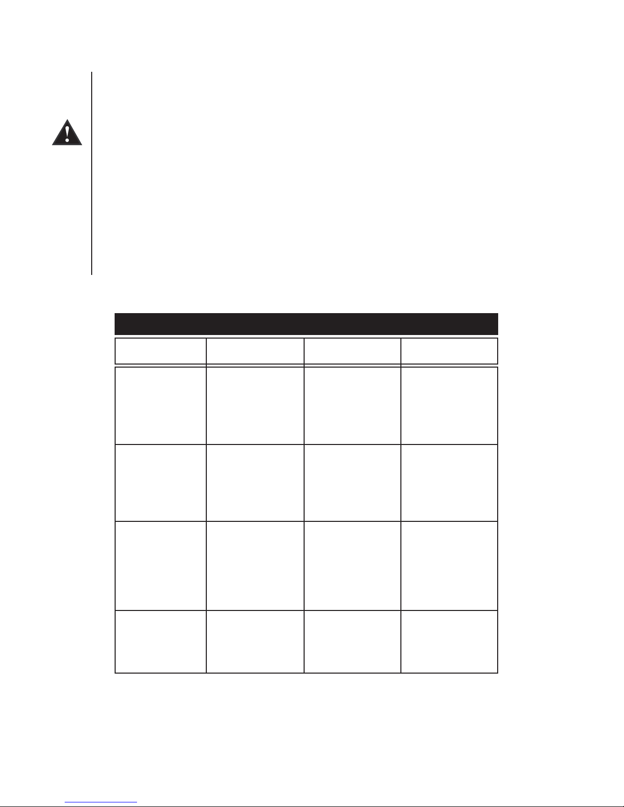
18. Exposure to extremely high noise levels may cause a permanent hearing loss. Individuals vary considerably in suscep
tibility to noise-induced hearing loss, but nearly everyone will lose some hearing if exposed to sufficiently intense noise
for a sufficient time. The U.S. Government’s Occupational Safety and Health Administration (OSHA) has specified the
following permissible noise level exposures:
-
Duration Per Day In Hours Sound Level dBA, Slow Response
8 90
6 92
4 95
3 97
2 100
1 1⁄2 102
1 105
1⁄2 110
1⁄4 or less 115
According to OSHA, any exposure in excess of the above permissible limits could result in some hearing loss. Ear plugs or protectors to
the ear canals or over the ears must be worn when operating this amplification system in order to prevent a permanent hearing loss, if
exposure is in excess of the limits as set forth above. To ensure against potentially dangerous exposure to high sound pressure levels, it is
recommended that all persons exposed to equipment capable of producing high sound pressure levels such as this amplification system be
protected by hearing protectors while this unit is in operation.
SAVE THESE INSTRUCTIONS!
3
Page 4

ENGLISH
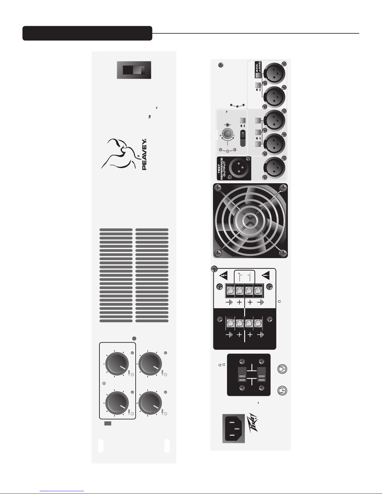
SA-4200™ Power Amplifier
Description
Keeping with the Sanctuary Series creed, this four-channel power amplifier solves common audio problems with exclusive Peavey
technology. Built-in Auto Delay™ automatically measures and sets the proper delay time for fill loudspeakers, eliminating the
frustrating delay and phasing problems experienced in many houses of worship.
The SA-4200 also features four channels rated at 200 watts each into 4 ohms or 70 volts (selectable in two-channel pairs). This
versatility makes the SA-4200 ideal for delivering power to both main and balcony/fill loudspeakers and any application requiring
multiple audio zones, such as cry rooms or paging systems in larger houses of worship.
Features
• Four-channel power amplifier system rated at 200 watts RMS per channel
• Low-Z (4 or 8 ohms) or 70V outputs selectable in two-channel pairs
• Patent-pending, proprietary built-in Auto Delay circuitry
• Dedicated XLR-type, electronically balanced input connectors
• Low-cut filter on each channel
• Front panel detented level controls
• Front panel AC power switch/circuit breaker
• Short circuit, thermal and DC load protection circuitry
• Rugged, 2U rack-mount design
• Two-speed, fan-cooled patented heat-management design (U.S. Patent Number 6,515,859)
• Signal and clip LED indicators for each channel
with security cover
on front panel
Unpacking
Upon unpacking, inspect the amplifier. If you find any damage, notify your supplier immediately. Only the consignee may institute
a claim with the carrier for damage incurred during shipping. Be sure to save the carton and all packing materials. Should you ever
need to ship the unit back to Peavey Electronics, one of its offices, service centers or the supplier, use only the original factory
packing. If the shipping carton is unavailable, contact Peavey to obtain a replacement.
Mounting
The SA-4200 amplifier will mount in standard 19” E.I.A. equipment racks.
Security Cover
A security cover is provided to prevent inadvertent level adjustments. It is designed to permit monitoring of the various LEDs
without removal. To remove the cover‚ simply remove the Phillips-head mounting screw.
Cooling Requirements
The SA-4200 amplifier uses a forced-air cooling system to maintain a low, even operating temperature. Air is drawn into
the amplifier via a fan located in the back of the unit and courses through the cooling fins of the tunnel-configured channel
heat sinks. The air then exits through the front panel slots. If the heat sinks get too hot‚ a sensing circuit will activate the
protective muting system to protect the amplifier. When the internal temperature reaches a safe level‚ the amplifier will
automatically return to normal operation. It is important that both the front and rear of the unit have enough space to allow
the cooling air to enter and escape. If the amp is rack mounted, do not use doors or covers on the front of the rack; the
intake air must flow without resistance. If you are using racks with closed backs, make sure that there is one (1) standard
rack space opening for every three mounted power amplifiers. If not rack mounted‚ allow 6” of clearance on all sides.
4
Page 5
Operating Precautions
Make sure the mains voltage is correct and is the same as that printed on the rear of the amplifier. Damage caused
by connecting the amplifier to improper AC voltage is not covered by any warranty.
Note: Always turn off and disconnect the amplifier from mains voltage before making audio connections. Also, as an
extra precaution, have the attenuators turned down during power-up.
It is always a good idea to have the gain controls turned down during power-up to prevent loudspeaker damage if
there is a high signal level at the inputs. Whether you buy or make them, use high-quality connections, input cables
and loudspeaker cables along with proper soldering technique to ensure trouble-free operation. Most intermittent
problems are caused by faulty cables.
Consult the Wire Gauge Chart (below) to determine proper gauges for various load impedances and cable lengths.
2
Remember that cable impedance robs amplifier power in two ways: power lost directly to resistance (I
R loss) and
by raising the total load impedance.
W I R E G A U G E C H A R T
Cable Length
(In Feet)
5 18 .79 1.58
16 .50 1.00
14 .31 .62
12 .20 .40
10 .125 .25
10 18 1.58 3.16
16 1.00 2.00
14 .62 1.25
12 .40 .80
10 .25 .50
40 18 8.00 12.60
16 4.00 8.00
14 2.50 5.00
12 1.60 3.20
10 1.00 2.00
8 .625 1.25
80 16 8.00 16.00
14 5.00 10.00
12 3.20 6.40
10 2.00 4.00
Stranded Wire Gauge
(AWG)
Power Loss into
8 ohms (%)
Power Loss into
4 ohms (%)
5
Page 6
CHANNEL & MASTER FUNCTIONS
AUTO
DELA
Y
DELA YED I NPUTS
TEST MIC
A
B
OU TPUT S
C
D
LOW Z
70V
OUTPUTS C/D
OUTP UT MO DE
SELE C
T
OUTPUTS A/ B
INPUT D INPUT C
INPUT B INPUT
A
OK
LON
G
SHORT
INPUT
LOCK
CD
SELECT
DELAY MODE
PUSH - AUTO
TURN - MANUAL
LOW CUT
(60Hz)
DELAYDELAY
BYPAS S
ACTIVE
BYPASS
ACTIVE
IN
OUT
MIC NOT CONNECTED OR OPERATIONA
L
MIC UNABLE TO RECEIVE TEST TONE
AVAILABLE DELAY IS NOT ADEQUATE
FOR PROPER CORRECTIO
N
LOW CUT
(60Hz)
IN
OUT
TEST
NORM
B NOT USED IN
BRIDGE MODE
THIS UNIT COMPLIES WITH THE
LIMITS FOR A CLASS B DIGITAL DEVICE
PURSUANT TO SUBPART J OF FCC RULES
A PRODUCT OF PEAVEY ELECTRONICS CORP .
DESIGNED AND MADE IN U.S.A.
WWW.SANCTUARY-SERIES.COM
120 VAC 60 Hz
1200 WATTS
CLASS 2 WIRING PERMITTED FOR 70V OUTPUTS
200 WATTS/CHANNEL AT 4 OR 70V OUTPUTS
CLASS 3 WIRING REQUIRED FOR 140V OUTPUT
BRIDGE
MODE
DUAL A/B MODE 4 /70V
BRIDGE A/B MODE 8 /140V
INPUT
1 -GND
2 - POS
3 - NEG
OUTPUT
1 -GND
2 - POS
3 - NEG
XLR
DELAY FAULT CONDITIONS
MOUNT IN RACK ONLY - INSTALLER SUR
SUPPORT DE MONTAGE SEULEMEN
T
AND PATENT PENDING
SANCTUARY SERIES
BUILT UNDER U.S. PATENT NO. 6,515,859
SA NCTUARY S ER IES
SA -42 00
EIGHT HUNDRED WATT FOUR CHA NNEL POWE R AMP WI TH AUTO DELAY TECHNOLOG Y
A
C
B
D
MATCH A & B
LEVEL
S
IN
BRIDGE
MODE
DESIGNED AND
MADE IN U .S.A.
POWER
ON
CLIPSIG CLIPSIG
POWE
R
0
SIG
CLIP
SIG
CLIP
0
0 0
6
Page 7
FRONT PANEL
SA NCT UAR Y SER IES
SA- 4200
EIGHT HUN DRED WATT FOU R CHANNE L POWER AMP WITH AUTO DEL AY TEC HNOLOGY
A
C
B
D
MATCH A & B
LEVELS
IN
BRIDGE
MODE
DESIGNED AND
MADE IN U.S.A.
POWER
ON
CLIPSIG CLIPSIG
POWE
R
0
SIG
CLIP
SIG
CLIP
0
0 0
WARNING
THE ON/ OFF SWI TCH IN THI S APPARATUS
DOE S NO T BR EAK BOTH SIDES OF THE MAINS.
HAZARDOUS ENERGY MAY BE
PRESENT I NSIDE
THE ENCLOSURE W HEN THE POW ER SWITCH IS
IN THE OFF PO SITION.
4
1
2
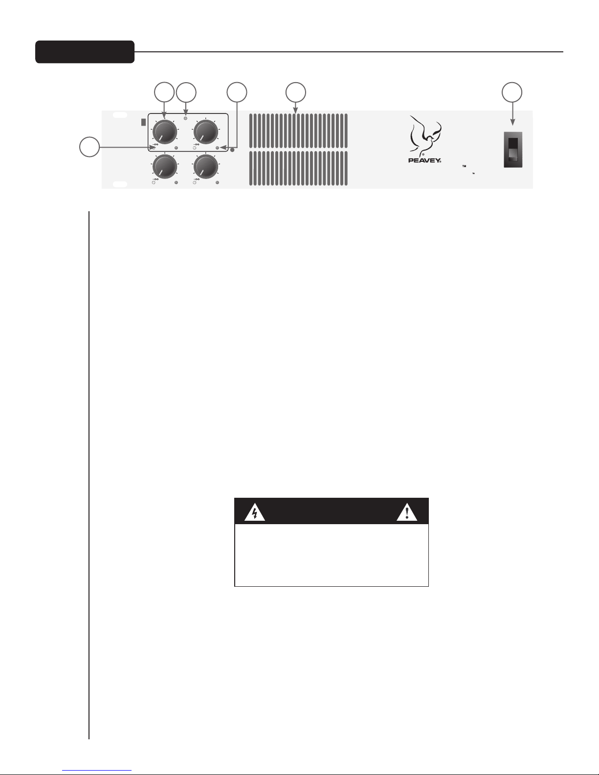
1. POWER INDICATOR:
The green LED indicates that AC power is supplied to the unit‚ the power switch is ON and the unit is
functional with no faults. If the amplifier has a thermal fault condition‚ this LED will not illuminate.
2. SIGNAL INDICATORS:
Yellow LEDs indicate signal presence at that specific channel output (identical on each channel).
3. CLIP (DDT™) INDICATORS:
Any time a channel is driven into hard, continuous clipping, the DDT circuit will automatically reduce the
channel gain to a level just slightly into clipping, guarding the loudspeakers against the damaging high power
continuous square waves that may be produced. Situations that may activate the DDT circuit include
uncontrolled feedback, oscillations or an improper equipment setting or malfunction upstream from
the amplifier. On the SA-4200™, normal program transients will not trigger DDT; only steady, excessive
clipping will. The LEDs will illuminate red when the DDT circuitry is active (identical on each channel).
3
6
5
4. INPUT LEVEL CONTROLS:
These controls adjust the signal level to the power amplifier inputs. Maximum input sensitivity is achieved
at the fully clockwise setting. These controls are detented to allow the input sensitivity of the channels to
be closely matched. This is essential in the bridged-output mode. See MODE CONFIGURATION on pages
18-21.
5. AC POWER SWITCH/CIRCUIT BREAKER:
The SA-4200 amplifier has a combination AC switch/circuit breaker on the front panel. If the switch shuts
off during normal use, push it back to the ON position once. If it will not stay on, the amplifier needs
servicing.
6. COOLING AIR VENT:
The SA-4200 is designed to operate under extreme conditions. Part of this design includes the air vents
visible from the front of the unit. These openings should never be blocked.
7
Page 8
REAR PANEL
AUTO
DELA
Y
DELAYE D INP UTS
TEST M IC
A
B
OUT PUTS
C
D
LOW Z
70V
OUTPUTS C/
D
OUTPUT MODE
SELECT
OUTPUTS A/B
INPUT D INPUT C
INPUT B INPUT
A
OK
LONG
SHOR
T
INPUT
LOCK
CD
SELECT
DELAY MODE
PUSH - AUTO
TURN - MANUAL
LOW CUT
(60Hz)
DELAYDELAY
BYPASS
ACTIVE
BYPASS
ACTIVE
IN
OU
T
MIC NOT CONNECTED OR OPERATIONA
L
MIC UNABLE TO RECEIVE TEST TONE
AVAILABLE DELAY IS NOT ADEQUATE
FOR PROPER CORRECTION
LOW CUT
(60Hz)
IN
OU
T
TEST
NORM
B NOT USED IN
BRIDGE MOD
E
THIS UNIT COMPLIES WITH THE
LIMITS FOR A CLASS B DIGITAL DEVIC
E
PURSUANT TO SUBPART J OF FCC RULE
S
A PRODUCT OF PEAVEY ELECTRONICS CORP .
DESIGNED AND MADE IN U.S.A.
WWW.SANCTUARY-SERIES.COM
120 VAC 60 Hz
1200 WATTS
CLASS 2 WIRING PERMITTED FOR 70V OUTPUTS
200 WATTS/CHANNEL AT 4 OR 70V OUTPUTS
CLASS 3 WIRING REQUIRED FOR 140V OUTPUT
BRIDGE
MODE
DUAL A/B MODE 4 /70V
BRIDGE A/B MODE 8 /140V
INPUT
1 -GND
2 - POS
3 - NEG
OUTPUT
1 -GND
2 - POS
3 - NEG
XLR
DELAY FAULT CONDITIONS
MOUNT IN RACK ONLY - INSTALLER SUR
SUPPORT DE MONTAGE SEULEMEN
T
AND PATENT PENDING
SANCTUARY SERIES
BUILT UNDER U.S. PATENT NO. 6,515,859
7
8
11
9
10
12
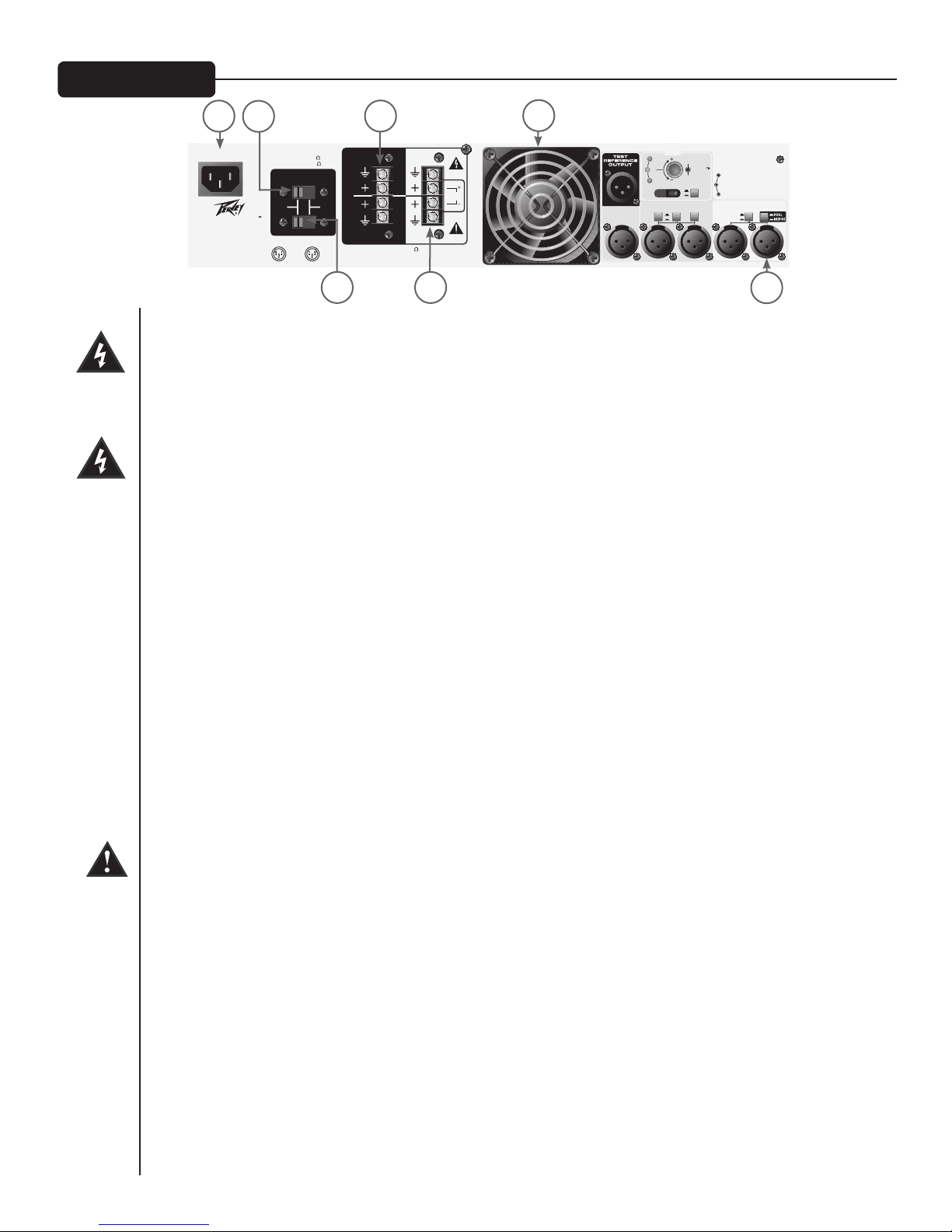
7. AC MAINS POWER RECEPTACLE:
This is a standard IEC power connector. An AC mains cord with the appropriate AC plug and ratings
for the intended operating voltage is included in the carton. The mains cord should be connected to the
amplifier before connecting to a suitable AC outlet.
AC MAINS CORD:
The mains cord supplied with the unit is a heavy duty‚ three-conductor type with a conventional
120 VAC plug with ground pin. Never break off the ground pin on any equipment. It is provided for
your safety. If the outlet used does not have a ground pin‚ a suitable grounding adapter should be
used and the third wire should be properly grounded.
8. CHANNEL A/B OUTPUT MODE SELECT (low-Z or 70 volt):
This slide switch allows channels A and B of this amp to be configured for either conventional low-Z or for
a 70 volt distribution loudspeaker system.
13
9. CHANNEL C/D OUTPUT MODE SELECT (low-Z or 70 volt):
This slide switch allows channels C and D of this amp to be configured for either conventional low-Z or for
a 70 volt distribution loudspeaker system.
10. CHANNEL A/B OUTPUTS:
The outputs are screw-type for channels A and B. Connect the loudspeaker system to the respective
positive and ground terminals. These outputs may also be used in BRIDGE Mode for a single output. See
Dual/Bridge Mode Switch (14) and MODE CONFIGURATIONS below for more details.
11. CHANNEL C/D OUTPUTS:
The outputs are screw-terminal type for channels C and D. Connect the loudspeaker system to the
respective positive and ground terminals.
12. FAN GRILLE:
A two-speed DC fan supplies cool air to the amplifier. This intake should never be blocked. The fan
automatically switches to high-speed when the unit requires additional cooling. When the amplifier is
relatively cool and at idle‚ the fan should operate at low speed. The fan should never stop unless the
amplifier is switched off or the AC mains power source is interrupted.
13. CHANNEL INPUTS:
These female XLR jacks allow for electronically balanced line-level input signals to be connected to the
system. Each input has a sensitivity of approximately 1.4 volts. Pin 2 is positive, Pin 3 is negative, and Pin 1
is ground.
8
Page 9

AUTO
DELA
Y
DELAYE D INP UTS
TEST M IC
A
B
OUT PUTS
C
D
LOW Z
70V
OUTPUTS C/
D
OUTPUT MODE
SELECT
OUTPUTS A/B
INPUT D INPUT C
INPUT B INPUT
A
OK
LONG
SHOR
T
INPUT
LOCK
CD
SELECT
DELAY MODE
PUSH - AUTO
TURN - MANUAL
LOW CUT
(60Hz)
DELAYDELAY
BYPASS
ACTIVE
BYPASS
ACTIVE
IN
OU
T
MIC NOT CONNECTED OR OPERATIONA
L
MIC UNABLE TO RECEIVE TEST TONE
AVAILABLE DELAY IS NOT ADEQUATE
FOR PROPER CORRECTION
LOW CUT
(60Hz)
IN
OU
T
TEST
NORM
B NOT USED IN
BRIDGE MOD
E
THIS UNIT COMPLIES WITH THE
LIMITS FOR A CLASS B DIGITAL DEVIC
E
PURSUANT TO SUBPART J OF FCC RULE
S
A PRODUCT OF PEAVEY ELECTRONICS CORP .
DESIGNED AND MADE IN U.S.A.
WWW.SANCTUARY-SERIES.COM
120 VAC 60 Hz
1200 WATTS
CLASS 2 WIRING PERMITTED FOR 70V OUTPUTS
200 WATTS/CHANNEL AT 4 OR 70V OUTPUTS
CLASS 3 WIRING REQUIRED FOR 140V OUTPUT
BRIDGE
MODE
DUAL A/B MODE 4 /70V
BRIDGE A/B MODE 8 /140V
INPUT
1 -GND
2 - POS
3 - NEG
OUTPUT
1 -GND
2 - POS
3 - NEG
XLR
DELAY FAULT CONDITIONS
MOUNT IN RACK ONLY - INSTALLER SUR
SUPPORT DE MONTAGE SEULEMEN
T
AND PATENT PENDING
SANCTUARY SERIES
BUILT UNDER U.S. PATENT NO. 6,515,859
REAR PANEL
14. DUAL/BRIDGE MODE SWITCH:
18
16
17
15
14
This push-button switch places channels A and B in either Dual Mode or Bridge Mode. In Dual Mode,
channels A and B are independent amplifier channels with their respective input signals connected to
the respective input jacks. In Bridge Mode, the signal from input A is inverted and applied to input B
so that channels A and B can be used together as a single amplifier with double the power. Be sure to
connect the load to the bridge terminals only. In Bridge Mode, the minimum load impedance is 8 ohms in
low-Z mode. If the output mode is set to 70V, the bridge output voltage is actually 140V. Be sure to use
transformers and wiring rated for this application.
NOTE: In Bridge Mode, both the A and B volume controls are active. Set both controls to the same
position.
15. LOW-CUT (60 Hz) SWITCHES:
Each switch places a 12 dB/octave, 60 Hz low-cut filter in the inputs of each amplifier channel pair. When
the 70V output mode is used, this filter is highly recommended to prevent low frequency energy from
saturating the matching transformers. This filter is also useful in low impedance mode for loudspeakers
that are not designed to reproduce low frequencies. To choose the output mode, see Output Mode
Select Switches, (8) and (9).
16. AUTO DELAY™ INPUT SELECT SWITCH (D/C/LOCK):
This three-position switch either locks the delay settings or enables delay time adjustment of the C or D
channels. The delay must be ACTIVE in the corresponding channel for the delay adjustment to function.
When input C or D is selected for adjustment, the AUTO DELAY control (18) can be used to change the
delay time. To adjust the delay time using your own test equipment, select the input to adjust and leave
the DELAY MODE switch (17) in NORM. When in Lock, the AUTO DELAY cannot enter into TEST
mode (17), and the AUTO DELAY control (18) is inactive.
17. DELAY MODE SWITCH (NORM/TEST):
This switch is used to activate the AUTO DELAY circuitry. Before the test mode can be activated, the
AUTO DELAY INPUT SELECT switch (16) must be set to the desired channel and the DELAY switch
(20) on that channel must be ACTIVE. The Delay meter LEDs illuminate when test mode is activated.
The TEST REFERENCE OUTPUT (22) must be connected to the main sound system and a microphone
connected to the TEST MIC input (21). Entering TEST mode disables normal delay operation of both
delay channels. See the instructions below for the AUTO DELAY setup procedure.
18. AUTO DELAY ADJUST CONTROL (AUTO/MANUAL):
This control is used to manually adjust the delay time of the amplifier channel selected by INPUT SELECT
switch (16). Turning the control clockwise increases the delay time. In TEST mode (17), the Delay Meter
LEDs (19) indicate the required adjustment direction–simply turn this control toward the green LED. By
pushing this control, the delay time required will be set automatically as an alternative method.
9
Page 10

REAR PANEL
AUTO
DELA
Y
DELAYE D INP UTS
TEST M IC
A
B
OUT PUTS
C
D
LOW Z
70V
OUTPUTS C/
D
OUTPUT MODE
SELECT
OUTPUTS A/B
INPUT D INPUT C
INPUT B INPUT
A
OK
LONG
SHOR
T
INPUT
LOCK
CD
SELECT
DELAY MODE
PUSH - AUTO
TURN - MANUAL
LOW CUT
(60Hz)
DELAYDELAY
BYPASS
ACTIVE
BYPASS
ACTIVE
IN
OU
T
MIC NOT CONNECTED OR OPERATIONA
L
MIC UNABLE TO RECEIVE TEST TONE
AVAILABLE DELAY IS NOT ADEQUATE
FOR PROPER CORRECTION
LOW CUT
(60Hz)
IN
OU
T
TEST
NORM
B NOT USED IN
BRIDGE MOD
E
THIS UNIT COMPLIES WITH THE
LIMITS FOR A CLASS B DIGITAL DEVIC
E
PURSUANT TO SUBPART J OF FCC RULE
S
A PRODUCT OF PEAVEY ELECTRONICS CORP .
DESIGNED AND MADE IN U.S.A.
WWW.SANCTUARY-SERIES.COM
120 VAC 60 Hz
1200 WATTS
CLASS 2 WIRING PERMITTED FOR 70V OUTPUTS
200 WATTS/CHANNEL AT 4 OR 70V OUTPUTS
CLASS 3 WIRING REQUIRED FOR 140V OUTPUT
BRIDGE
MODE
DUAL A/B MODE 4 /70V
BRIDGE A/B MODE 8 /140V
INPUT
1 -GND
2 - POS
3 - NEG
OUTPUT
1 -GND
2 - POS
3 - NEG
XLR
DELAY FAULT CONDITIONS
MOUNT IN RACK ONLY - INSTALLER SUR
SUPPORT DE MONTAGE SEULEMEN
T
AND PATENT PENDING
SANCTUARY SERIES
BUILT UNDER U.S. PATENT NO. 6,515,859
22
19
19. DELAY METER:
The three LEDs of the Delay meter perform multiple functions. When using the AUTO DELAY function of
the SA-4200™, the Delay meter indicates whether the current delay setting meets the criteria for correct
alignment. The
OK LED will light if the sound arrives at the TEST MIC (21) from the delayed loudspeaker
10 to 15 ms after the sound from the main reference system. The LONG LED lights if the delay time is
too long. The
SHORT LED lights if the delay is set too brief. To allow easier reading of the LEDs in a dark
equipment rack, the LEDs that are unlit actually glow dimly to identify the pertinent “on” LED. In addition
to indicating the relative delay time, these LEDs are also used to indicate fault conditions in the test setup.
In these cases, the LED will blink.
Delay Measurement Fault Conditions
LONG LED blinking indicates that the required delay is greater than the 100 ms available.
OK LED blinking indicates that unit did not detect the test tone from both loudspeakers.
SHORT LED blinking indicates that the mic is not connected.
NOTE: This fault condition information is also printed on the rear of the amplifier.
20. DELAY SWITCHES (ACTIVE/BYPASS):
These switches activate or bypass each respective delay circuit in channels C and D. Each switch must be
ACTIVE for the AUTO DELAY to enter into the Test Mode (17) for each channel.
21
20
21. TEST MIC INPUT:
This input is used during delay adjustment to determine the required delay time. Almost any balanced
microphone will work for this application. Phantom power (15 volts) is supplied and will power most
condenser microphones. The test mic should be placed in the listening position nearest the auxiliary
loudspeaker system that is being delayed. If a directional mic is used, it should be positioned so that it picks
up signals from both the main and auxiliary loudspeaker systems.
22. TEST REFERENCE OUTPUT:
This output is an electronically balanced output that sends a test tone to the main “reference” sound
system. The output can be connected to mic- or line-level balanced inputs. Be sure to turn the channel
level and gain down before activating the delay test.
10
Page 11

AUTO DELAY™
Auto Delay Application Background
Compared to light and electricity, sound travels along at a leisurely 1130 feet/second. This relatively slow speed
affects many aspects of sound system design and operation. Reverberation as we know it would not exist if sound
traveled at the speed of light. Many of the other challenges would be different, as well.
One such challenge occurs in many churches, auditoriums and venues where a talker is addressing a large group of
people either unaided or through the use of a central sound system. Audience members may have difficulty hearing
or understanding what is being said when seated in certain areas of the room. They may be seated in an area that the
main loudspeaker system does not cover well, such as under a balcony; they may be in a location that is physically
connected but acoustically isolated, such as an overflow seating area; or they simply may be too far away. Hearing can
be difficult in these areas because the sound level from the talker or main loudspeaker system is too low compared
to ambient noise or room reverberation. In most cases auxiliary loudspeakers are added locally to obtain sufficient
sound levels in these areas; however, without proper consideration for the slow speed of sound, intelligibility can still
be a problem. If the auxiliary loudspeaker system is sufficiently far from the main loudspeaker system, the auxiliary
system will be heard first followed by the main system, which is heard as an echo. Depending on the delay time and
volume, the echo can interfere with listening. Additionally, if the auxiliary loudspeaker is not between the listener
and the original sound source, the sound will appear to come from the wrong direction (the auxiliary loudspeaker)
and can distract the listener.
In the 1940s, Helmut Haas researched the disrupting effect delayed sound can have on the listener and how delay
affects sound localization. Using principles based on his research, and with the use of modern digital delay lines, the
echo and localization problems described above can be overcome and the integration of auxiliary loudspeakers made
virtually seamless.
Haas’s experiments involved listening tests where one talker’s voice was reproduced by two loudspeaker systems,
one using a magnetic audio-tape delay. He observed that if the sound arrives from the delayed loudspeaker between
1 and 30 ms after the original, the delayed loudspeaker is not heard at all, even if the volume from each loudspeaker
is the same. The sound appears to come only from the non-delayed loudspeaker. However, the perceived volume
will be louder due to the combined power of the loudspeakers. He further observed that if one loudspeaker is
delayed 5 to 30 ms, the delayed loudspeaker needed to be 10 dB greater in volume than the reference loudspeaker
for the listener to perceive the volume from the two loudspeakers as equal. As the delay time was further increased,
the volume difference must be decreased for the two loudspeakers to appear to be at the same level. Although
the sound quality changed somewhat with the delay, it was not considered disturbing, and actually made listening
less tiring and more natural. As the delay reached approximately 50 ms, it was possible to discriminate the delayed
loudspeaker as a separate echo.
Haas further observed that depending on the rate of speech, if the amplitude of the echo were equal to 10 dB greater
than the original sound, delays of 40 to 50 ms would disturb only a small percentage of listeners. If the echo signal
was reduced in amplitude to 10 dB below the original, no amount of delay disturbed the listeners.
Based on his research, auxiliary loudspeakers benefit from sufficient delay of their signal so that its sound arrives
at the listener 5 to 30 ms after the arrival of the original sound. Even as the amplitude of this local loudspeaker is
increased, the additional delay will help move the sound image toward the original source. As long as the difference
in arrival time within the coveragence area of the two loudspeaker systems is 45 ms or less, an echo will not be
perceived and listeners should not be disturbed.
Traditionally there are several standard approaches to achieving the alignment goal discussed above. The installer can
measure the distance from the main loudspeaker to the listener nearest the auxiliary loudspeaker system and the
distance from the auxiliary loudspeaker to that same listener. The needed delay could be calculated by the following:
(required delay distance) = (main to listener in feet) – (auxiliary to listener in feet) + 10 feet. To convert the distance
into the approximate delay time, divide (required delay distance in feet) by 1130. (Sound travels approximately
1130 feet per second.) The delay time can also be set by ear. Most installers now set delay time using audio test
equipment.
11
Page 12

AUTO DELAY™
The Sanctuary Series™ SA-4200™ power amplifier with Auto Delay provides the tools necessary to easily install and
align loudspeaker systems requiring delay. The delay can be set using any of three different methods. The installer
can use his own test equipment to manually adjust the delay, or the delay test circuitry built into the SA-4200
can be used to manually or automatically set the delay. The Auto Delay circuitry sets the delay by measuring and
comparing the times for reference signals to travel to a microphone in the delayed listening position from the main
and auxiliary loudspeaker systems. The SA-4200 has a delay meter to indicate correct alignment of the main and
auxiliary loudspeakers, taking advantage of the Haas Precedent Effect. Pressing the AUTO set button automatically
sets the delay for correct alignment. Once set, the delay can be locked to prevent accidental adjustment.
12
Page 13

AUTO DELAY™ SETUP PROCEDURE
The delay time will be determined by alternately sending a short tone burst out of the main and auxiliary
loudspeaker systems and measuring the time each tone burst takes to travel to the microphone.
• Make sure that the amplifier and auxiliary loudspeaker system installation is operable by testing the system with
the delay bypassed.
• Place a test microphone on a stand at the listening position closest to the auxiliary loudspeaker system. (Best
results are achieved when a Sanctuary Series PVM™22 dynamic microphone is used; however, any standard dynamic
mic or a condenser mic that will operate on +15 volts phantom power will be suitable.) Position the mic so that
it will pick up signals from both the main and auxiliary loudspeaker systems. Connect the microphone to the TEST
MIC Input (21) on the rear of the amplifier.
• Connect the TEST REFERENCE OUTPUT (22) on the rear of the amplifier to a console input on the main sound
system. Turn the channel input gain and channel fader all the way down on the console. Additionally, turn the delayed
channel level control on the SA-4200™ all the way down.
• Set the DELAY Switch (20) for the appropriate channel to ACTIVE.
• Set the INPUT SELECT Switch (16) to select the appropriate channel for delay adjustment (C or D).
• Set the DELAY MODE Switch (17) to TEST.
• Adjust the gain on the main system’s mix console so that the tone burst is heard at a moderate level in the
room.
• Adjust the SA-4200 amplifier channel level control on the auxiliary channel to be delayed (C or D) so that the
volume of the tone burst in the auxiliary loudspeaker system is similar in level to the tone burst of the main system
at the microphone. (This is not a critical adjustment.)
• Adjust the delay time using the AUTO DELAY ADJUST Control (18) on the rear of the amplifier for the proper
delay as indicated by the green OK LED. If the SHORT LED is lit, turn the control clockwise to increase the delay.
If the LONG LED is lit, turn the control counterclockwise to decrease the delay.
• Pressing the AUTO DELAY ADJUST Control (18) will automatically set the delay time. The green OK LED should
illuminate.
• When the setup is complete, return the INPUT SELECT Switch (16) to LOCK and the DELAY MODE Switch
(17) to NORM.
NOTE: The delay time is actually set slightly longer than synchronous to allow for the Haas Precedence Effect. In order
to better identify the LED that is lit in a dark rack, the “off” LEDs glow dimly.
Delay Measurement Fault Conditions
• If the unit senses that the microphone is not connected or operable, then the lower SHORT LED will flash
continuously.
• If the microphone does not sense the tone from both loudspeaker systems, then the green OK LED with flash
continuously.
• If the required delay time is greater than the available delay memory (about 100 ms), then the top LONG LED
will flash continuously.
NOTE: One of the above fault condition messages may occasionally display during testing. This may be caused by room
noise and can be ignored.
13
Page 14

INPUT CONNECTIONS
Balanced
Unbalanced
Ground
Shield
1
3
2
2
3
1
+
+
-
The XLR connectors are wired as this: Pin 1 is chassis ground, Pin 2 is positive and Pin 3 is negative. Normally
balanced inputs are wired using two-conductor shielded cable as shown in the following diagram. For unbalanced
(single-ended) input, the single conductor is wired to Pin 2 and the shield in connected to Pins 1 and 3 as shown
below.
LEVEL CONTROLS
Attenuation in dB
The signal level for each input can be attenuated by adjusting the 21-detent front panel level control. The table below
shows the amount of attenuation in dB for each detent.
NOTE: Attenuation amounts shown may vary ±10%.
14
DETENT ATTENUATION
0 (fully CCW) -85.0
1 -58.0
2 -35.0
3 -26.0
4 -20.0
5 -16.0
6 -13.0
7 -11.5
8 -9.5
9 -8.5
10 -7.0
11 -5.8
12 -4.7
13 -3.9
14 -3.0
15 -2.2
16 -1.4
17 -0.65
18 -0.25
19 -0.03
20
(fully CW) 0.00
Page 15

MODE CONFIGURATIONS
A
B
OU TPUTS
C
D
CLASS 2 WIRING PERMITTED FOR 70V OUTPUTS
200 WATTS/CHANNEL AT 4 OR 70V OUTPUTS
CLASS 3 WIRING REQUIRED FOR 140V OUTPUT
BRIDGE
MODE
Dual-Dual Mono Mode
4 or
greater
4 or
g
reater
4 or
greater
4 or
greate
r
The SA-4200™ amplifier’s inputs are configurable for two modes of operation, and its outputs for two modes of
operation.
INPUT MODES
The channel inputs can be connected in three different ways to achieve the following modes of operation.
Dual-Dual Mono Mode
For Dual-Dual Mono operation, all four channels operate independently of each other, with their input
attenuators controlling each respective input level. As a result, a signal at the input of channel A produces
an amplified signal at the output of channel A. Likewise, a signal at the input of channel B produces an
amplified signal at the output of channel B, and so on. The loudspeaker load is connected to the amplifier
output terminals matching the positive loudspeaker connection with the positive output terminal. Likewise,
the negative loudspeaker connection is matched with the negative output terminal. See OUTPUT MODES
below.
Low-Z Mode
15
Page 16

MODE CONFIGURATIONS
A
B
OU TP UT S
C
D
CLASS 2 WIRING PERMITTED FOR 70V OUTPUTS
200 WATTS/CHANNEL AT 4 OR 70V OUTPUTS
CLASS 3 WIRING REQUIRED FOR 140V OUTPUT
BRIDGE
MODE
+
8 or
greate
r
Low Z Mode
Bridge Mode
Amplifier channel A and B may bridged together to make a single output with a power rating equal to the
sum of both channel power ratings at twice the load rating of a single channel. In other words, bridging two
amplifiers rated for 200 watts into 4 ohms will produce 400 watts into 8 ohms. In Bridge Mode, the channels
operate at opposite polarity from each other so that one channel “pushes” and the other “pulls” equally. This
mode sends the input signal to channel A and the same signal with its polarity reversed to the channel B.
Connect the input signal to channel A input connector only and set the DUAL/BRIDGE Mode Switch (14) to
BRIDGE. Both channel level controls (A and B) MUST be used to control the signal level, and
set at the same position. The input level controls are detented so you can match these settings precisely.
The loudspeaker load is connected only to the designated positive (+) output terminals of the bridged
channels. For proper signal polarity, connect the positive (+) terminal of the loudspeaker system to the
positive (+) terminal of OUTPUT A; subsequently, connect the negative (-) terminal of the loudspeaker
system to the positive (+) terminal of OUTPUT B.
NEVER ground either side of the loudspeaker load cable when the amplifier is in Bridge Mode,
as both sides are “hot.” If an output patch panel is used, all connections must be isolated from each
other and from the panel. Using the LOW-Z output configuration, the minimum nominal load impedance in
Bridge Mode is 8 ohms; this is equivalent to driving both bridged channels at 4 ohms. Using the 70V output
configuration, the bridged output is 140V and the minimum nominal load impedance in Bridge Mode is 50
ohms; this is equivalent to driving both bridged channels at 25 ohms. Driving loads of lesser impedance may
activate the protective muting system. See OUTPUT MODES below.
both MUST be
NOTE: Regardless of operating mode, NEVER connect the amplifier outputs together.
CAUTION: Output voltages greater than 120 volts rms are available between the bridged terminals.
Class 3 wiring must be used in accordance with national and local codes to connect the loudspeaker
system.
WARNING: The loudspeaker output connections of this amplifier are hazardous when live and present a shock
hazard when they are energized. Take the following precautions:
1. Do not touch any bare wires that are connected to the loudspeaker output connectors.
2. Use insulated loudspeaker cables and touch-proof connectors on the loudspeakers.
3. Do not attempt to make connections to the output connectors or to loudspeaker connectors when the
amplifier is turned on.
4. Double check all connections and make sure there are no exposed wires or connectors before turning the
amplifier on.
5. Make sure there are no frayed cables or wires and that all connections are tight and secure every time before
turning the amplifier on.
6. External wiring connected to these terminals requires installation by an instructed person or the use of readymade leads or cords.
Low-Z Mode
16
Page 17

MODE CONFIGURATIONS
A
B
OU TPU TS
C
D
CLASS 2 WIRING PERMITTED FOR 70V OUTPUTS
200 WATTS/CHANNEL AT 4 OR 70V OUTPUTS
CLASS 3 WIRING REQUIRED FOR 140V OUTPUT
BRIDGE
MODE
Dual-Dual Mono Mode
4 or
greater
4 or
g
reater
4 or
greater
4 or
greate
r
LOW Z
70V
OUTPUTS C/
D
OUT PUT M ODE
SEL ECT
OUTPUTS A/ B
DUAL A/B MODE 4 /70V
BRIDGE A/B MODE 8 /140V
LOW Z
70V
OUTPUTS C/
D
OUT PUT M ODE
SEL ECT
OUTPUTS A/ B
DUAL A/B MODE 4 /70V
BRIDGE A/B MODE 8 /140V
LOW Z
70V
OUTPUTS C/
D
OUT PUT M ODE
SEL ECT
OUTPUTS A/ B
DUAL A/B MODE 4 /70V
BRIDGE A/B MODE 8 /140V
A
B
OU TP UT S
C
D
CLASS 2 WIRING PERMITTED FOR 70V OUTPUTS
200 WATTS/CHANNEL AT 4 OR 70V OUTPUTS
CLASS 3 WIRING REQUIRED FOR 140V OUTPUT
BRIDGE
MODE
Dual-Dual Mono Mode
70V line
+
-
+
-
70V line
+
+
A
B
OU TP UT S
C
D
CLASS 2 WIRING PERMITTED FOR 70V OUTPUTS
200 WATTS/CHANNEL AT 4 OR 70V OUTPUTS
CLASS 3 WIRING REQUIRED FOR 140V OUTPUT
BRIDGE
MODE
Dual-Dual Mono Mode
70V line
+
-
+
-
70V line
70V line
+
-
+
-
70V line
OUTPUT MODES
Each channel of the SA-4200™ can drive conventional low impedance loudspeaker loads (
constant-voltage audio distribution system directly. The setting of the output selector switches determines the mode
for each pair of outputs. One switch controls channels A and B and the other switch controls channels C and D. Single
channel selection is not possible.
Low-Z Mode
This mode allows each output of the channel pair to drive a 4 or 8 ohm loudspeaker load. Use Bridge Mode
to deliver the power of both channels to a single 8 ohm load, such as a subwoofer. See INPUT MODES
above.
≥4 ohms) or a 70 volt
All outputs in Low-Z mode
70V Mode
This mode allows each output of the channel pair to directly drive a 70 volt constant-voltage audio
distribution system. Use Bridge Mode to deliver the power of both channels to a 140 volt constant-voltage
audio distribution system. See INPUT MODES above.
All outputs in 70V mode
Dual-Dual Mono Mode
Outputs A/B in Low-Z mode
Outputs C/D in 70V mode
17
Page 18

MODE CONFIGURATIONS
LOW Z
70V
OUTPUTS C/
D
OUT PUT M ODE
SEL ECT
OUTPUTS A/ B
DUAL A/B MODE 4 /70V
BRIDGE A/B MODE 8 /140V
A
B
OU TP UT S
C
D
CLASS 2 WIRING PERMITTED FOR 70V OUTPUTS
200 WATTS/CHANNEL AT 4 OR 70V OUTPUTS
CLASS 3 WIRING REQUIRED FOR 140V OUTPUT
BRIDGE
MODE
Outputs A/B in Bridge Mode
70V line
+
-
+
-
70V line
+
-
140V line
A
B
OU TPU TS
C
D
CLASS 2 WIRING PERMITTED FOR 70V OUTPUTS
200 WATTS/CHANNEL AT 4 OR 70V OUTPUTS
CLASS 3 WIRING REQUIRED FOR 140V OUTPUT
BRIDGE
MODE
Dual-Dual Mono Mode
Total Load = 200 watts
+
-
70V Line
70V Line
35 W
5 W
15 W
25 W
45 W
75 W
+
-
+
-
+
-
+
-
+
-
+
-
+
-
Low Z or
70V Line
Low Z or
70V Line
+
+
-
-
A
B
OU TPUTS
C
D
CLASS 2 WIRING PERMITTED FOR 70V OUTPUTS
200 WATTS/CHANNEL AT 4 OR 70V OUTPUTS
CLASS 3 WIRING REQUIRED FOR 140V OUTPUT
BRIDGE
MODE
Bridge Mode
+
-
140 V Line
20 watts
3 W
5 W
10 W
20 W
+
-
All outputs in 70V mode
Example of a 70V constant-voltage distribution system:
Use of a 70 volt matching transformer is possible with a 140 volt system by connecting the tap that is rated for 1/4
power (or less) to the desired 70 volt tap. For example, a ceiling loudspeaker with a 70 volt input tapped for 20 watts
is to be used with a 140 volt constant-voltage system. The 140 volt system will need to be connected to the 5 watt
tap in order for the loudspeaker to produce 20 watts. If a 5 watt tap is not available, use the next lower tap.
CAUTION: Output voltages greater than 120 volts rms are available between the bridged terminals.
Class 3 wiring must be used in accordance with national and local codes to connect the loudspeaker
system.
Dual-Dual Mono Mode
18
Page 19

SA-4200™ Block Diagram
19
Page 20

4-Channel Power Amplifier
Rated Power (all channels driven)
Dual-Dual Mono Mode
4 Ohms
8 Ohms
70 Volts
Minimum Load Impedance
Bridge Mode (Ch A & B only)
8 Ohms
16 Ohms
140 Volts
Minimum Load Impedance
SA-4200™
SPECIFICATIONS
LOW-Z MODE (each channel) 70 VOLT MODE (each channel)
200 watts
130 watts
200 watts
4 ohms 25 ohms
400 watts
260 watts
400 watts
8 ohms 50 ohms
Frequency Response
+0, -1dB @ 1 Watt
+0, -3dB @ Full Power
THD at rated power, 1 kHz
IMD (SMPTE)
Damping Factor
Input CMRR
Voltage Gain
Input Sensitivity
Input Impedance
<10 Hz - 35 kHz 80 Hz - 30 kHz
18 Hz - 30 kHz 60Hz -15 kHz
with 60 Hz low-cut engaged
<0.05% <0.05%
<0.10% <0.10%
>140 (8 ohms) >400
-60 dB typ -60 dB typ
x20 (26 dB) typ x50 (34 dB) typ
1.42V (4 ohms)
1.62V (8 ohms)
20k ohms balanced
10k ohms unbalanced
1.42V
20k ohms balanced
10k ohms unbalanced
Noise and Hum below rated output
delay channels (C & D) bypassed;
22 Hz–22 kHz BW
C & D delay active, A-weighted
-95 dB -95 dB
-88 dB -88 dB
20
Page 21

4-Channel Power Amplifier
Current Consumption
Multiply currents by 0.5 for 230V units.
Rated power
1/3 rated power
1/8 rated power
Idle
Thermal Emission
1/3 power
1/8 power
SA-4200™
SPECIFICATIONS
LOW-Z MODE (each channel) 70 VOLT MODE (each channel)
15.5 A (4 ohms)
10.2 A (8 ohms)
9.8 A (4 ohms)
6.4 A (8 ohms)
6.6 A (4 ohms)
4.2 A (8 ohms)
0.5 A 0.9 A
3110 BTU/hr (4 ohms)
2035 BTU/hr (8 ohms)
2365 BTU/hr (4 ohms)
1500 BTU/hr (8 ohms)
13.7 A
8.7 A
5.9 A
2655 BTU/hr
2080 BTU/hr
Controls
Front: 4 channel input signal attenuators, AC switch
Rear: 2 output mode switches; Ch A & B bridge switch; HPF switches;
AUTO DELAY™ bypass switches; AUTO DELAY setup switches
Indicator LEDs
Front: 4 Clip, 4 Signal, 1 Power
Rear: 3 AUTO DELAY setup
Protection
Over-Temperature, DC, turn on/off transients, subsonic, incorrect load, short-circuit
Connectors
Input: Four female XLRs - LINE INPUTS
One female XLR - TEST MICROPHONE
Output: Two 4-position barrier strips - LOUDSPEAKER OUTPUTS
One male XLR - REFERENCE OUTPUT
21
Page 22

SA-4200™
4-Channel Power Amplifier
SPECIFICATIONS
Construction
Dimensions
Weight
Power Requirements
Test Conditions
Due to our efforts for constant improvements, features and specifications listed herein are subject to change without notice.
16-gauge steel reinforced with 12-gauge rack ears
Height: 3.50" (8.84 cm) 2 EIA rack spaces
Width, front: 19.00" (48.26 cm)
Width, rear: 17.00" (43.18 cm)
Overall depth: 17.05" (43.31 cm)
Mounting depth: 16.63" (42.24 cm) behind front rack ears
40 lbs. (18.1 kg)
100, 120, 230-240 Vac, 50-60 Hz
1200 watts
120Vac, 60Hz line input voltage maintained
All channels operating unless otherwise noted
22
Page 23

PEAVEY ELECTRONICS CORPORATION LIMITED WARRANTY
Effective Date: July 1, 1998
What This Warranty Covers
Your Peavey Warranty covers defects in material and workmanship in Peavey products purchased and serviced in the U.S.A. and Canada.
What This Warranty Does Not Cover
The Warranty does not cover: (1) damage caused by accident, misuse, abuse, improper installation or operation, rental, product modification or neglect; (2)
damage occurring during shipment; (3) damage caused by repair or service performed by persons not authorized by Peavey; (4) products on which the serial
number has been altered, defaced or removed; (5) products not purchased from an Authorized Peavey Dealer.
Who This Warranty Protects
This Warranty protects only the original retail purchaser of the product.
How Long This Warranty Lasts
The Warranty begins on the date of purchase by the original retail purchaser. The duration of the Warranty is as follows:
Product Category Duration
Guitars/Basses, Amplifiers, Pre-Amplifiers, Mixers, Electronic
Crossovers and Equalizers 2 years *(+ 3 years)
Drums 2 years *(+ 1 year)
Enclosures 3 years *(+ 2 years)
Digital Effect Devices and Keyboard and MIDI Controllers 1 year *(+ 1 year)
Microphones 2 years
Speaker Components (incl. speakers, baskets, drivers,
diaphragm replacement kits and passive crossovers)
and all Accessories 1 year
Tubes and Meters 90 days
[*Denotes additional warranty period applicable if optional Warranty Registration Card is completed and returned to Peavey by original retail purchaser within 90 days of purchase.]
What Peavey Will Do
We will repair or replace (at Peavey's discretion) products covered by warranty at no charge for labor or materials. If the product or component must be shipped to
Peavey for warranty service, the consumer must pay initial shipping charges. If the repairs are covered by warranty, Peavey will pay the return shipping charges.
How To Get Warranty Service
(1) Take the defective item and your sales receipt or other proof of date of purchase to your Authorized Peavey Dealer or Authorized Peavey Service Center.
OR
(2) Ship the defective item, prepaid, to Peavey Electronics Corporation, International Service Center, 412 Highway 11 & 80 East, Meridian, MS 39301 or Peavey
Canada Ltd., 95 Shields Court, Markham, Ontario, Canada L3R 9T5. Include a detailed description of the problem, together with a copy of your sales receipt or
other proof of date of purchase as evidence of warranty coverage. Also provide a complete return address.
Limitation of Implied Warranties
ANY IMPLIED WARRANTIES, INCLUDING WARRANTIES OF MERCHANTABILITY AND FITNESS FOR A PARTICULAR PURPOSE, ARE LIMITED IN DURATION TO THE
LENGTH OF THIS WARRANTY.
Some states do not allow limitations on how long an implied warranty lasts, so the above limitation may not apply to you.
Exclusions of Damages
PEAVEY'S LIABILITY FOR ANY DEFECTIVE PRODUCT IS LIMITED TO THE REPAIR OR REPLACEMENT OF THE PRODUCT, AT PEAVEY'S OPTION. IF WE ELECT TO
REPLACE THE PRODUCT, THE REPLACEMENT MAY BE A RECONDITIONED UNIT. PEAVEY SHALL NOT BE LIABLE FOR DAMAGES BASED ON INCONVENIENCE, LOSS OF
USE, LOST PROFITS, LOST SAVINGS, DAMAGE TO ANY OTHER EQUIPMENT OR OTHER ITEMS AT THE SITE OF USE, OR ANY OTHER DAMAGES WHETHER INCIDENTAL,
CONSEQUENTIAL OR OTHERWISE, EVEN IF PEAVEY HAS BEEN ADVISED OF THE POSSIBILITY OF SUCH DAMAGES.
Some states do not allow the exclusion or limitation of incidental or consequential damages, so the above limitation or exclusion may not apply to you.
This Warranty gives you specific legal rights, and you may also have other rights which vary from state to state.
If you have any questions about this warranty or service received or if you need assistance in locating an Authorized Service Center, please contact the Peavey
International Service Center at (601) 483-5365 / Peavey Canada Ltd. at (905) 475-2578.
Features and specifications subject to change without notice.
23
Page 24

Features and specifications subject to change without notice.
Peavey Electronics Corporation • 711 A Street • Meridian • MS • 39301
(601) 483-5365 • FAX (601) 486-1278 • www.sanctuary-series.com
©2005
80307155
 Loading...