

Page 1
S-4
™
Automatic Mixer Operating Guide
For more information on other great Peavey products, go to your local Peavey dealer or online at www.peavey.com
Page 2
2
Intended to alert the user to the presence of uninsulated “dangerous voltage” within the product’s
enclosure that may be of sufficient magnitude to constitute a risk of electric shock to persons.
Intended to alert the user of the presence of important operating and maintenance (servicing)
instructions in the literature accompanying the product.
CCAAUUTTIIOONN::
Risk of electrical shock — DO NOT OPEN!
CCAAUUTTIIOONN::
To reduce the risk of electric shock, do not remove cover. No user serviceable parts inside.
Refer servicing to qualified service personnel.
WWAARRNNIINNGG::
To prevent electrical shock or fire hazard, do not expose this appliance to rain or moisture.
Before using this appliance, read the operating guide for further warnings.
Este símbolo tiene el propósito, de alertar al usuario de la presencia de “(voltaje) peligroso” sin
aislamiento dentro de la caja del producto y que puede tener una magnitud suficiente como para
constituir riesgo de descarga eléctrica.
Este símbolo tiene el propósito de alertar al usario de la presencia de instruccones importantes sobre la
operación y mantenimiento en la información que viene con el producto.
PPRREECCAAUUCCIIOONN::
Riesgo de descarga eléctrica ¡NO ABRIR!
PPRREECCAAUUCCIIOONN::
Para disminuír el riesgo de descarga eléctrica, no abra la cubierta. No hay piezas útiles
dentro. Deje todo mantenimiento en manos del personal técnico cualificado.
AADDVVEERRTTEENNCCIIAA::
Para evitar descargas eléctricas o peligro de incendio, no deje expuesto a la lluvia o
humedad este aparato Antes de usar este aparato, Iea más advertencias en la guía de operación.
Ce symbole est utilisé dans ce manuel pour indiquer à l’utilisateur la présence d’une tension dangereuse
pouvant être d’amplitude suffisante pour constituer un risque de choc électrique.
Ce symbole est utilisé dans ce manuel pour indiquer à l’utilisateur qu’il ou qu’elle trouvera d’importantes
instructions concernant l’utilisation et l’entretien de l’appareil dans le paragraphe signalé.
AATTTTEENNTTIIOONN::
Risques de choc électrique — NE PAS OUVRIR!
AATTTTEENNTTIIOONN::
Afin de réduire le risque de choc électrique, ne pas enlever le couvercle. Il ne se trouve à
l’intérieur aucune pièce pouvant être reparée par l’utilisateur. Confiez I’entretien et la réparation de
l’appareil à un réparateur Peavey agréé.
AAVVEERRTTIISSSSEEMMEENNTT
: Afin de prévenir les risques de décharge électrique ou de feu, n’exposez pas cet
appareil à la pluie ou à l’humidité. Avant d’utiliser cet appareil, lisez attentivement les avertissements
supplémentaires de ce manuel.
Dieses Symbol soll den Anwender vor unisolierten gefährlichen Spannungen innerhalb des Gehäuses
warnen, die von Ausreichender Stärke sind, um einen elektrischen Schlag verursachen zu können.
Dieses Symbol soll den Benutzer auf wichtige Instruktionen in der Bedienungsanleitung aufmerksam
machen, die Handhabung und Wartung des Produkts betreffen.
VVOORRSSIICCHHTT::
Risiko — Elektrischer Schlag! Nicht öffnen!
VVOORRSSIICCHHTT::
Um das Risiko eines elektrischen Schlages zu vermeiden, nicht die Abdeckung enfernen. Es
befinden sich keine Teile darin, die vom Anwender repariert werden könnten. Reparaturen nur von
qualifiziertem Fachpersonal durchführen lassen.
AACCHHTTUUNNGG::
Um einen elektrischen Schlag oder Feuergefahr zu vermeiden, sollte dieses Gerät nicht dem
Regen oder Feuchtigkeit ausgesetzt werden. Vor Inbetriebnahme unbedingt die Bedienungsanleitung lesen.
Page 3

3
IIMMPPOORRTTAANNTT SSAAFFEETTYY IINNSSTTRRUUCCTTIIOONNSS
WWAARRNNIINNGG::
When using electrical products, basic cautions should always be followed, including the following:
1. Read these instructions.
2. Keep these instructions.
3. Heed all warnings.
4. Follow all instructions.
5. Do not use this apparatus near water.
6. Clean only with a dry cloth.
7. Do not block any of the ventilation openings. Install in accordance with manufacturer’s instructions.
8. Do not install near any heat sources such as radiators, heat registers, stoves or other apparatus (including
amplifiers) that produce heat.
9. Do not defeat the safety purpose of the polarized or grounding-type plug. A polarized plug has two blades with one
wider than the other. A grounding type plug has two blades and a third grounding plug. The wide blade or third
prong is provided for your safety. If the provided plug does not fit into your outlet, consult an electrician for
replacement of the obsolete outlet.
10. Protect the power cord from being walked on or pinched, particularly at plugs, convenience receptacles, and the
point they exit from the apparatus.
11. Note for UK only: If the colors of the wires in the mains lead of this unit do not correspond with the terminals in your
plug‚ proceed as follows:
a) The wire that is colored green and yellow must be connected to the terminal that is marked by the letter E‚ the
earth symbol‚ colored green or colored green and yellow.
b) The wire that is colored blue must be connected to the terminal that is marked with the letter N or the color black.
c) The wire that is colored brown must be connected to the terminal that is marked with the letter L or the color red.
12. Only use attachments/accessories provided by the manufacturer.
13. Use only with a cart, stand, tripod, bracket, or table specified by the manufacturer, or sold with the apparatus. When
a cart is used, use caution when moving the cart/apparatus combination to avoid injury from tip-over.
14. Unplug this apparatus during lightning storms or when unused for long periods of time.
15. Refer all servicing to qualified service personnel. Servicing is required when the apparatus has been damaged in
any way, such as power-supply cord or plug is damaged, liquid has been spilled or objects have fallen into the
apparatus, the apparatus has been exposed to rain or moisture, does not operate normally, or has been dropped.
16. Never break off the ground pin. Write for our free booklet “Shock Hazard and Grounding.” Connect only to a power
supply of the type marked on the unit adjacent to the power supply cord.
17. If this product is to be mounted in an equipment rack, rear support should be provided.
18. Exposure to extremely high noise levels may cause a permanent hearing loss. Individuals vary considerably in
susceptibility to noise-induced hearing loss, but nearly everyone will lose some hearing if exposed to sufficiently
intense noise for a sufficient time. The U.S. Government’s Occupational and Health Administration (OSHA) has
specified the following permissible noise level exposures:
Duration Per Day In Hours Sound Level dBA, Slow Response
890
692
495
397
2 100
1 1⁄
2
102
1 105
1
⁄
2
110
1
⁄4or less 115
According to OSHA, any exposure in excess of the above permissible limits could result in some hearing loss. Ear plugs or protectors to the
ear canals or over the ears must be worn when operating this amplification system in order to prevent a permanent hearing loss, if exposure
is in excess of the limits as set forth above. To ensure against potentially dangerous exposure to high sound pressure levels, it is
recommended that all persons exposed to equipment capable of producing high sound pressure levels such as this amplification system be
protected by hearing protectors while this unit is in operation.
SSAAVVEE TTHHEESSEE IINNSSTTRRUUCCTTIIOONNSS!!
Page 4

4
S-4™Automatic Mixing Console
Description
The Sanctuary Series S-4 is a result of Peavey Electronic's continuing commitment to bring high quality sound and ease of operation
to the worship environment. Automatic mixing is an important sound system tool that not only simplifies the mixing of spoken word
microphones, but also improves sound quality and increases available microphone gain for soft-spoken individuals. The S-4 uses the
Sanctuary Series design approach of building on the experience of people that mix sound for worship to create products that
uniquely fit the church market.
The S-4 is a single-rack-space, four-channel automatic mixing console that not only serves as a main mixer in applications where
microphone-mixing requirements are simple, but also is a powerful sub-mixer or automix controller in systems of any size. Unlike
other automatic mixers on the market, the S-4 combines much-needed features like our patented microphone priority, our patentpending Mid Morph
™
and compressor to provide unsurpassed versatility in a single box. These features, combined with the
selectable low-cut filter, allow the sound quality to be optimized on each channel. If more than four channels are needed, up to 10
S-4 mixers can be linked with TRS cables.
The power of the S-4 is not limited to the worship services. The S-4 is also an outstanding performer in dramatic productions, panel
discussions and conferences.
How does it work?
The S-4 automatic mixer does what a good mix engineer would do by watching the incoming signals and turning down unneeded
and low priority inputs to give dominance to the microphone(s) being used. This gain-sharing Automix™technology not only
simplifies operation and reduces background noise, but it also allows maximum microphone gain before feedback.
The priority feature integrated into the automix computer solves another problem. When a person wearing a wireless mic walks
close to a stationary mic such as at a pulpit, both mics pick up the same source and cause interference called comb-filtering (a
swishing or hollow sound). By giving the wireless mic priority, the pulpit mic is turned down, minimizing this problem.
The S-4 further reduces the required human intervention with its patent-pending integration of soft-knee compressors. When the
person speaking gets too loud, the compressor can turn down the gain to help keep the overall volume under control.
ENGLISH
Features
Each channel has:
• Studio quality high gain pre-amplifiers with
XLR mic and 1/4" line inputs
• 48 Volt phantom power
• Selectable microphone priority
• Mid Morph EQ to improve clarity
• Low-cut filter selectable between 75 Hz
and 150 Hz to reduce rumble and
proximity effect
• Soft-knee compressor with variable
threshold to control dynamic range
• Microphone gain control that can be
adjusted without tools but is secure
from accidental change
• PFL switch for setup and testing
• Signal activity and peak indicator that
monitors the signal at multiple points
• Channel insert or direct output 1/4"
connector
• Automatic/manual operation switch on
Inputs 3 and 4
Master Section:
• Master output level control
• Seven-segment LED output/PFL meter
• Headphone output with level control to
monitor main output or PFL
• Phantom power switch
• Independent XLR balanced and 1/4"
unbalanced outputs
• Output level trim control
• Link jacks for combining multiple S-4 mixers
Page 5
5
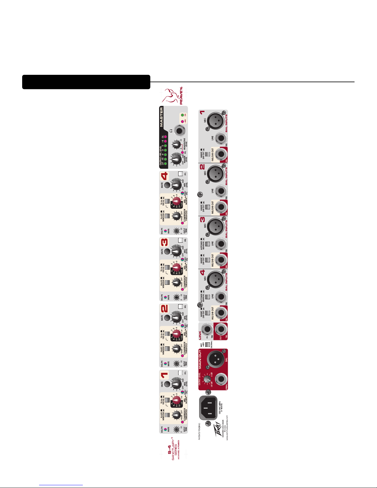
CHANNEL & MASTER FUNCTIONS
Page 6
6
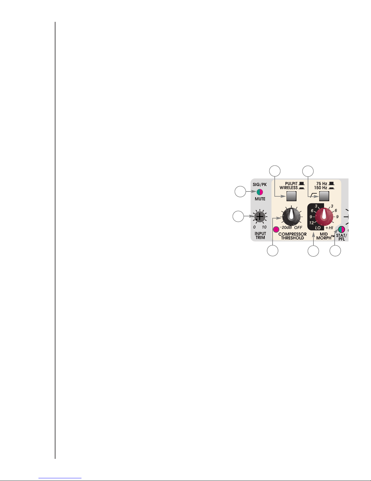
1. INPUT TRIM: This control adjusts the gain of the input preamplifier, which sets the operating level for the channel.
We recommend that the gain be adjusted so that ringing does not occur with the channel’s mix level control
set to maximum. The signal present LED (green) should be lit most of the time and the clip LED (red) should
never light. If the channel mix control is typically below the 12 o'clock position, the gain can be lowered
further to make mix adjustments simpler. The channel level can be checked by engaging the PFL button and
observing the signal on the meter and in the headphones. This control can be adjusted with your fingers but
is recessed to prevent accidental adjustment.
2. SIGNAL/MUTE/CLIP LED: This light tells three stories. It illuminates green when the channel signal level exceeds
–20 dBu, giving a quick visual indication that audio is present in the channel. If the signal level nears the
overload point, it flashes red, warning that gain should be reduced. If the mute switch is pressed, it lights red
continuously to indicate that the channel is off.
3. WIRELESS/PULPIT PRIORITY ASSIGNMENT: When a person speaks into a mic connected to the S-4, the
Automix
™
circuitry reduces gain of other channels with lower signal levels. If the signal level is the same on
two channels, each channel gets the same gain if their priority is the same. However, when a person wearing
a wireless microphone walks near another microphone that is on, the resulting interference, called comb
filtering, can hinder intelligibility and cause distraction. Setting this switch to the wireless position (high
priority) gives the channel dominance over pulpit priority
inputs and wireless priority inputs with a lower signal
level. (A wireless microphone should have precedence
over a fixed podium microphone to reduce the comb
filtering effects that occur when both pick up the same
source.) For applications such as meetings and panel
discussions, the moderator or main speaker can have
priority even if he/she is not using a wireless microphone.
4. 75 Hz/150 Hz LOW-CUT FILTER: The low-cut filter switch
selects 75 Hz or 150 Hz for the low cut filter frequency.
The filter slope was intentionally chosen to be 12
dB/octave so it can also be used for equalization. This filter
can help reduce microphone stand and handling noise and
also reduce the proximity effect.
5. COMPRESSOR THRESHOLD: Each channel has a built-in soft-knee compressor to help keep loud voices from
getting out of control. This control sets the point where compression begins. When the amount of gain
reduction exceeds 3 dB, the red LED beside it illuminates. To set this control, begin at the maximum position
and turn it counterclockwise to the point where the LED lights only on loud peaks. If the LED blinks most
of the time, the threshold should be raised. If compression is not required, set this control to maximum (off).
6. Mid Morph
™
EQ: Where most midrange controls work at just one frequency, Mid Morph works at two. When
turned counterclockwise, it reduces the volume of low/mid frequencies to reduce muddiness. When turned
clockwise, it boosts high/mid frequencies to add intelligibility to vocals. Either way, improved vocal or
instrument definition can be achieved.
7. STATUS/PFL: This light is green when the channel is active and is a dominant Automix channel. It will also light green
if the channel is in manual mode. If it is not lit, it does not mean that the channel is off, but that the level is
being attenuated. The light will change color to red when the PFL switch is pressed, showing that this channel
has been assigned to the PFL monitoring bus.
1
2
3
4
5
6
7
Page 7

7
8. MIX LEVEL: This control adjusts the level of the channel in the main output. It is a
part of the Automix™circuitry and affects priority and sharing ratios. It is
recommended that the gain be set to keep this control between 12 o’clock and full
clockwise. The system is calibrated with this control set fully clockwise.
9. MUTE: This control mutes the channel in the main and direct outputs and removes
the signal from the Automix computer. The Signal/Pk/Mute LED lights red to indicate
that the channel is off.
10. PFL: PFL is an acronym for Pre-Fader Listen. When pressed, this switch sends the
channel signal (picked up before the mix level control) to the headphone circuitry and
output meter for monitoring. This is useful in setting input gain and EQ, pre-checking that the mic is working
and confirming who is speaking on that channel when things get out of control. (Not that it ever happens!)
11. OUTPUT/PFL METER: The output meter array indicates the main output signal level. With the back panel output
control set to 0, this corresponds to +4 dBu at the output connectors. When PFL is active, this meter shows
the level of that channel, and the PFL LED in the
master section lights to indicate that the
headphones and meter are monitoring an input.
12. HEADPHONE OUTPUT: This stereo jack (TRS)
drives the headphones. The level is set by the
headphone level control. Tip=Left, Ring=Right,
Shield=Ground.
13. HEADPHONE LEVEL: This control sets the
headphone volume. The headphone output
normally monitors the main S-4
™
output. If a PFL
button is activated, the PFL LED illuminates and
the headphone output and meter switch to the
PFL bus.
14. +48V LED: Lights to indicate that the phantom mic
supply is on.
15. MIC INPUT: XLR balanced microphone with phantom power.
Because of the wide range of gain adjustment, signal levels from –68
dBu to +22 dBu can be accommodated.
16. LINE INPUT: 1/4" balanced (TRS) 10k Ohm impedance input
can be used with balanced or unbalanced sources. It has 20 dB less
gain than the XLR input and does not have phantom power available.
The mic and line inputs should not be used simultaneously.
17. INS/DIR: This 1/4" jack is switch selected to function as either a
channel insert or a direct output connector. When the selector
switch is set to DIR position, the unbalanced output signal is post
EQ, post fader and post Automix. One application of this output is
for the user who wishes to maintain the other mix console but bring
each microphone up on its own fader. When the switch is in the
insert position, the jack serves as a TRS insert jack allowing signal processing, such as EQ, to be inserted into
the input signal chain. The insert jack is wired as: Tip=Send, Ring=Return, Sleeve=Ground and is post lowcut filter. When set to direct out the jack is wired as: Tip=Out, Ring=No Connection, Sleeve=Ground.
18. INSERT/DIRECT OUT SWITCH: This switch changes the function of the INS/DIR from direct out to channel
insert.
19. AUTOMIX/MANUAL SWITCH: Channels 3 and 4 can be removed from the Automix system. When set to manual,
the channel functions as a normal input channel but still has the advantage of the built-in compressor. When
the S-4s are used as the main sound system mixer, manual inputs can be used for music sources.
8
9
10
11
12
13
14
15
16
17
18 19
Page 8

8
20. MAIN OUTPUT LEVEL: This back panel control is an attenuator on the main XLR and 1/4" outputs. It is provided
to match the nominal operating levels of the S-4™to the inputs of either a mixing console, power amplifier
or recording device. It has a 30 dB attenuation range, allowing it to adjust from line to microphone levels as
required.
21. MAIN OUTPUTS (XLR and 1/4"): These independent, 1/4" unbalanced and XLR balanced outputs have their level
set by the master level control and the rear panel trim control. The nominal levels are +4dBu with the
output trim set to 0.
NOTE: Pin 1 of the XLR output connector is connected to chassis ground using a resistor-capacitor network to
minimize the chance of ground loops when connected to the main sound system.
22. LINK IN and LINK OUT: These TRS 1/4" jacks are used to interconnect S-4 mixers when additional inputs are
required. A single TRS-TRS shielded cable connected between the link out of the first S-4 and the link in of
the next S-4 ties together audio and control signals. Up to 10 units can be slaved together using this system.
When the S-4s are linked, the same audio signal appears at each S-4 output. The front panel master level
and rear panel output level controls only affect the signal level from that S-4’s output.
NOTE: The S-4's are NOT connected in a ring. The link in jack of the first and the link out jack of the last
S-4 mixers must be empty.
23. MIC +48V: A rear panel switch applies 48 Volt phantom power to the input XLR connectors for powering
microphones that require it. If phantom power is used, do not connect unbalanced dynamic microphones
or other devices to the XLR inputs that cannot handle this voltage. An LED on the front panel indicates that
phantom power is on. Phantom power is not applied to the 1/4" line inputs.
24. AC MAINS INPUT: Connect the line cord to this connector to provide power to the unit. Damage to the
equipment may result if improper line voltage is used. Operate only with the specified AC input voltage
applied.
U.S DOMESTIC AC MAINS CORD
The mains cord supplied with the unit is a heavyduty, three-conductor type with a conventional 120 VAC plug with
ground pin. If the outlet used does not have a ground pin, a suitable grounding adapter should be used and the third
wire should be grounded properly.
Never break off the ground pin on any equipment. It is provided for your safety.
20
21
22
23
24
Page 9

9
The S-4™is a versatile mixer with features that allow it to be used in many applications and connected in many ways.
It is difficult to cover all applications here, but four different schemes are detailed below. Read through the suggested
methods and determine what best fits your needs. If you have two or more S-4 mixers linked, designate one as the
master unit and use its output connectors and controls.
Main sound system mixer:
The S-4 (or linked S-4s) makes an excellent main mixer for applications where minimal adjustments or hands-off
operation is required. The Automix
™
circuitry and compressor allow the S-4 to be set and left unattended in many
applications. The S-4’s versatile EQ provides all of the tone adjustment necessary in most cases. Setting a channel to
manual mode configures it for music. Connect the S-4 balanced XLR output (preferred) or unbalanced 1/4" output
to the main sound system input.
SETUP AND APPLICATION
Choir Mics
Wireless Mic
Wireless Mic
out
out
link
n
i
Pulpit
Monitor System
Solo Mics
Main (House) System
Page 10

10
Sub-mixer:
Existing sound systems can also benefit from Automix™technology by the addition of one or more S-4™automatic
mixers. The Automix feature increases the available microphone gain, reduces background noise and virtually
eliminates comb-filtering on spoken word microphones. Spoken word microphones premixed by the S-4 are sent to
one input on the existing mix console. The S-4(s) should be conveniently mounted so their front panel controls can
be operated as needed. Not only does this add the power of automatic mixing to your existing system, but it also
frees additional input channels for music. Connect your spoken word microphones to the S-4 and its balanced XLR
output (preferred) or unbalanced 1/4" output to a mix console input.
Mix Console
House (Main)
System
Pulpit
Wireless Mic
Wireless Mic
Page 11

11
Automix™controller (console with post-fader direct outputs):
If you want to add the power of automixing but still want the microphones with their own faders on your existing
console, there are two approaches that can be used.
The best Automix "controller" approach requires post-fader channel direct outputs on your mix console. Connect
the mics to the console inputs, then send the console direct outputs to the line inputs on the S-4
™
(do not assign the
console inputs to a bus). The S-4 output is then connected to the console via a return or line input. Connecting the
S-4 in this fashion allows adjustments made on the console channel to be seen by the Automix computer.
Pulpit
Wireless Mic
Wireless Mic
4
3
2
1
Monitor
Mains
S-4 Output to
Console Line Input
Mixer with Post-Fader
Direct Output
3
4
2
(1-4) Console Channel
Direct Output to S-4 Line Inputs
1
Page 12

12
Wireless Mic
Automix™controller (using S-4™direct outputs):
If console direct outputs are not available, an alternate approach can be used. Connect the direct outputs of the
S-4 to the console line inputs. This approach gains most of the Automix advantages but has some potential
weaknesses that need to be addressed. Channels should be muted using the S-4 mute switches (not the
console’s mutes) so that the signal is removed from the S-4 Automix gain computer. The console channel gain
should be carefully set so that all Automix channels are the same. Big gain adjustments made at the console are
not seen by the S-4 but can affect the Automix. With that warning, if care is taken, this approach can work well.
Mount the S-4(s) so the mix engineer has easy access to its controls.
Pulpit
Mix Console
Wireless Mic
House (Main)
System
Page 13

To get proper performance (low noise and distortion) from the S-4™mixer and your sound system, the gain controls
throughout the chain must be properly adjusted. There are two basic parts to this process: setting the S-4 operating
levels and the operating levels of the mix console or sound system. The S-4 channel gain controls should be adjusted
so that the output meter reads 0 during normal use with the channel and master controls set at 0 (maximum). The
back panel output level control and the mix console or sound system input controls are then adjusted for proper level
in the room.
NOTE! An assistant will be required for most of the following adjustments. It will be assumed that whenever a microphone is
tested, the assistant is speaking into the microphone at a level typical of actual use.
Preparation
For all applications, except when used as an Automix
™
controller using the console direct outputs, start by:
Connecting the microphones to the S-4 inputs.
Set all channel gains to minimum.
Set channel mix level to 0 (maximum).
Set the Mid Morph
™
EQ to 0.
Set the low-cut filter to 75 Hz.
Set the master level to 0 (maximum).
Set the rear panel output level to –30 dB (minimum).
Mute all inputs except one that will be used for the initial setup.
With the assistant speaking at the un-muted microphone, increase the S-4 preamp gain until the output meter reaches
0. The S-4 is now adjusted for proper level on the first channel and can be used for next step.
Now the output of the S-4 must be calibrated to the sound system equipment. Use the procedure below that fits your
application.
Main sound system mixer
A. If you have not done so already, connect the S-4 output to the main sound system input. The preferred
connection is to use the XLR balanced output.
B. Increase the back panel output level control until either the sound level in the room is at moderate-loud level
or ringing is heard on the end of words. Adjust until ringing is not audible. (A sound contractor may wish to
set the back panel level control to 0 and use the sound system level controls to make this adjustment.)
C. Proceed to "Completing the Setup" (below).
Sound system submixer
A. If you have not done so already, connect the S-4 output to an input on your mix console. You might want to
consider using an input channel near the master controls where it will be easy to find if needed. The preferred
connection is to use the XLR balanced output, but an unbalanced 1/4" connection to the channel line input
can be used.
B. Set the console channel gain control to minimum and the channel fader to 0.
C. Increase the S-4 back panel output level control until either the sound level in the room is at a moderate-loud
level or ringing is heard on the end of words. Reduce the level until ringing is not audible. If you are connected
to a console line input and have turned the S-4 output level all the way up but have not reached the proper
level, then set the S-4 output level at 0 and increase the console’s channel gain to reach the proper level.
D. Proceed to "Completing the Setup" (below).
13
SETTING LEVELS
Page 14

14
Automix™controller using mix Console Direct outputs:
A. Connect your microphones to the mix console inputs.
B. Connect the corresponding mix-console, post-fader channel direct outputs to the
line inputs on the S-4
™
.
C. Set the S-4 gain controls to the unity gain position shown in figure 1.
D. Set the console’s fader to 0 (unity gain) and turn off all group (bus) assignments.
E. Adjust the console gain controls so that the S-4 output meter reads 0.
F. If you have not done so already, connect the S-4 output to an input or return on
your mix console. You might want to consider using an aux return input as you
will not want to adjust this control once it is set, but any line input can be used.
G. Increase the S-4 back panel output level control until either the sound level in the room is at moderate-loud
level or ringing is heard on the end of words. Reduce the level until ringing is not audible. If you are connected
to a console line input and have turned the S-4 output level all the way up but have not reached the proper
level, then set the S-4 output level at 0 and increase the console’s channel gain to reach the proper level.
H. Proceed to "Completing the Setup" (below).
Automix controller using the S-4 Direct outputs:
A. Set the rear panel switches to direct out (switch in).
B. Connect the direct outputs (unbalanced) to the console inputs using TS 1/4" cables.
C. Set the console channel fader to 0.
D. Adjust the console channel gain control for proper level in the room without ringing.
E. Proceed to "Completing the Setup" (below).
Completing the setup
A. Unmute one channel at a time and adjust its gain for a nice level in the room.
B. Adjust the Mid Morph
™
control for a natural sound quality.
C. Set the low cut filter frequency as needed to suppress handling noise, low rumble or excess bass due to close
proximity of sound source to the microphone. This is a 12 dB/octave filter so do not be afraid to use the 150
Hz setting if it improves the sound.
D. Set the mix level control at 0, and readjust the gain so that the microphone is just below ringing. In operation, if
you have to reduce the mix level control below the 12:00 position to get the desired volume at normal
speaking levels, set the level control at 12:00 and reduce the gain until the desired level is achieved.
Note: if you are using the S-4 as an Automix controller, leave the mix level controls at 0.
E. Adjust the compression threshold control counterclockwise so that the red compression LED only "blinks on" when
the person speaking starts getting loud. This can help control the volume of loud speakers. However, if the
threshold is set too low, (the LED is on much of the time) the volume will be unnecessarily limited and
feedback can be the result.
F. Repeat steps A-E for each microphone.
Fig. 1
Unity Gain Position
Page 15

15
GLOSSARY
Gain ➧ Amplification of an audio signal. A negative gain (in dB) is an attenuation or reduction of level of the signal.
Ringing ➧ The resonance (“ringing”) sounds heard (often at the end of words) when the sound system is close to acoustic
feedback.
Gain before feedback ➧ How much you can increase the gain of a mic (turn it up) before feedback occurs. You have
sufficient “gain before feedback” if you can turn up the gain on a mic and get acceptable volume with getting feedback or
ringing.
Directional mic ➧ A mic that picks up sound better from one direction than other. Cardioid mics are an example. They
pick up well from the front, slightly less from the sides and very little from the rear. This can be used to advantage by
reducing the pickup of sound from monitor or sound system speakers. (It only works though if the back of the mic (end
with the cord in most cases) is pointed at the speaker. When a singer bends down and points the front of the mic at the
monitor speaker, only the Feedback Ferret
®
or the channel mute can prevent feedback.
Compressor ➧ A audio compressor reduces the dynamic range of an signal by reducing (compressing) the gain when the
signal gets loud. The threshold control sets the point above which compression takes place.
Dynamic Range ➧ Dynamic Range describes the variation from soft to loud speech or music. Too wide a dynamic range
can result in sound that is difficult to hear when it is soft or perceived as too loud when loud. Sound with too little dynamic
range can be hard to listen to for long periods of time (the “elevator music” sound).
Expander ➧ An expander performs the opposite function of a compressor. It expands (widens) dynamic range. It is most
often used to turn down the sound from microphones when they are not in use.
Noise Reduction ➧ Background noise is reduced through use of automatic mixing circuitry and other circuitry that reduces
the gain of mics when not in use.
Auto-Level ➧ Automatic Level Control. This circuit reduces dynamic range so that the volume does not get too loud or
too soft. It increases the gain at low levels to reduce noise and compresses it at higher levels to control volume.
Feedback (Acoustic Feedback) ➧ Loud howling sound heard from the speaker system. It is caused by sound from the
speaker system reentering the microphone louder than the original sound. The sound keeps getting louder and we hear
what we know as acoustic feedback.
Comb Filter ➧ Although this sounds like a personal hygiene item, it actual refers to the frequency response that results
from combining two signals from one source where one is delayed. Although this may sound complicated, it occurs when
sound is picked up simultaneously by two mics that are slightly different distances from the sound source. As the source
(person) moves, you hear a sort of a swishing phasing sound. The priority feature on the automix helps prevent this
problem.
Foldback ➧ Sending sound back to the person speaking or performing so they can better hear themselves.
Fader ➧ The slide control on the mixer used to adjust the mix of microphone signals.
EQ (Equalization) ➧ Equalization is really a fancy word for tone controls that allow the user to equalize or emphasize/de-
emphasize the sound at certain frequencies.
Threshold ➧ On a compressor or expander, this is the signal level where the circuit starts working.
Page 16

16
S-4™Block Diagram
A
(CHAN 3 & 4 ONLY)
HEADPHONE OUT
PFL
PFL BUS
HP LEVEL
PFL-CNTRL
1
BALANCED
4
UNBALANCED
+48V POWER SUPPLY
PHANTOM POWER
+48V MIC
LINK OUT
21
MAIN OUT
OUTPUT/PFL
LINK IN
COMP
STATUS
PFL
2
MAIN BUS
MUTE
MIXING
AUTOMATIC
3
OUTPUT TRIM
MASTER VOLUMECOMP THRESH
AUTO/MAN
CIRCUITRY
PULPIT/WIRELESS
B
5-27-2004_11:1411
Date:
BLK_S4
P. O. Box 2898
of
Meridian, MS 39301
Peavey Electronics Corp.
Title:
Sheet Title:
Sheet
C
21
MIC
INSERT/DO
2
4
1
MUTE
LINE
INSERT/DO
HI PASS
+
-
PFL
CNTRL
75/150 HZ
GAIN
CHANNELS 1-4
B
LEVEL
MIDMPH
3
SIG/CLIP
+48V
(All automix)
A
Page 17

S-4
™
SPECIFICATIONS
17
Function
Input Z
(Ohms) Min
Input Gain Setting
Input Levels
Min** Nominal* Max
Bal /
Unbal
Connector
Input Specifications:
XLR Input
(150 Ohms)
2.2K Max Gain
(68 db)
Min Gain
(2 db)
-64 dBu
+2 dBu
-56 dBu
+10 dBu
-48 dBu
+22 dBu
Bal
XLR:
Pin 1 Gnd,
Pin 2 (+),
Pin 3 (-)
Line
(10K Ohms)
10K
Max Gain
(48 db)
Min Gain
(-18 db)
-44 dBu
+22 dBu
-36 dBu
+28 dBu
-28 dBu
>30 dBu
Bal
1/4" TRS Phone:
Tip (+),
Ring (-),
Sleeve Ground
** Min input level (Sensitivity) is the smallest signal that will produce nominal output (
+4 dBu) with channel and master faders set for
maximum gain
* Nominal settings are defined as the master level control set at maximum, and the channel mix level set at 50%, with the gain
adjustment pot as specified.
Function
Minimum
Load Z
(Ohms)
Output Level
Nominal Max
Bal /
Unbal
Connector
Output Specifications:
Main 600 +4 dBu
+22 dBu
+22 dBu
Unbal
Bal
1/4" Phone
XLR:
Pin 1 Gnd,
Pin 2 (+)
Pin 3 (-)
Headphone
8
None Specified
135 mW
(32 Ohms)
Unbal
1/4" TRS Phone:
Tip Left,
Ring Right
Sleeve Ground
0 dBu=0.775V (RMS) +4 dBu=1.23 (RMS)
Direct/Insert 600
+4 dBu +22 dBu
Unbal 1/4" Phone
Page 18

18
HHuumm && NNooiissee
OOuuttppuutt RReessiidduuaall NNooiissee SS//NN RRaattiioo ((RReeff.. ++44 ddBBuu)) TTeesstt CCoonnddiittiioonnss
Main -101 dBu 105 dB All level controls down
-88 dBu 92 dB Master level maximum,
Chan Mix levels at minimum,
All Channels Muted
-88 dBu 92 dB All level controls maximum, with input gain at minimum
(Hum & Noise measurements: 22 Hz to 22 kHz BW)
Gain:
Mic input Gain Adj Range: 2 dB to 68 dB
Mic input to Main output 68 dB (Max Gain)
Line input Gain Adj Range -18 dB to 48 dB
Line input to Main output 48 dB (Max Gain)
Frequency Response:
Mic Input to Main Output (with 75 HZ LC filter) 75Hz (-3 dB) to 55KHz (–1 dB)
Total Harmonic Distortion (THD):
0.05% 20Hz to 20KHz Mic to Main output (22 Hz - 22 KHz BW)
Equivalent Input Noise (EIN):
-129.8 dBu (Input terminated with 150 Ohms, maximum gain)
Crosstalk:
80 dB Adjacent Input Channels (20 Hz - 20 KHz)
Common Mode Rejection Ratio (Mic Input):
60dB min (20 Hz - 20 KHz)
70 dB typ @ 1 KHz
Meters: 7 position LED, peak reading.
(0 dB= +4 dBu)
Signal / Overload Indicators: Lights 2 dB below clipping
Dimensions: 19" W x 8.125" D x 1.75" H
Weight: 9 Lbs. 4.1 Kg
Power Requirements: 120VAC 60 Hz, 17 Watts
Page 19

19
PEAVEY ELECTRONICS CORPORATION LIMITED WARRANTY
Effective Date: July 1, 1998
WWhhaatt TThhiiss WWaarrrraannttyy CCoovveerrss
Your Peavey Warranty covers defects in material and workmanship in Peavey products purchased and serviced in the U.S.A. and Canada.
WWhhaatt TThhiiss WWaarrrraannttyy DDooeess NNoott CCoovveerr
The Warranty does not cover: (1) damage caused by accident, misuse, abuse, improper installation or operation, rental, product modification or neglect; (2)
damage occurring during shipment; (3) damage caused by repair or service performed by persons not authorized by Peavey; (4) products on which the serial
number has been altered, defaced or removed; (5) products not purchased from an Authorized Peavey Dealer.
WWhhoo TThhiiss WWaarrrraannttyy PPrrootteeccttss
This Warranty protects only the original retail purchaser of the product.
HHooww LLoonngg TThhiiss WWaarrrraannttyy LLaassttss
The Warranty begins on the date of purchase by the original retail purchaser. The duration of the Warranty is as follows:
Product Category Duration
Guitars/Basses, Amplifiers, Pre-Amplifiers, Mixers, Electronic
Crossovers and Equalizers 2 years *(+ 3 years)
Drums 2 years *(+ 1 year)
Enclosures 3 years *(+ 2 years)
Digital Effect Devices and Keyboard and MIDI Controllers 1 year *(+ 1 year)
Microphones 2 years
Speaker Components (incl. speakers, baskets, drivers,
diaphragm replacement kits and passive crossovers)
and all Accessories 1 year
Tubes and Meters 90 days
[*Denotes additional warranty period applicable if optional Warranty Registration Card is completed and returned to Peavey by original retail purchaser within 90 days of purchase.]
WWhhaatt PPeeaavveeyy WWiillll DDoo
We will repair or replace (at Peavey's discretion) products covered by warranty at no charge for labor or materials. If the product or component must be shipped to
Peavey for warranty service, the consumer must pay initial shipping charges. If the repairs are covered by warranty, Peavey will pay the return shipping charges.
HHooww TToo GGeett WWaarrrraannttyy SSeerrvviiccee
((11))
Take the defective item and your sales receipt or other proof of date of purchase to your Authorized Peavey Dealer or Authorized Peavey Service Center.
OR
((22))
Ship the defective item, prepaid, to Peavey Electronics Corporation, International Service Center, 412 Highway 11 & 80 East, Meridian, MS 39301 or Peavey
Canada Ltd., 95 Shields Court, Markham, Ontario, Canada L3R 9T5. Include a detailed description of the problem, together with a copy of your sales receipt or
other proof of date of purchase as evidence of warranty coverage. Also provide a complete return address.
LLiimmiittaattiioonn ooff IImmpplliieedd WWaarrrraannttiieess
ANY IMPLIED WARRANTIES, INCLUDING WARRANTIES OF MERCHANTABILITY AND FITNESS FOR A PARTICULAR PURPOSE, ARE LIMITED IN DURATION TO THE
LENGTH OF THIS WARRANTY.
Some states do not allow limitations on how long an implied warranty lasts, so the above limitation may not apply to you.
EExxcclluussiioonnss ooff DDaammaaggeess
PEAVEY'S LIABILITY FOR ANY DEFECTIVE PRODUCT IS LIMITED TO THE REPAIR OR REPLACEMENT OF THE PRODUCT, AT PEAVEY'S OPTION. IF WE ELECT TO
REPLACE THE PRODUCT, THE REPLACEMENT MAY BE A RECONDITIONED UNIT. PEAVEY SHALL NOT BE LIABLE FOR DAMAGES BASED ON INCONVENIENCE, LOS S OF
USE, LOST PROFITS, LOST SAVINGS, DAMAGE TO ANY OTHER EQUIPMENT OR OTHER ITEMS AT THE SITE OF USE, OR ANY OTHER DAMAGES WHETHER INCIDENTAL,
CONSEQUENTIAL OR OTHERWISE, EVEN IF PEAVEY HAS BEEN ADVISED OF THE POSSIBILITY OF SUCH DAMAGES.
Some states do not allow the exclusion or limitation of incidental or consequential damages, so the above limitation or exclusion may not apply to you.
This Warranty gives you specific legal rights, and you may also have other rights which vary from state to state.
If you have any questions about this warranty or service received or if you need assistance in locating an Authorized Service Center, please contact the Peavey
International Service Center at (601) 483-5365 / Peavey Canada Ltd. at (905) 475-2578.
Features and specifications subject to change without notice.
Page 20

Features and specifications subject to change without notice.
Peavey Electronics Corporation • 711 A Street • Meridian • MS • 39301
(601) 483-5365 • FAX (601) 486-1278 • www.sanctuary-series.com
80305173
©2004 Printed in the U.S.A. 5/04
 Loading...