

Page 1

RQ 200
Six Channel Mini Console
™
Operating Guide
Page 2
Intended to alert the user to the presence of uninsulated Òdangerous voltageÓ within the productÕs
enclosure that may be of sufficient magnitude to constitute a risk of electric shock to persons.
Intended to alert the user of the presence of important operating and maintenance (servicing)
instructions in the literature accompanying the product.
CAUTION: Risk of electrical shock Ñ DO NOT OPEN!
CAUTION: To reduce the risk of electric shock, do not remove cover. No user serviceable parts inside. Refer
servicing to qualified service personnel.
WARNING: To prevent electrical shock or fire hazard, do not expose this appliance to rain or moisture. Before using
this appliance, read the operating guide for further warnings.
Este s’mbolo tiene el prop—sito, de alertar al usuario de la presencia de Ò(voltaje) peligrosoÓ que no tiene
aislamiento dentro de la caja del producto que puede tener una magnitud suficiente como para constituir
riesgo de corrientazo.
Este s’mbolo tiene el prop—sito de alertar al usario de la presencia de instruccones importantes sobre la
operaci—n y mantenimiento en la literatura que viene con el producto.
PRECAUCION: Riesgo de corrientazo Ñ ÁNo abra!
PRECAUCION: Para disminu’r el riesgo de corrientazo, no abra la cubierta. No hay piezas adentro que el usario
pueda reparar. Deje todo mantenimiento a los tŽcnicos calificados.
ADVERTENCIA: Para evitar corrientazos o peligro de incendio, no deje expuesto a la lluvia o humedad este aparato
Antes de usar este aparato, Iea m‡s advertencias en la gu’a de operaci—n.
Ce symbole est utilisŽ pour indiquer ˆ lÕutilisateur la prŽsence ˆ lÕintŽrieur de ce produit de tension nonisolŽe dangereuse pouvant •tre dÕintensitŽ suffisante pour constituer un risque de choc Žlectrique.
Ce symbole est utilisŽ pour indiquer ˆ lÕutilisateur quÕil ou quÕelle trouvera dÕimportantes instructions sur lÕutilisation et lÕentretien (service) de lÕappareil dans la littŽrature accompagnant le produit.
ATTENTION: Risques de choc Žlectrique Ñ NE PAS OUVRIR!
ATTENTION: Afin de rŽduire le risque de choc Žlectrique, ne pas enlever le couvercle. Il ne se trouve ˆ lÕintŽrieur
aucune pi•ce pouvant •tre reparŽe par lÕutilisateur. Confier IÕentretien ˆ un personnel qualifiŽ.
AVERTISSEMENT: Afin de prŽvenir les risques de dŽcharge Žlectrique ou de feu, nÕexposez pas cet appareil ˆ la
pluie ou ˆ lÕhumiditŽ. Avant dÕutiliser cet appareil, lisez les avertissements supplŽmentaires situŽs dans le guide.
Dieses Symbol soll den Anwender vor unisolierten gefŠhrlichen Spannungen innerhalb des GehŠuses warnen, die von Ausreichender StŠrke sind, um einen elektrischen Schlag verursachen zu kšnnen.
Dieses Symbol soll den Benutzer auf wichtige Instruktionen in der Bedienungsanleitung aufmerksam
machen, die Handhabung und Wartung des Produkts betreffen.
VORSICHT: Risiko Ñ Elektrischer Schlag! Nicht šffnen!
VORSICHT: Um das Risiko eines elektrischen Schlages zu vermeiden, nicht die Abdeckung enfernen. Es befinden
sich keine Teile darin, die vom Anwender repariert werden kšnnten. Reparaturen nur von qualifiziertem Fachpersonal
durchfŸhren lassen.
ACHTUNG: Um einen elektrischen Schlag oder Feuergefahr zu vermeiden, sollte dieses GerŠt nicht dem Regen oder
Feuchtigkeit ausgesetzt werden. Vor Inbetriebnahme unbedingt die Bedienungsanleitung lesen.
2
Page 3

ENGLISH
RQª200 Compact Console
GENERAL DESCRIPTION:
The RQª200 is a compact mixer that can be used in sound reinforcement or recording
applications. Its external AC adapter/internal DC battery power option allows great portability. Low
noise design and an extensive feature list make the RQª200 the perfect mixing console for almost
any portable application, including remote audio to video recording/editing.
CHANNELS:
This console has two mono and four stereo input channels, with a total of 14 inputs available
at mixdown. Both mono inputs feature discrete transistor low noise mic preamps and line inputs with
insert jacks, two-band equalization, effects and monitor sends.
Channels 3 thru 5 add stereo line inputs to the features of Channels 1 and 2. The stereo
inputs utilize a separate level control which allow them to be used with the mic input of the same
channel simultaneously.
Channel 6 is set up to accommodate those stereo devices that are not typical to standard
sound reinforcement applications. Featuring a selection of stereo RCA and 3.5mm stereo jacks at
the line input, the RQª200 reduces the need for costly adapters that always seem to get left behind.
MASTER:
The Master section includes a left/right fader, headphone output (both 1/4" and 3.5mm), a
headphone output control and a 5-segment stereo level meter to observe output levels. In addition,
the RQª 200 includes master controls for the effects and the monitor sends. Phantom power is also
available via the switch located in the Master section.
OUTPUTS:
The RQ
ª
200 has four outputs: Left and Right Main, Monitor Send, and Effects Send. The
Left and Right outputs for the main signal can be accessed via one of three different pair of output
jacks. For convenience stereo 1/4" (TRS) balanced jacks, stereo RCA jacks, and a stereo 3.5mm
jack are provided to offer either balanced or unbalanced signal transfer.
This manual includes a detailed description of each feature and its function within the
RQª200. Following the description you will find application notes which better describe the typical
utilization of these features. Please read these sections carefully and take note of the warnings
throughout. Congratulations on your purchase of the RQª200 mixing console.....enjoy!
3
Page 4
CHANNEL FUNCTIONS:
The Following applies to Channels 1-6:
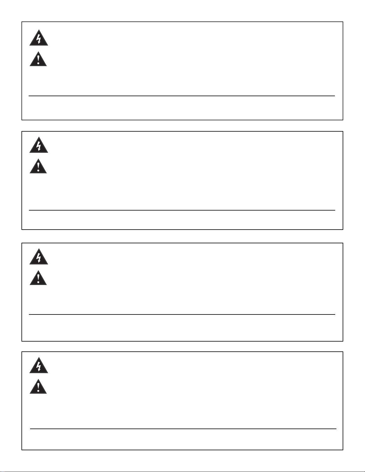
1. MIC INPUT: XLR balanced low impedance channel input
optimized for a microphone or other low impedance source.
Pin 2 is the positive input. Because of the wide range of gain
adjustment, signal levels up to +5 dBu (1.3 V RMS) can be
accommodated.
2. MIC GAIN: Varies the input gain to allow for a wide dynamic
range. It affects both the line and mic inputs on Channels 1 and
2. Channels 3-6 have separate gain controls for Line and Mic
inputs (see #1 and 10). Proper adjustment of the input gain
through use of the LED level meter will maximize the signal-tonoise ratio. Application note #9 on page 8 explains this simple
method in detail.
3. PAN: Sets the channelÕs position in the L/R fields. For stereo
channels (3, 4, 5 and 6), the Pan also acts as a balance control.
As one field is increased the other is decreased. For instance,
increasing the left signal (turning the knob counter-clockwise)
will result in a decrease of the right signal.
4. HI EQ: A shelving type of active tone control that varies the
treble frequency levels +/-15 dB at 10 kHz. It is designed to
remove noise or to add brilliance to the signal, depending on
the quality of the source.
5. LOW EQ: A shelving type of active tone control that varies
the bass frequency levels +/-15 dB at 70 Hz. It will add depth to
thin signals, or clean up muddy ones.
6. MON: Adjusts the level of the channel signal (pre-EQ) that is
added to the monitor mix. This is a mono mix of the left and
right signals in the stereo channels. The center detent is the
unity gain position.
7. EFX: Adjusts the level of the channel signal (post-EQ) that is
added to the effects bus. This is a mono mix of the left and right
signals.
8. FADER: Channel output level control. The level of the
channel can be adjusted from off to +10 dB of gain. The
optimum setting is the Ò0Ó (unity gain) position.
Channels 1-2 feature the following:
9. INSERT: 1/4" stereo (TRS) jack which allows an external
device to be inserted into the signal path before the tone equalization. The tip has the send signal; the ring is the return input.
A switch in the jack normally connects the send to the return
until a plug is inserted. By plugging in part way (first click), the
jack can be used as a preamp output without interrupting the
channel.
10. LINE INPUT: 1/4" balanced (TRS) high impedance input for
high level signals. The tip is the positive input, which should
also be used for unbalanced inputs. This input is connected
through a 20 dB pad to the MIC input (# 1). The two inputs cannot be used simultaneously.
4
1
2
4
5
6
7
8
10
3
9
Page 5
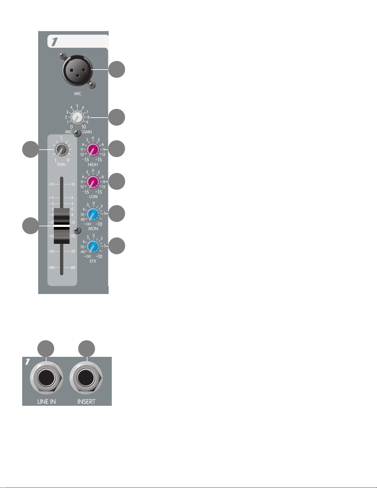
Channels 3-5 feature the following:
11. Left/Mono Input: High impedance input for line-level signals.The
left/mono input supplies signal to both the left and right inputs (if there is
nothing inserted in the right input jack). This input is controlled by the Line
Gain and Pan controls as well as the High/Low EQ and Fader controls.
12. Right Input: High impedance input for line-level signals. The Right Input
supplies signal to the the channelÕs right bus and is controlled by the Line
Gain and Pan controls as well as the High/Low EQ and Fader controls.
13. Line Gain: Varies the gain of the Line Input to allow for a wide dynamic
range. Adjusting this input gain properly will maximize the signal-to-noise ratio.
Remember that this control will not control a signal from the Mic Input.
5
12
11
Channel 6 features the following:
14. RCA Stereo Inputs: The Left and Right Inputs (RCA) are identical to the
Left and Right Inputs found on Channels 3-5. The RCA inputs, however, do not
feature the mono switching function. Each jack (L and R) remains operative at
all times.
15. 3.5mm Stereo Inputs: These inputs are wired in parallel to the RCA Stereo
Inputs and share the exact functions.
OUTPUTS
16. Main Out: The Main Output of the RQª 200 offers three different types (RCA, 3.5mm, and 1/4")
of stereo audio output sources. This is intended to give you the flexibility for any application and to
eliminate the need for adapters. The 1/4" jacks are standard TRS connector which can be used in
either balanced or unbalanced applications.
SENDS
17. Monitor Send: This 1/4" mono jack provides an output for the Monitor bus. The level of the
signal is controlled by the Monitor Master control as well as the individual channel Monitor controls.
18. Effects Send: This 1/4" mono jack provides an output for the Effects bus. The level of the
signal is controlled by the Effects Master and the individual channel Effects controls.
HEADPHONE
19. 1/4" Stereo Headphone Output: This stereo jack (TRS) provides the signal to
drive stereo headphones. The level is set by the headphone level
control. Tip= Left, Ring= Right, Shield= Ground.
20. 3.5mm Stereo Headphone Output: 3.5mm stereo jack wired
in parallel to the 1/4" Stereo Headphone Output jack providing an
alternate headphone output for smaller type headphone sets.
20
19
16
17
18
13
15
14
Page 6
6
Plugging into the 1/4" headphone output disconnects the 3.5mm headphone output. In applications where the RQª200 is used for computerbased recording, this jack makes an ideal input to powered speakers.
Application note #10 on page 8 describes this process in more detail.
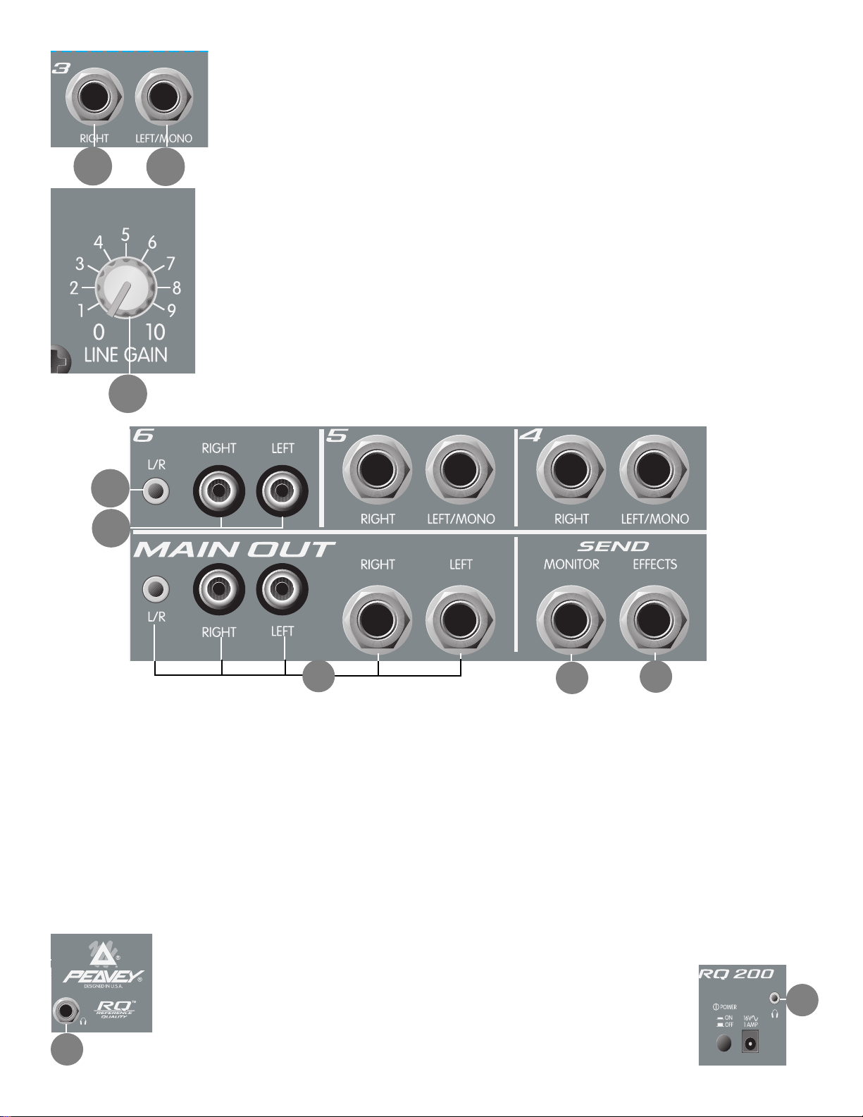
MASTER SECTION
21. Master Left/Right Fader: Master L/R level control. Since the main sig-
nal comes from this mix, all main outputs (16) will be affected by its adjustment. The output levels are monitored by the left and right meters. The
optimum setting for this control is the Ò0Ó (unity gain) position.
22. Headphone Level: Adjusts the level of the headphone outputs.
23. Effects Master: Controls the level of the Effects signal found at the
Effects Send jack.
24. Monitor Master: Controls the overall level of the Monitor mix found at
the Monitor Send jack.
25. LED Meters: Two 5-segment LED arrays monitor the levels of the
main L/R outputs. The 0 dB reference level corresponds to +0 dBu at the
1/4" jacks. The Clip LED at the top of each array illuminates when the
signal is either clipping or is within 2 dB of clipping.
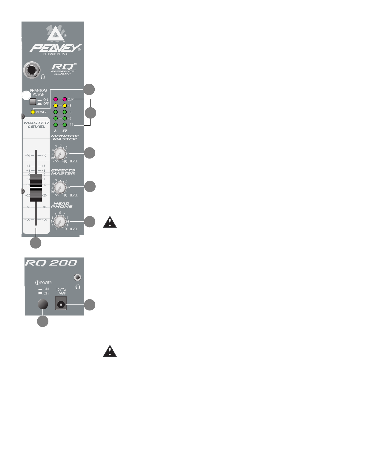
POWER
26. AC Input: The external 16.5 volt, 1 amp power supply should be
plugged in at this jack. Plug the small barrel connector of the supply
into the RQ
ª
200 and plug the power supply into a main AC power
receptacle which provides the proper line voltage as indicated on the power
supply casing.
27. Power: The mixerÕs main power switch. Pressing the switch in will
provide power to the RQª200. The Power LED indicator will light when the
unit is powered.
28. Power LED: Illuminates to indicate that the RQª200 is powered up.
29. Phantom Power: Applies 22 VDC voltage to the input XLR
connectors to power microphones that require it. If phantom power is used,
do not connect unbalanced dynamic microphones or other devices to the
XLR inputs that cannot handle this voltage. (Some wireless receivers
may be damaged; consult their manuals.) The line input jacks are not
connected to the 22 V supply, and are safe for all inputs (balanced or
unbalanced).
NOTE: When the RQª200 is being powered by battery,
the Phantom Power is 8 VDC. However, additional battery positions
are provided in the battery compartment so extra cells may be added to
provide 17 VDC. See Battery Compartment #30 for more information.
29
28
25
24
23
22
21
27
26
Page 7
30. Battery Compartment:
Located underneath the RQ 200 is the battery compartment. Removing the compartment door
reveals the two 9V battery positions as well as the optional phantom power battery position. Placing
a third 9V battery in the phantom position (see diagram below) will increase the phantom power
from 8 VDC to 17 VDC. See Phantom Power, #29, for more information. Always use 9V alkaline
batteries.
APPLICATION NOTES
1. Microphones and other low impedance sources should be connected to the XLR mic inputs;
high level line inputs, such as electronic musical instruments, should be connected to the line
inputs. Stereo line level sources (synth, tape, CD, camera audio, etc.) should be connected to
one of the stereo channels, or to two of the mono line inputs (one panned left, the other
panned right).
2. The house power amplifier inputs should be connected to the main Left and Right 1/4"
outputs using TRS to TRS (or TRS to XLR depending on amp inputs) for balanced
applications. If your power amp does not have balanced inputs, any of the Main Outputs
may be used.
3. Connect the monitor power amplifier input to the Monitor Output. If the Effects Output is not
being used, it can serve as a second Monitor Output (post-EQ).
4. If an effects device is used, connect its input to the Effects Output of the RQ
ª
200.
Remember to adjust the Effects Master to insure you are not clipping the input of the effects
device.
5. The effects device outputs are connected to one of the inputs on the RQª200. NOTE: It is
very important to turn the EFX knob to Ò0Ó on this input, channel in order to avoid a feedback loop.
6. Three different types of output jacks are provided: 1/4" stereo TRS (bal/unbal), stereo RCA
(unbalanced), and 3.5mm (unbalanced). Though it is possible to use all three outputs
simultaneously, it is not recommended due to the loading effects it may cause. Incidentally,
these outputs offer variety in order to cover most applications where a portable mixer is
needed to record audio to video, DAT, etc. in addition to sound reinforcement.
7
Ð +
Ð +
Ð +
*Phantom
Mixer
Mixer
*Optional for +17V Phantom Power
USE 9V ALKALINE BATTERIES
Page 8

8
7. The RQª200 offers two options for power. If AC power is readily available, it is recommended
to use a 16 VAC external supply. However, the RQª200 is equally capable using batteries.
Use only alkaline in the RQª200.
8. As is common practice, turn down all gain controls that are not being used to lessen noise.
For instance, if you are using only the left and right inputs of a stereo channel (and not the
Mic Input), turn the Mic Gain down completely to eliminate any gain noise from the unused
Mic Input.
9. To adjust input levels properly, begin with setting the channelÕs fader to Ò0Ó. Place the Master
Fader to Ò0Ó as well. With no other activity from adjacent channels, adjust the proper gain
control for the particular input you are working with. On the stereo channels (3-6) you will
want to make sure you are adjusting the Mic Gain for the Mic Input and the Line Gain for the
Line Input. Use the LED Meters to set your level just below clipping when your audio reaches
its peak points. Follow this practice for each channel.
10. When using the RQª200 for audio recording/editing via computer, there are three connections required for optimum benefit. First, connect the Main Output (3.5mm stereo jack) of the
RQª200 to the input of your sound card using the 3.5mm jack. Second, connect the output of
your sound card to the 3.5mm stereo input jack of Channel 6. Finally, connect the cable from
your powered speakers to the 3.5mm headphone output jack.
Using the 3.5mm headphone jack gives you an obscure function that is really convenient.
Just as a typical studio would offer the option of headphone or reference speaker monitoring,
you now have that same choice. While listening to your audio activity via your powered
speakers, you have the option at any time to plug a set of headphones into the other headphone jack. This jack, unlike the 3.5 mm, is a 1/4" stereo switching jack. By plugging into the
1/4" jack, you automatically disconnect the powered speakers and you can now listen to your
audio through headphones. ItÕs a great feature that youÕre sure to find very convenient.
Of course, both headphone output levels are controlled by the Headphone Master control at
the bottom, right-hand corner of the RQ
ª
200.
Page 9

9
RQª200 Mini Console
Specifications:
RQª200 Input Specifications:
Input Input Input Input Levels, dBu* Bal./ Connector
Imped. gain-pot Min.** Nominal Max.*** Unbal.
(Ohms) setting,
Min. dB
Microphone 2 k Max. Gain -72 -52 -34 Bal. XLR Pin:
Chan. 1-6 +52 dB -37 (bat.) Pin 1 (Ground)
Pin 2 (+)
Min. Gain -30 -10 +8 Pin 3 (-)
+10 dB +5 (bat.)
Line Input 20 k Max. Gain -52 -32 -14 Bal. 1/4" TRS:
Chan. 1 and 2 +32 dB -17 (bat.) Tip (+),
Ring (-)
Min Gain -10 +10 +30 Sleeve (Ground)
-10 dB
Stereo 8 k Max. Gain -36 -16 +2 Unbal. 1/4" TRS:
Line Input +16 dB -1 (bat.) Tip (+)
Chan. 3-5 Sleeve (Ground)
Nom. Gain -20 0 +18
0 dB +15 (bat.)
Stereo 8 k Max. Gain -36 -16 +2 RCA TS/
Line Input +16 dB -1 (bat.) Unbal. 3.5mm TRS:
Chan. 6 Tip (Left)
Nom. Gain -20 0 +18 Ring (Right)
0 dB +15 (bat.) Sleeve (Ground)
* 0 dBu = 0.775V (RMS)
** Minimum input level (Sensitivity) is the smallest signal that will produce nominal output with controls set for
maximum gain.
*** Maximum input signal that will cause clipping with controls set at nominal gain position
* 0 dBu = 0.775V (RMS)
(Bat.): Under battery power
Output Min. Load Output Level dBu* Bal./ Connector
Impedance Nom. Max. Unbal.
(Ohms)
0 +18 Unbal. 1/4" TRS:
Master L/R 600 +15 (bat.) Bal. TIP (Left)
Ring (Right)
+6 +24 Bal. Sleeve (Ground)
+21 (bat.)
600 0 +18 1/4" TS:
Monitor Send +15 (bat.) Unbal. Tip (+)
Sleeve (Ground)
600 0 +18 1/4" TS:
Effects Send -15 (bat.) Unbal. Tip (+)
Sleeve (Ground)
RQª200 Output Specifications:
Page 10

Gain:
Mic Input to Channel Insert Send:
Mic Input to Main Left/Right:
Mic Input to Monitor, Effects Send:
Line Input 1 and 2 to Main Left/Right:
Line Input 3 to 6 to Main Left/Right:
Variable +10 dB to +52 dB
72 dB
75 dB
52 dB
36 dB
Frequency Response:
Mic Input to Left Ñ Right Outputs:
Mic Input to Monitor Ñ Effects Outputs:
10 Hz to 30 kHz (+0, -1 dB)
10 Hz to 25 kHz (+0, -1 dB)
Total Harmonic Distortion (THD):
<0.01% Ñ 1 kHz, Mic Input to Left/Right outs @ nominal level (22 Hz to 22 kHz BW)
Hum and Noise:
EIN -128 dBu (Terminated 150 Ohms)
RQª200 SPECIFICATIONS:
Output S/N Ratio, dB Test Conditions
Ref. Nom. Out Level = 0 dBu
-97 All faders down
-82 Master fader nom./chan. fader/send down
Master L/R -80 All fader nom.: Min. gain
-62 All fader nom.: Max. gain
-102 Master down
Monitor and -80 Master nom./chan. down
Effects -76 Master/channel nom.: Min. gain
-58 Master/channel nom.: Max. gain
(Hum and Noise - with filter: 22 Hz ~ 22 kHz)
COMMON MODE REJECTION RATIO (C.M.R.R.):
Mic Input:
60 dB typical @ 1 kHz
Meters:
Five-segment peak-level meters (0 dB reading
corresponds to nominal output level: 0 dBu on the
unbalanced outputs, +6 dBu on the balanced outputs)
Phantom Power:
22 V typical with AC power
8 V with two - 9V batteries
17 V with 3
rd
phantom power battery
Dimensions (H x W x D):
3" x 13.875: x 10"
(7.6 cm x 35.2 cm x 25.4 cm)
POWER REQUIREMENTS:
AC Operation:
16.5 VAC, 1 amp 250 ma 4 watts
Provided from one of the following 16.5 VAC, 1 amp
power transformers:
100 VAC Primary - Peavey 70901112
120 VAC Primary - Peavey 70900660
230 VAC Primary - Peavey 70900862
Battery Operation:
¥ Two 9V Alkaline batteries for basic mixer operation with
8V Phantom power
¥ Three 9V Alkaline batteries for basic mixer operation
with 17V Phantom power
Weight:
5.5 pounds (2.5 kg)
10
Page 11

11
LEFT
RQ
ª
200 FLOWCHART
3.5mm
STEREO
RIGHT
MON
EFF
MAIN
SIGNAL BUS
METERLED
LEFT
1
EFF
MON
RIGHT
LEFT
1/4" TOP
56
S
3.5mm BACK
S
65
RCA
4
1
HEADPHONE
HEADPHONE
3
2
1
1
RIGHT
1
MON
EFF
HEADPHONE
1
4
3
2
HP LEVEL
EFF
PAN
PAN
MAIN
1 and 2
INPUTS
4
S
4
4
3
2 BAND EQ
+22 V
GAIN
4.9 V
4.9 V
MIC
INSERT
1
2
EFF
3
2
1
LOW HIGH
MON
LINE
GAIN
4.9 V
4.9 V
MIC
3 - 6
INPUTS
MIC GAIN
LEVEL
STEREO LINE
L/MONO
LOW HIGH
RIGHT
MON
LINE GAIN
INPUTS 3-5
R
L
INPUT 6 ONLY
LEFT
RIGHT
3.5mm
STEREO
Page 12

ESPAÑOL
Consola Compacta RQª200
DESCRIPCIîN GENERAL:
La consola mezcladora compacta RQª200 puede usarse en aplicaciones de refuerzo de
sonido o para grabaci—n. El adaptador de CA externo/bater’a de CC interna opcional proporcionan
una gran portabilidad. El dise–o de bajo nivel de ruido y la gran cantidad de funciones de la consola
mezcladora RQª200 la convierten en una unidad ideal para casi todas las aplicaciones port‡tiles,
como por ejemplo para grabaci—n y edici—n remotas de audio a video.
CANALES:
Esta consola tiene dos canales de entrada monoaurales y cuatro canales estereof—nicos, con
un total de 14 entradas disponibles para mezclas. Ambas entradas monoaurales est‡n equipadas
con preamplificadores de micr—fono de bajo nivel de ruido y transistores discretos, as’ como con
entradas de l’nea con enchufes hembra de inserci—n, ecualizaci—n de dos bandas y se–ales de
muestra de efectos y para monitoreo.
Adem‡s, los canales 3 a 5 incorporan entradas de l’nea estereof—nicas a las funciones de los
canales 1 y 2. Las entradas estereof—nicas utilizan un control de nivel independiente, lo que permite
usarlas simult‡neamente con la entrada de micr—fono correspondiente al mismo canal.
El canal 6 est‡ configurado para aceptar dispositivos estereof—nicos no habituales en las
aplicaciones convencionales de refuerzo de sonido. La consola mezcladora RQª200 presenta una
variedad de enchufes hembra estereof—nicos RCA y de 3,5 mm en la entrada de l’nea con el fin de
reducir la necesidad de usar costosos adaptadores que siempre parecen dejarse olvidados.
SECCIîN MAESTRA:
La secci—n MAESTRA comprende un atenuador izquierdo/derecho, una salida para
auriculares (tanto de 1/4 pulg. como de 3,5 mm), un control de salida de auriculares y un
medidor de nivel estereof—nico de 5 segmentos para observar los niveles de la salida. Adem‡s, la
consola RQ
ª
200 cuenta con controles maestros para las se–ales de muestra de efectos y para
monitoreo. La secci—n maestra tambiŽn dispone de un conmutador para alimentaci—n fantasma.
SALIDAS:
La consola mezcladora RQª200 tiene cuatro salidas: principales izquierda y derecha, se–al
de muestra para monitoreo y se–al de muestra de efectos. Puede accederse a las salidas izquierda
y derecha correspondientes a la se–al principal a travŽs de uno de los tres diferentes pares de
enchufes hembra de salida. Se dispone de enchufes hembra estereof—nicos balanceados (TRS) de
1/4 pulg., enchufes hembra RCA estereof—nicos y un enchufe estereof—nico de 3,5 mm para facilitar
la transferencia de se–al equilibrada o no equilibrada.
En este manual usted encontrar‡ una descripci—n detallada de cada caracter’stica y su
funci—n en la consola mezcladora RQª200. A continuaci—n de la descripci—n, podr‡ encontrar notas
de aplicaciones que describen en forma m‡s detallada el uso t’pico de esas funciones. Por favor,
lea estas secciones cuidadosamente y respete todas las advertencias. Felicitaciones por haber
comprado la consola mezcladora RQª200É Ádisfrœtela!
12
Page 13

13
Consulte los diagramas del panel delantero en
la secci—n de inglŽs de est manual.
FUNCIONES DE LOS CANALES:
La siguiente descripci—n se aplica a los canales 1 a 6:
1. ENTRADA DE MICRîFONO: Entrada de canal XLR equilibrada de baja impedancia, optimizada
para micr—fonos u otras fuentes de se–al de baja impedancia. El terminal 2 es la entrada positiva.
Debido a la gran amplitud del ajuste de la ganancia, esta entrada admite niveles de se–al hasta
+5 dBu (1,3 Vef).
2. GANANCIA DE MICRîFONO: Var’a la impedancia de entrada para lograr una amplia gama
din‡mica. Tiene efecto tanto sobre la entrada de l’nea como sobre las entradas para micr—fono de
los canales 1 y 2. Los canales 3 a 6 cuentan con controles de ganancia independientes para las
entradas de l’nea y micr—fonos (vea los nœmeros 1 y 10). El ajuste apropiado de la ganancia de
entrada por intermedio del medidor de nivel con indicadores LED aumenta al m‡ximo la relaci—n
se–al-ruido. En la nota 9 de la p‡gina 8 se explica detalladamente este sencillo mŽtodo.
3. BALANCE: Determina la posici—n del canal en los campos izquierdo y derecho. En el caso de
los canales estereof—nicos (3, 4, 5 y 6), este control tambiŽn tiene funciones de balance. Cuando se
aumenta el valor de un campo, se reduce el otro. Por ejemplo, si se aumenta la se–al izquierda (es
decir, se gira la perilla hacia la izquierda), la se–al derecha se reducir‡.
4. ECUALIZACIîN DE ALTOS: Control de tonos activo de tipo escal—n que modifica los niveles de
frecuencia de los sonidos agudos en ±15 dB a 10 kHz. Fue dise–ado para eliminar ruidos o agregar
claridad a la se–al, segœn la calidad de la fuente.
5. ECUALIZACIîN DE BAJOS: Control de tonos activo de tipo escal—n que modifica los niveles de
frecuencia de los sonidos graves en ±15 dB a 70 Hz. A–ade profundidad a las se–ales limpias o
limpia las sucias.
6. MON: Ajusta el nivel de la se–al del canal (antes de la ecualizaci—n) que se agrega a la
respectiva mezcla para monitoreo. ƒsta es una mezcla monof—nica de las se–ales de los canales
estereof—nicos izquierdo y derecho. La posici—n central es la de ganancia unitaria.
7. EFX: Ajusta el nivel de la se–al del canal (despuŽs de la ecualizaci—n) que se agrega al bus de
efectos especiales. Esta es una mezcla monof—nica de las se–ales de los canales izquierdo y
derecho.
8. ATENUADOR: Control de nivel de salida del canal. El nivel del canal puede ajustarse entre
apagado y +10 dB de ganancia. La configuraci—n —ptima de este control es la posici—n Ò0Ó
(ganancia unitaria).
Los canales 1 y 2 tienen las siguientes caracter’sticas:
9. INSERCIîN: Este enchufe estereof—nico hembra de 1/4 pulg. (TRS) permite conectar un
dispositivo externo en el circuito de la se–al antes del ecualizador de tono. La punta corresponde
a la se–al de muestra; el anillo es la entrada del retorno. Normalmente, el conmutador del enchufe
hembra permite conectar la se–al de muestra al retorno hasta que se conecta un enchufe macho.
Si se conecta parcialmente (hasta o’r el primer clic), el enchufe puede utilizarse como salida de
preamplificaci—n sin interrumpir el canal.
Page 14

10. ENTRADA DE LêNEA: Entrada de 1/4 pulg. equilibrada de alta impedancia (TRS) para se–ales
de alto nivel. La punta del conector es el polo positivo, que tambiŽn debe ser utilizado para las
entradas no equilibradas. Esta entrada se conecta a la entrada de micr—fono (nœmero 1) por
intermedio de un atenuador de 20 dB. No se pueden utilizar ambas entradas simult‡neamente.
Los canales 3 a 5 tienen las siguientes caracter’sticas:
11. Entrada izquierda/monof—nica: Entrada de alta impedancia para se–ales de nivel de l’nea.
Esta entrada suministra se–al a ambas entradas izquierda y derecha (si no hay ningœn dispositivo
conectado en el enchufe hembra derecho). Los controles de ganancia de l’nea y balance, as’ como
los controles de ecualizaci—n de altos y bajos y del atenuador, son los que controlan esta entrada.
12. Entrada derecha: Entrada de alta impedancia para se–ales de nivel de l’nea. Esta entrada
derecha suministra se–al al bus derecho del canal y se controla mediante los controles de ganancia
de l’nea y balance de canal, as’ como con los de ecualizaci—n de altos y bajos y del atenuador.
13. Ganancia de l’nea: Var’a la impedancia de entrada de l’nea para lograr una amplia gama
din‡mica. El ajuste apropiado de esta ganancia de entrada aumentar‡ al m‡ximo la relaci—n
se–al-ruido. Recuerde que esta funci—n no controla las se–ales recibidas de la entrada de
micr—fono.
El canal 6 tiene las siguientes caracter’sticas:
14. Entradas estereof—nicas RCA: Las entradas izquierda y derecha (RCA) son idŽnticas a las
entradas izquierda y derecha de los canales 3 a 5. Sin embargo, las entradas RCA no presentan
la funci—n de conmutaci—n monof—nica. Los enchufes hembra (izquierdo y derecho) permanecen
operativos en todo momento.
15. Entradas estereof—nicas de 3,5 mm: El cableado de estas entradas es en paralelo con las
entradas estereof—nicas RCA y comparten las mismas funciones.
Salidas
16. Salida principal: La salida principal de la consola mezcladora RQª200 ofrece tres diferentes
tipos de fuentes de salida de audio estereof—nico (RCA, 3,5 mm y 1/4 pulg.). Esto le permite contar
con la flexibilidad que necesita para cualquier tipo de aplicaci—n y elimina la necesidad de usar
adaptadores. Los enchufes hembra de 1/4 pulg. son conectores TRS convencionales que pueden
emplearse en aplicaciones tanto equilibradas como no equilibradas.
Se–les de Muestra
17. Se–al de muestra para monitoreo: Este enchufe hembra monoaural de 1/4 pulg. proporciona
una salida para el bus de monitoreo. El nivel de la se–al se controla por intermedio del control
maestro para monitoreo, como as’ tambiŽn con los controles de monitoreo de los canales
individuales.
18. Se–al de muestra de efectos: Enchufe hembra monoaural de 1/4 pulg. que provee una salida
para el bus de efectos especiales. El nivel de la se–al se controla por intermedio del control maestro
de efectos y los controles de efectos de los canales individuales.
Auriculares
19. Salida estereof—nica de 1/4 pulg. para auriculares: Este enchufe hembra estereof—nico
(TRS) env’a la se–al que alimenta los auriculares estereof—nicos. El nivel se configura con el control
de nivel de los auriculares. Punta = izquierda, anillo = derecha, blindaje = tierra.
14
Page 15

20. Salida estereof—nica de 3,5 mm para auriculares: Enchufe hembra estereof—nico de 3,5 mm
con circuito en paralelo con el enchufe hembra de salida estereof—nica de 1/4 pulg. para auriculares
que brinda una salida para equipos alternativos de auriculares de menor potencia. Si se efectœa
la conexi—n en la salida estereof—nica de 1/4 pulg., se desconectar‡ la salida de 3,5 mm para
auriculares. En las aplicaciones en que la consola mezcladora RQª 200 se usa para grabar
con una computadora, este enchufe hembra resulta una entrada ideal para altavoces con
amplificadores. En la nota 10 de la p‡gina 8 se describe detalladamente este proceso.
Secci—n Maestra
21. Atenuador maestro izquierdo/derecho: Control de nivel izquierdo/derecho maestro. Debido
a que la se–al principal proviene de esta mezcla, todas las salidas principales (16) se pueden
modificar con este ajuste. Los niveles de salida se monitorean con los medidores izquierdo y
derecho. La configuraci—n —ptima para este control es la posici—n Ò0Ó (ganancia unitaria).
22. Nivel de auriculares: Ajusta el nivel de las salidas de los auriculares.
23. Control maestro de efectos: Controla el nivel de la se–al de efectos especiales que se
encuentra en el enchufe hembra de se–al de muestra de efectos.
24. Control maestro de monitoreo: Controla el nivel general de la mezcla de monitoreo que se
encuentra en el enchufe hembra de se–al de muestra de monitoreo.
25. Medidores con indicadores LED: Dos matrices de LED indicadores de 5 segmentos que
monitorean los niveles de las salidas principales izquierda y derecha. El nivel de referencia de 0 dB
corresponde a +0 dBu en los enchufes hembra de 1/4 pulg.. El indicador LED de recorte de la parte
superior de cada matriz se ilumina cuando se produce el recorte de la se–al o cuando la se–al est‡
a 2 dB del recorte.
Alimentaci—n
26. Entrada de CA: En este enchufe hembra se debe enchufar la fuente de alimentaci—n externa
de 16,5 V y 1 A. Conecte el conector peque–o de la fuente de alimentaci—n en la consola
mezcladora RQª 200 y conecte la fuente de alimentaci—n en un tomacorriente de la l’nea
de alimentaci—n de CA con la tensi—n de l’nea apropiada, como se indica en la caja de la
fuente de alimentaci—n.
27. Alimentaci—n: Conmutador de alimentaci—n principal de la consola mezcladora. La consola
RQª200 recibe alimentaci—n cuando se oprime el conmutador. El LED indicador de alimentaci—n se
ilumina cuando la unidad est‡ alimentada.
28. LED indicador de encendido: Se ilumina para indicar que la consola mezcladora RQª200
recibe alimentaci—n.
29. Alimentaci—n fantasma: Aplica una tensi—n de 22 V CC a todos los conectores de entrada XLR
para alimentar los micr—fonos que as’ lo requieran. Si se utiliza alimentaci—n fantasma, no conecte
micr—fonos din‡micos no equilibrados u otros dispositivos que no puedan tolerar ese nivel de
tensi—n en las entradas XLR. (Algunos receptores de micr—fonos inal‡mbricos pueden resultar
da–ados: consulte sus respectivos manuales.) Los enchufes hembra de entrada de l’nea no est‡n
conectados a la fuente de alimentaci—n de 22 V y son seguros para todo tipo de entradas
(equilibradas o no equilibradas).
15
Page 16

NOTA: Cuando la consola mezcladora RQª200 recibe alimentaci—n de una bater’a, la
alimentaci—n fantasma es de 8 V CC. No obstante, se provee lugar adicional para bater’as
en el compartimiento correspondiente de modo que pueden agregarse celdas adicionales para
alcanzar 17 V CC de alimentaci—n. Si necesita informaci—n adicional, consulte el nœmero 30,
Compartimiento de bater’as.
30. Compartimiento de bater’as: Este compartimiento, situado por debajo de la consola
mezcladora RQª200, es para las bater’as. Si se retira la tapa pueden observarse los dos lugares
para las bater’as de 9 V, al igual que el lugar para la bater’a de alimentaci—n fantasma. Si se instala
una tercera bater’a de 9 V en este lugar (vea el diagrama, a continuaci—n), la alimentaci—n fantasma
aumenta de 8 V CC a 17 V CC. Si necesita informaci—n adicional, consulte el nœmero 29,
Alimentaci—n fantasma. Utilice siempre bater’as alcalinas de 9 V.
NOTAS DE APLICACIîN
1. Los micr—fonos y otras fuentes de baja impedancia deben conectarse a las entradas XLR
para micr—fonos. Las entradas de l’nea de alto nivel, tales como los instrumentos musicales
electr—nicos, deben conectarse a las entradas de l’nea. Las fuentes estereof—nicas de nivel
de l’nea, como por ejemplo sintetizadores, grabadores, reproductores de CD, audio de
c‡maras, etc.) deben conectarse a uno de los canales estereof—nicos o a dos de las
entradas de l’nea monof—nicas (una balanceada hacia la izquierda y otra hacia la derecha).
2. Las entradas auxiliares para amplificadores de potencia del estudio deben conectarse a las
salidas principales izquierda y derecha de 1/4 pulg. mediante la conexi—n TRS a TRS
(o bien, TRS a XLR, segœn las entradas del amplificador) en el caso de las aplicaciones
balanceadas. Si el amplificador de potencia no cuenta con entradas balanceadas, es posible
utilizar cualquiera de las salidas principales.
3. Conecte la entrada del amplificador de potencia para monitoreo en la salida de monitoreo. Si
no se usa la salida de efectos, puede emplearse como una segunda salida de monitoreo
(posterior a la ecualizaci—n).
4. Si se emplea un dispositivo de efectos externo, conecte la entrada correspondiente a la
salida de efectos de la consola mezcladora RQ
ª
200. Recuerde que debe ajustar el control
maestro de efectos para asegurarse de que no se est‡ recortando la se–al de entrada del
dispositivo de efectos especiales.
5. Las salidas de los dispositivos de efectos se conectan a una de las entradas de la consola
mezcladora RQª200. NOTA: Es muy importante llevar la perilla EFX a la posici—n Ò0Ó de
este canal de entrada con el fin de evitar crear un circuito de realimentaci—n.
6. Se proveen tres tipos diferentes de enchufes hembra de salida: TRS estereof—nico de
1/4 pulg. (balanceado/no balanceado), RCA (no balanceado) y 3,5 mm (no balanceado)
estereof—nicos. Pese a que es posible usar las tres salidas simult‡neamente, no se
recomienda hacerlo debido al efecto de carga que podr’a provocar. En realidad, estas salidas
ofrecen alternativas para la mayor’a de las aplicaciones en que se necesita una consola
mezcladora port‡til para grabar audio a video, DAT, etc., adem‡s de refuerzo de sonidos.
7. La consola mezcladora RQª200 ofrece dos opciones de alimentaci—n. Si se dispone de
alimentaci—n de CA, se recomienda usar una fuente externa de 16 V CA. Sin embargo, la
consola tambiŽn puede alimentarse con bater’as. Use s—lo bater’as alcalinas en la consola
mezcladora RQª200.
16
Page 17

8. Como se hace habitualmente, lleve todos los controles de ganancia que no estŽn en uso a
sus correspondientes posiciones m’nimas a fin de reducir el ruido. Por ejemplo, si s—lo est‡
usando las entradas izquierda y derecha de un canal estereof—nico (y no utiliza la entrada
de micr—fono), lleve el control de ganancia de micr—fono completamente hacia abajo para
eliminar los ruidos de ganancia que genera la entrada de micr—fono que no est‡ en uso.
9. Para ajustar correctamente los niveles de entrada, comience por configurar el atenuador del
canal en la posici—n Ò0Ó. TambiŽn lleve el atenuador maestro a Ò0Ó. Antes de ajustar el control
de ganancia apropiado para la entrada con la que trabaja, asegœrese de que los canales
adyacentes no estŽn activos. En el caso de los canales estereof—nicos (3 a 6), asegœrese de
que realiza los ajustes de ganancia de micr—fono para la entrada de micr—fono y de ganancia
de l’nea para la entrada de l’nea. Use los LED indicadores para configurar el nivel justo por
debajo del recorte cuando el nivel de audio alcance los correspondientes puntos pico. Repita
este procedimiento para cada canal.
10. Cuando se utiliza la consola mezcladora RQª200 para grabar o editar se–ales de audio
mediante una computadora, se necesitan tres conexiones para lograr m‡ximo provecho.
En primer lugar, utilice el enchufe hembra de 3,5 mm para conectar la salida principal
(enchufe hembra estereof—nico de 3,5 mm) de la consola RQª200 a la entrada de la tarjeta
de sonido. DespuŽs, conecte la salida de la tarjeta de sonido al enchufe hembra de entrada
estereof—nica de 3,5 mm del canal 6. Finalmente, conecte el cable de los altavoces con
amplificador en el enchufe hembra de salida de los auriculares de 3,5 mm.
El enchufe hembra para auriculares de 3,5 mm provee una funci—n oscura que resulta muy
conveniente. Del mismo modo que en un estudio t’pico se ofrecer’a la opci—n de monitoreo
mediante auriculares o un altavoz de referencia, usted ahora tiene la misma alternativa.
Mientras escucha la actividad de audio a travŽs de los altavoces con amplificador, tambiŽn
tiene la opci—n de conectar, en el momento que lo desee, un equipo de auriculares en el otro
enchufe hembra para auriculares. Este enchufe hembra, a diferencia del de 3,5 mm, es un
enchufe de conmutaci—n estereof—nico de 1/4 pulg.. Cuando conecta un dispositivo al
enchufe hembra de 1/4 pulg., autom‡ticamente desconecta los altavoces con amplificadores
y puede escuchar el audio a travŽs de los auriculares. Es una funci—n importante, que
seguramente le resultar‡ muy conveniente. Por supuesto, ambos niveles de salida de los
auriculares se controlan mediante el control maestro de auriculares, situado en el ‡ngulo
inferior derecho de la consola mezcladora RQ
ª
200.
17
Page 18

18
FRANCAIS
Console de Mixage Compacte RQª200
DESCRIPTION GENERALE:
La RQª200 est une console de mixage compacte qui peut •tre utilisŽe pour la sonorisation
ou lÕenregistrement. Elle peut fonctionner sur pile ou gr‰ce ˆ un adaptateur ce qui autorise une
utilisation aisŽe dans toutes les situations. Ses hautes performances font de la RQª200 la console
de mixage idŽale pour toutes les applications nŽcessitant une grande portabilitŽ.
CANAUX:
Cette console poss•de deux canaux mono et quatre entrŽes stŽrŽo, avec un total de 14
entrŽes disponibles au mixage. Les deux entrŽes mono sont ŽquipŽes de prŽamplis micro faible
bruit et dÕune entrŽe ligne avec insert, Žqualisation 2 bandes et bus effets et monitor.
Les canaux 3 ˆ 5 poss•dent en plus des entrŽes stŽrŽos au niveau ligne. Ces entrŽes
stŽrŽos poss•dent des contr™les de volume sŽparŽs leur permettant dÕ•tre utilisŽes simultanŽment
avec lÕentrŽe micro du m•me canal.
Le canal 6 vous permet de connecter tous les appareils qui ne sont pas typiquement
associŽs aux applications de sonorisation. Il poss•de des entrŽes RCA et mini-Jack (3.5mm) stŽrŽo
pour lÕentrŽe de niveau ligne et vous Žvite ainsi lÕutilisation dÕadaptateurs pour rŽaliser toutes vos
connexions.
MASTER:
La section Master inclue un fader droite/gauche, une sortie Žcouteurs (Jack et mini-Jack)
avec contr™le de volume et un VU-m•tre ˆ LED 5 segments vous permettant de contr™ler les
niveaux de sortie. La RQ
ª
200 poss•de par ailleurs des rŽglages de niveau des bus effets et
monitor. Un sŽlecteur vous permet dÕutiliser lÕalimentation phantom de la RQª 200.
SORTIES:
La RQª200 poss•de 4 sorties: sortie principale droite et gauche, sortie bus Monitor et sortie
bus Effets. Les signaux des sorties principales droite et gauche sont accessibles via trois paires de
connecteurs: deux Jack (TRS) symŽtriques, deux connecteurs RCA et une paire de mini-Jack
3.5mm.
Ce manuel dŽcrit prŽcisemment chaque fonction et caractŽristique de la console RQª200.
Une description des applications possibles est fournies ˆ la fin du manuel.
Page 19

19
Veuillez-vous rŽfŽrer au <<front panel>> art situŽ dans
la section en langue anglaise de ce manual.
FONCTIONS DES CANAUX:
Canaux 1 et 6:
1. MIC INPUT: EntrŽe XLR basse impŽdance pour microphone ou toute autre source de basse
impŽdance. La borne 2 est lÕentrŽe positive. Etant donnŽe la large plage de gain disponible, des
signaux de niveau atteignant +5 dBu (1.3 V RMS) peuvent •tre utilisŽs.
2. MIC GAIN: Contr™le le gain dÕentrŽe permettant dÕobtenir une plage dynamique maximum. Il
affecte lÕentrŽe micro et lÕentrŽe ligne sur les canaux 1 et 2. Les canaux 3 ˆ 6 ont des contr™les de
gain sŽparŽs pour les entrŽes Line et Mic (voir n¡ 1 et 10). Un rŽglage adŽquat ˆ lÕaide du VU-m•tre
maximisera le rapport signal/bruit. LÕapplication n¡9 explique cette mŽthode en dŽtail.
3. PAN: DŽtermine la position du canal dans lÕimage stŽrŽo. Pour les canaux stŽrŽos (3, 4, 5 et 6),
ce contr™le joue le r™le de rŽglage de balance. En augmentant le signal dÕun c™tŽ, vers la gauche
par exemple (en tournant le bouton dans le sans anti-horaire), le signal diminuera dans le champ
droit.
4. EQ HI: RŽglage de tonalitŽ actif permettant de modifier les niveaux de hautes frŽquences de
+/-15 dB ˆ 10 kHz. Cette Žgalisation est con•ue pour Žliminer le bruit ou ajouter de la brillance au
signal.
5. EQ LOW: RŽglage de tonalitŽ actif permettant de modifier les niveaux des basses frŽquences de
+/-15 dB ˆ 70 Hz. Elle permet Žgalement de donner de la profondeur aux sons trop fins et dÕŽclaircir
les sons confus.
6. MON: Permet de rŽgler le niveau (prŽ-EQ) des signaux du canal ajoutŽs au mix de retour. Ceci
est un mix mono pour les entrŽes stŽrŽos. La position crantŽe reprŽsente le gain unitaire (nominal).
7. EFX: Permet de rŽgler le niveau (post-EQ) des signaux du canal ajoutŽs au bus dÕeffets. Ceci est
un mix mono pour les entrŽes stŽrŽos.
8. FADER: Contr™le le niveau de sortie du canal. Le niveau peut •tre rŽglŽ de moins lÕinfini ˆ
+10 dB de gain. Le rŽglage optimum est la position
Ò0Ó
(gain unitaire).
Canaux 1 et 2:
9. INSERT: Jack stŽrŽo (TRS) permettant dÕinsŽrer une unitŽ externe dans le chemin du signal
avant Žqualisation. LÕextrŽmitŽ constitue la sortie; lÕanneau constitue le retour de lÕinsert. LÕinsert est
shuntŽ jusquÕˆ ce quÕune prise soit insŽrŽe dans le connecteur. En ne la connectant quÕˆ moitiŽ (un
seul click), vous disposez dÕune sortie prŽampli sans interrompre le canal.
10. LINE INPUT: EntrŽe Jack symŽtrique (TRS) haute impŽdance pour signaux de haut niveau.
LÕextrŽmitŽ constitue lÕentrŽe positive et devra •tre utilisŽe comme entrŽe pour les connexions
asymŽtriques. Cette entrŽe est connectŽe ˆ lÕentrŽe Micro (n¡1) via un attŽnuateur de 20 dB. Les
deux entrŽes ne peuvent •tre utilisŽes simultanŽment.
Canaux 3 ˆ 5:
11. EntrŽe Left/Mono: EntrŽe haute impŽdance pour signaux de niveau Ligne. Elle fournit un signal
mono aux entrŽes droite et gauche (si rien nÕest insŽrŽ dans lÕentrŽe Jack droite) et est contr™lŽe
par les rŽglages Gain Ligne et Pan, EQ High/Low ainsi que le fader du canal.
Page 20

12. EntrŽe Right: EntrŽe haute impŽdance pour signaux de niveau Ligne. Elle transmet le signal au
bus principal de droite via les rŽglages Line Gain et Pan, EQ High/Low et le fader du canal.
13. Gain Ligne: Varie le gain de lÕentrŽe Ligne pour obtenir une plage dynamique maximum. Un
bon rŽglage assurera un rapport signal/bruit optimal. Ce contr™le nÕaffecte pas lÕentrŽe Micro.
Canal 6:
14. EntrŽes stŽrŽo RCA: Ces entrŽes droites et gauche (RCA) sont identiques ˆ celles trouvŽes
sur les canaux 3 ˆ 5. Cependant, le canal ne devient pas mono si seule une des entrŽes est utilisŽe
.
15. EntrŽes Jack stŽrŽo: Ces entrŽes sont connectŽes en parall•le aux entrŽes RCA (n¡14) et
partagent les m•mes fonctions.
Sorties
16. Main Out: La sortie principale de la RQª 200 dispose de trois types de connecteurs diffŽrents
(RCA, Jack et min-Jack). Cela conf•re ˆ votre console une flexibilitŽ maximum et rend tout adaptateur inutile. Les sorties Jacks peuvent •tre utilisŽes pour les connexions symŽtriques et
asymŽtriques.
DEparts
17. Sortie Monitor: Cette sortie Jack constitue la sortie du bus Monitor. Le niveau du signal est
contr™lŽ par le rŽglage Master Monitor et les contr™les Monitor individuels des canaux.
18. Sortie Effets: Cette sortie Jack constitue la sortie du bus Effet. Le niveau du signal est contr™lŽ
par le rŽglage Master Effects et les contr™les EFX individuels des canaux.
Ecouteurs
19. Sortie Žcouteurs Jack: Cette sortie Jack stŽrŽo (TRS) vous permet de connecter des
Žcouteurs. Le contr™le de niveau Žcouteurs vous permet de dŽterminer la puissance du signal.
ExtrŽmitŽ= Gauche, Anneau= Droite, Blindage= Masse.
20. Sortie Žcouteurs mini-Jack (3,5mm): Cette sortie stŽrŽo est connectŽe ˆ la sortie Žcouteur
Jack (n¡19). Si la sortie n¡19 est utilisŽe, cette sortie est dŽconnectŽe. Pour les applications
dÕenregistrement et dÕŽdition par ordinateur, cette sortie est idŽale pour une paire dÕenceintes
amplifiŽes. LÕapplication n¡10 dŽcrit cette opŽration en dŽtail.
Section Master
21. Fader Master Droite/Gauche: RŽglage de niveau master pour les bus Droit et Gauche. Toutes
les sorties Main (n¡16) seront affectŽes par ce contr™le. Les niveaux peuvent •tre surveillŽs gr‰ce
aux VU-m•tres (n¡25). Le rŽglage optimum se situe ˆ Ò0Ó (gain unitŽ).
22. Niveau Žcouteurs: DŽtermine le niveau du signal allant aux Žcouteurs.
23. Master Effets : DŽtermine le niveau gŽnŽral du bus Effets ˆ la sortie Effects Send.
24. Master Monitor : DŽtermine le niveau gŽnŽral du bus Monitor ˆ la sortie Monitor Send.
25. VU-m•tres ˆ LED: Deux VU-m•tres ˆ LED 5 segments vous permettent de surveiller les sorties
principales droite et gauche. Le niveau de rŽfŽrence 0 dB correspond ˆ un niveau de +0 dBu aux
sorties Jack. Les LEDs rouges sÕallumeront lorsque le signal sera ˆ 2 dB de lÕŽcr•tage ou en Žcr•tage.
20
Page 21

Alimentation
26. Connexion dÕalimentation externe: LÕalimentation externe 16.5 volt/1 amp•re doit •tre
connectŽe ici. Utilisez une alimentation dont les caractŽristiques correspondent ˆ celles
inscrites sur la RQª200.
27. Interrupteur de mise en route: Appuyez sur cet interrupteur pour mettre la RQª200 sous
tension. La LED dÕalimentation sÕallumera.
28. LED dÕalimentation: SÕallume lorsque la RQª200 est sous tension.
29. Alimentation Phantom: Applique une tension de 22 VDC aux entrŽes XLR pour alimenter les
micros le nŽcessitant. En cas dÕutilisation de lÕalimentation Phantom, ne connectez pas de micro
dynamique ou dÕappareil ne pouvant supporter cette tension (Certains rŽcepteurs HF peuvent •tre
endommagŽs; consultez leur notice dÕutilisation). Les entrŽes Ligne Jack ne sont pas connectŽes ˆ
lÕalimentation 22V.
NOTE: Lorsque la RQª200 est alimentŽe par pile, lÕalimentation Phantom est de 8 VDC.
Cependant, une pile supplŽmentaire peut •tre ajoutŽe pour fournir une alimentation Phantom
de 17 VDC. Voir le compartiment piles n¡30 pour plus dÕinformations.
30. Compartiment piles: SituŽ sous le RQ 200, le compartiment piles est accessible en retirant le
capot. Il se compose de trois emplacements pour piles 9V dont un pour la pile supplŽmentaire de
lÕalimentation Phantom (voir n¡29). En installant cette pile supplŽmentaire, lÕalimentation Phantom
disponible passera de 8 VDC ˆ 17 VDC. Utilisez toujours des piles 9V alkalines.
APPLICATIONS
1. Les microphones et autres sources ˆ basse impŽdance doivent •tre connectŽes aux entrŽes
XLR; les sources de niveau Ligne, tels les instruments Žlectroniques, doivent •tre connectŽes
aux entrŽes Ligne. Les sources stŽrŽos de niveau Ligne (synthŽs, lecteurs cassette, CD,
sortie audio de camŽra, etc...) doivent •tre connectŽes aux entrŽes des canaux stŽrŽos ou
ˆ deux entrŽes Ligne (que lÕon placera ˆ droite et ˆ gauche de lÕimage stŽrŽo gr‰ce aux
contr™les Pan).
2. Un amplificateur de puissance devra •tre connectŽ aux sorties Jack principales Droite et
Gauche. Utilisez des connecteurs TRS (ou TRS et XLR selon les entrŽes de lÕamplificateur)
pour des connexions symŽtriques. Si lÕamplificateur ne poss•de pas dÕentrŽes symŽtriques,
nÕimporte quelle sortie (n¡16) peut •tre utilisŽe.
3. Connecter lÕamplificateur de puissance des retours ˆ la sortie Monitor. Si la sortie Effects
Output nÕest pas utilisŽe, elle peut servir comme deuxi•me sortie pour un autre syst•me de
retours (post-EQ).
4. Si un processeur dÕeffets est utilisŽ, connectez-le ˆ la sortie Effects Out de la RQª200.
Ajustez le rŽglage Effects Master pour ne pas surcharger lÕentrŽe du processeur.
5. Les sorties du processeur dÕeffet peuvent •tre connectŽes ˆ lÕune des entrŽes de la RQª200.
NOTE: Il est important de rŽgler le contr™le EFX (n¡7) ˆ Ò0Ó sur cette entrŽe afin de ne pas
crŽer une boucle de feedback.
21
Page 22

6. Trois type de connecteurs sont proposŽs en sortie: Jacks stŽrŽos TRS (symŽtriques /
asymŽtriques), RCA (asymŽtriques) et mini-Jack 3.5mm (asymŽtriques). Il est possible
dÕutiliser les trois sorties en m•me temps mais cela nÕest pas recommandŽ Žtant donnŽe
lÕaddition dÕimpŽdances rŽsultante en sortie. Ces diffŽrentes sorties vous permettent
dÕadapter la console ˆ toutes les situations possibles: enregistrement audio sur vidŽo,
DAT, etc...
7. La RQª200 peut •tre alimentŽe de deux mani•res diffŽrentes. LÕutilisation de lÕalimentation
externe 16 VAC est recommandŽe. Cependant, il vous est possible dÕutiliser la RQª200 sur
pile. Utilisez exclusivement des piles alkalines.
8. Mettez tous les contr™les de gain des canaux non utilisŽs au minimum pour amŽliorer le
rapport signal/bruit.Ainsi, si vous nÕutilisez que les entrŽes droite et gauche dÕun canal stŽrŽo
(et pas lÕentrŽe micro), placez le contr™le de gain Mic Gain ˆ 0.
9. Pour rŽgler les niveaux dÕentrŽe correctement, placer le fader du canal correspondant sur Ò0Ó.
Placez le fader Master sur Ò0Ó. Tous les autres canaux Žtant silencieux, ajustez le gain du
canal concernŽ. Pour les canaux stŽrŽos (3 ˆ 6) assurez-vous que vous utilisez le contr™le
Mic Gain pour lÕentrŽe micro et le contr™le Line Gain pour lÕentrŽe Ligne. Utilisez les
VU-m•tres ˆ LED pour rŽgler le niveau du canal juste avant Žcr•tage (la LED rouge ne doit
sÕallumer que trŽs rarement et ce, pendant un trŽs court instant). Utilisez ce procŽdŽ pour
tous les canaux utilisŽs.
10. Lorsque la RQ
ª
200 est utilisŽe pour lÕenregistrement ou lÕŽdition audio par ordinateur, trois
connexions sont ˆ votre disposition pour des performances optimales. Connectez la sortie
Main (mini-Jack stŽrŽo 3,5mm ) de la RQª200 ˆ lÕentrŽe de votre carte son. Connectez la
sortie stŽrŽo de votre carte son ˆ lÕentrŽe du Canal 6. Enfin connectez la sortie Žcouteurs de
la console ˆ lÕentrŽe de vos enceintes amplifiŽes .
En utilisant la sortie mini-Jack 3,5mm pour vos enceintes amplifiŽes, vous disposez dÕun
syst•me dÕŽcoute pratique. Si vous connectez des Žcouteurs ˆ la sortie Žcouteurs Jack
6,35mm, la sortie des enceintes amplifiŽes sera automatiquement dŽconnectŽe, vous
permettant dÕŽcouter le mix au casque. Bien sžr, le niveau de ces deux sorties est contr™lŽ
par le rŽglage Headphone Master de la RQª20
22
Page 23

RQª200 Kompaktmischpult
BESCHREIBUNG:
Das RQª200 ist ein Kompaktmischpult, das sowohl fŸr Recording als auch fŸr die BŸhne
geeignet ist. Der externe Netztrafo in Verbindung mit der internen Batterieversorgung erlauben ein
gro§es Ma§ an FlexibilitŠt und PortabilitŠt. Das Low-Noise-Design und eine breite Palette an
Mšglichkeiten machen das RQª200 zu einem idealen Mischpult fŸr nahezu alle Anwendungen im
Bereich Mini-PA, transportable Tonanlagen und Audio/Video-Recording bzw. Bearbeitung.
KAN€LE:
Dieses Mischpult verfŸgt Ÿber 2 Mono und 4 Stereo EingangskanŠle. Insgesamt also 14
EingŠnge. Beide MonozŸge haben einen Low-Noise Transistor MikrovorverstŠrker und Line/InsertKlinkenanschlŸsse, Zweiband EQ, Effekt- und Monitor-Send.
KanŠle 3-5 sind StereozŸge, besitzen aber ansonsten die selben Eigenschaften wie die
KanŠle 1-2 . Die StereozŸge haben eine seperate LautstŠrkeregelung, die es erlaubt den Kanal
gleichzeitig als Mikrofon- und Line-Kanal zu benutzen.
Kanal 6 ist speziell fŸr GerŠte ausgelegt die untypisch fŸr den Standart sind. Er verfŸgt Ÿber
Chinch- und 3.5mm Stereo-KlinkenanschlŸsse als Line-EingŠnge. Damit hebt das RQª200 die
Kosten fŸr teure Adapter auf.
MASTER:
Die Master-Sektion beinhaltet einen Left/Right Fader, Kopfhšreranschlu§ (beide 6.3 mm und
3.5mm) mit LautstŠrkeregelung und eine LED-Indikatorreihe (5-Segment) um die Ausgangsleistung
zu Ÿberwachen. Hinzu kommen noch die Master-Regelung fŸr den Effektweg und den Monitorausgang. Phantom-Power ist ebenfalls Ÿber die Master-Sektion schaltbar.
OUTPUTS:
Das RQ
ª
200 hat vier AusgŠnge: Left/Right Main, Monitor Send und Effekt Send. Die
AusgŠnge fŸr das Main-Signal kšnnen mit drei verschiedenen Steckern abgegriffen werden. Ganz
typisch und bequem mit 2 x 6,3 mm Strereo-Klinken (sym.), mit Chinch-Steckern oder mit einer
3.5mm Stereo-Klinke.
Diese Bedienungsanleitung enthŠlt detailierte Beschreibungen von allen Mšglichkeiten die
das RQª200 bietet. Wenn Sie der Beschreibung Schritt fŸr Schritt folgen, werden Sie auf
Anmerkungen zur Gebrauchsweise der verschiedenen Features sto§en. Bitte lesen Sie diese genau
durch und nehemn Sie die enthaltenen Warnungen zur Kenntnis. Herzlichen GlŸckwunsch zum Kauf
Ihres RQª200 Mischpultes.....und viel Spa§!
23
DEUTSCH
Page 24

KAN€LE:
KanŠle 1 - 6:
1. MIC INPUT: XLR symetrischer Eingang, optimiert fŸr Mikrofon oder ein anderes GerŠt mit
geringer Impedanz. (Pin 2 ist der positive(+) Pin.) Auf Grund des gro§en Regelweges der Gain-Potis
kšnnen Signale bis zu +5dBu (1.3 V RMS) angepasst werden.
2. MIC GAIN: Kanal 1+2: Regelt den Eingangspegel von Line- und Mikrofoneingang, um eine
gro§e Dynamik zu sichern. Kanal 3-6: Diese KanŠle haben je einen Regler fŸr Line- und einen fŸr
Mikrofoneingang. (siehe #1 und 10). Wie man das Eingangssignal einfach und optimal Ÿber die
LED-Anzeige einstellt, entnehmen Sie bitte den Anmerkungen (#9) auf Seite 8.
3. PAN: Regelt die Links/Rechts Panoramaeinstellung. FŸr die StereokanŠle (3, 4, 5 und 6) wird
der Pan Regler als eine Balanceregelung genutzt. ZB.Wenn das linke Signal lauter erscheinen soll
als das rechte, so mu§ man den Regler gegen den Uhrzeigersinn drehen.
4. HI EQ: Eine aktive Tonkontrolle fŸr die hohen Frequenzen +/-15 dB bei 10 kHz. Ist dazu geeignet
um Rauschen zu entfernen oder mehr Brillianz hinzuzufŸgen. Die Wirkung hŠngt natŸrlich ganz von
der QualitŠt des Eingangssignals ab.
5. LOW EQ: Eine aktive Tonkontrolle fŸr die tiefen Frequenzen +/-15 dB bei 70 Hz. Wird eingesetzt
um ÒdŸnnenÓ Signalen mehr Volumen zu geben oder bassige Signale aufzuhellen.
6. MON: Regelt den Anteil des Signals, der vor dem EQ-Weg auf den Monitorausgang geht. Es
wird ein Mono-Mix aus den Stereosignal geformt. Bei Zentrierung (rastet ein) des Reglers 0dB Gain.
7. EFX: Regelt den Anteil des Signals, der vor dem EQ-Weg auf den Effektausgang geht. Es wird
ein Mono-Mix aus den Stereosignal geformt.
8. FADER: LautstŠrkeregelung des Kanals. Das Signal wird hiermit von ÒAUSÓ bis zu +10dB
geregelt. Das Optimum ist 0dB.
KanŠle 1+2 :
9. INSERT: 6.3mm Stereo-Klinkenbuchse (TRS), die es erlaubt ein externes GerŠt (zB. HallgerŠt) in
den Signalweg vor den EQ zu schleifen Tip=Send Ring=Return. Ein Schalter in der Buchse schlie§t
Tip und Ring kurz bis ein Stecker hineingesteckt wird. Wenn man einen Stecker nur zur HŠlfte (bis
zum ersten Click) in die Buchse steckt, kann dieser Ausgang auch als Preamp-Output genutzt
werden ohne das Signal zu unterbrechen.
10. LINE INPUT: 6.3mm symetrische Klinkenbuchse (TRS) mit hoher Impedanz fŸr Signale aus
GerŠten mit hoher Leistung. Tip=Positiv(+). Kann auch asymetrisch genutzt werden. Dieser Eingang
ist mit einer 20dB AbschwŠchung am Mikrofoneingang ausgestattet (# 1). Es dŸrfen nicht Mikrofon
und Line-Input gleichzeitig genutzt werden.
KanŠle 3-5:
11. Left/Mono Input: EingŠnge mit hoher Impedanz fŸr Line-Signale. Der linke Kanal ist auch der
Mono-Kanal, solange kein Stecker im rechten Eingang steckt. Dieser Eingang wird mit dem
Line-Gain und Pan sowie mit dem High/Low EQ und dem Fader kontolliert.
12. Right Input: EingŠnge mit hoher Impedanz fŸr Line-Signale. Der rechte Kanal lenkt das Signale
auf die rechte Seite des Signalweges. Dieser Eingang wird mit dem Line Gain, Pan, High/Low EQ
und dem Fader kontolliert.
24
Page 25

13. Line Gain: Regelt das Eingangssignal um eine gro§e Dynamik zu erreichen und das VerhŠltnis
Signal/Rauschen einzustellen. Dieser Regler ist nicht fŸr das Mikrofonsignal zustŠndig.
Kanal 6:
14. RCA Stereo Input: Die ChincheingŠnge ÒLinksÓ und ÒRechtsÓ haben die gleichen Eigenschaften
wie die der KanŠle 3-5. Sie unterstŸtzen jedoch nicht die Mono-Schaltung.
15. 3.5mm Stereo Input: Dieser Eingang ist parallel zu den Chinch-Buchsen geschaltet und hat die
selben Eigenschaften.
Output
16. Main Out: Der Ausgang des RQª 200 bietet drei verschiedene AnschlŸsse (RCA, 3.5mm und
6.3mm). Diese Vielfalt ermšglicht ein Adapterfreies arbeiten. Die 6.3mm Klinkenbuchsen kšnnen
symetrisch oder asymetrisch genutzt werden.
Send
17. Monitor Send: Diese 6.3mm Mono-Klinkenbuchse ist der Ausgang des Signals zum
Aktiv-monitor bzw. einer Monitoranlage. Das Signal wird Ÿber den Monitor-Master-Mix und die
einzelnen Kanal-Monitor-Regler kontrolliert.
18. Effects Send: Diese 6.3mm Mono-Klinkenbuchse ist der Ausgang des Signals zum externen
EffektgerŠt. Das Signal wird Ÿber den Effekt-Master-Mix und die einzelnen Kanal-Effekt-Regler
kontrolliert.
Headphone
19. 6.3mm Stereo Headphone Output: Kopfhšreranschlu§ der Ÿber den ÒHeadphoneÓ
Volumeregler in der Master-Sektion geregelt wird Tip= Links, Ring= Rechts, Shield= Masse.
20. 3.5mm Stereo Headphone Output: Ist parallel zu dem 6.3 mm Anschlu§ geschaltet und wird
genauso Ÿber den Headphone-Regler bedient. Wenn man einen 6.3mm Kopfhšrerstecker
anschlie§t, wird automatisch der 3.5mm Anschlu§ abgeschaltet. Dieser Anschlu§ ist ideal fŸr
Aktivlaut-sprecher, die in Verbindung mit dem Computer im Bereich Homerecording eingesetzt
werden. (siehe auch #10 auf Seite 8)
Master Sektion
21. Master Links/Rechts Fader: Master L/R Fader. Dieser Schieberegler gibt die
GesamtlautstŠrke an. Den Level kann man von der LED-Leiste ablesen. Das Optimum ist auch hier
die 0 dB Einstellung
22. Headphone Level: Regelt die LautstŠrke der Kopfhšrer
23. Effects Master: Kontrolliert das Ausgangssignal auf dem Effektweg
24. Monitor Master: Kontrolliert das Ausgangssignal auf dem Monitorweg
25. LED Meters: Zwei 5-Segment LED Reihen zeigen den Ausgangslevel des Main Out an. Die
roten LEDs an der Spitze der Reihen signalisieren, da§ das Signal kurz vor dem Clippen (verzerren)
ist oder bereits eingesetzt hat.
25
Page 26

Power
26. AC Input: Das externe 16.5 Volt, 1 A Netzteil mu§ in diesen Anschlu§ gesteckt werden.
Stecken Sie den kleinen Stecker in diese dafŸr vorgesehene Buchse und den Netzstecker in
die Steckdose
27. Power: Mit diesem Schalter schalten Sie das GerŠt ein.
28. Power LED: Leuchtet, wenn das RQª200 eingeschaltet ist
29. Phantom Power: Versorgt die XLR AnschlŸsse mit 22 VDC fŸr die Mikrofone, die diese
Spannung benštigen. Wenn Phantom Power eingeschaltet ist dŸrfen keine asymetrisch
angeschlossenen dynamischen Mikrofone oder andere GerŠte (FunkempfŠnger), die diese
Spannung nicht verarbeiten kšnnen, an den EingŠngen anliegen. ( BESCH€DIGUNG DER
GER€TE M…GLICH!) Die Line-Inputs sind nicht mit der Stromversorgung gekoppelt und dadurch
sicher vor solchen UnfŠllen (symetr.+asymetr.).
ACHTUNG: Wenn das RQª200 Ÿber die Batterien versorgt wird liegen nur 8 VDC als
Phantom Power an. Man kann diese Leistung auch erhšhen . (siehe nŠchste Seite)
30. Batterieversorgung :
Auf der Unterseite des Mixers ist das Batteriefach. Wenn Sie das Fach šffnen sehen Sie zwei
AnschlŸsse fŸr die Stromversorgung des Mixers und einen Anschlu§ fŸr die Erweiterung der
Phantom Powers. Wenn Sie eine 9 V Batterie in die Phantom Position (siehe Diagramm unten)
stecken, wird dies die Leistung des Phantom Powers von 8 VDC auf 17 VDC erhšhen. Siehe
Phantom Power (#29) fŸr weitere Informationen. Bitte NUR 9V ALKALINE benutzen
Anmerkungen:
1. Mikrofone und andere GerŠte mit niedriger Impedanz sollten mit den XLR Inputs verbunden
werden; GerŠte mit hšherer Impedanz, wie E-Gitarre etc., sollten mit den Line-Inputs
verbunden werden. Stereosignale von CD-Player, Video, Computer, Synth, Keyboard etc.
sollten in mit den Stereo-KanŠlen verbunden werden. Man kann aber auch zwei
Mono-KanŠle, einen auf links; den anderen auf rechts ÒgepannedÓ (siehe Pan-Regelung),
benutzen.
2. Eine Endstufe sollte Ÿber die Main Out AnschlŸsse (L/R 6.3mm/ symetrische Verbindung)
angeschlossen werden. Sollte Ihre Endstufe Ÿber keine symetrischen AnschlŸsse verfŸgen,
so kšnnen alle Outputs verwendet werden.
3. Schlie§en Sie den VerstŠrker fŸr die Monitore an den Monitor Output an. Wenn der Effekt
Output nicht verwendet wird, kann dieser als zweiter Monitorweg verwendet werden.
(post-EQ).
4. Wenn Sie den Effektweg benutzen mšchten, schlie§en Sie das GerŠt (Input des GerŠtes an
Output des Mixers) an. Denken Sie daran, da§ Sie mit dem Master Effekt Send Regler das
Signal soweit herunterregeln kšnnen, da§ das EffektgerŠt nicht durch Ÿbersteuerte Signale
Schaden nehmen kann. Bitte regeln Sie das Signal so, das die Clipping-Leuchte des Effektes
nicht oder nur selten leuchtet. ( siehe Bedienungsanleitung des EffektgerŠtes ).
26
Page 27

5. Der Ausgang des EffektgerŠtes sollte nun mit einem der EingŠnge verbunden werden.
ACHTUNG: Bitte stellen Sie bei diesem Kanal den EFX Regler auf ÒAUSÓ bzw. Ò0Ó um ein heftiges
Feedback zu vermeiden!
6. Wie schon beschrieben gibt es drei Mšglichkeiten das Signal von dem Main Output abzugreifen. 6.3mm Stereoklinke (sym./asym.) Stereo Chinch (RCA) (asymetrisch) und 3.5mm Stereo
Miniklinke (asymetrisch). Es wird empfohlen nicht alle AusgŠnge gleichzeitig zu benutzen, da dies
eine Gefahr fŸr die GerŠte bedeutet. Die AusgŠnge sind ausschlie§lich dazu gedacht die grš§tmšgliche PortabilitŠt und Vielseitigkeit zu erreichen.
7. Das RQª200 bietet zwei Mšglichkeiten der Stromversorgung. Erstens die normale
Netzversorgung Ÿber das 16.5 VAC Netzteil, oder zweitens Ÿber zwei 9VDC Blockbatterien. Bitte
benutzen Sie nur ALKALINE Batterien im RQª200.
8. Um so weitgehend wie mšglich alle GerŠusche zu eliminieren drehen Sie alle unbenutzten
Gain-Regler auf Ò0Ó, auch bei den KanŠlen bei denen Line- und Mik.-Eingang vorhanden sind aber
nur einer benutzt wird. Beispiel: Line Input anpassen - Mikrofon Input Gain Regler auf Ò0Ó stellen.
9. Um das Mischpult optimal auf Ihre BedŸrfnisse einzurichten, ziehen Sie alle Fader auf Ò0Ó.
Auch den Master L/R Fader. Stellen Sie nun jeden einzelnen Kanal fŸr sich folgender Ma§en ein:
Regeln Sie mit Hilfe des Gain Reglers das Signal optimal, ohne das es verzerrt, ein. Ab Ò0Ó Stellung
anfangen lauter zu drehen. (Kontrolle Ÿber Kopfhšrer und LED-Leiste) Wichtig ist das kein anderer
Kanal in diesem Moment mit einem Signal angesteuert wird! Bei den Stereo-kanŠlen 3-6 achten Sie
bitte darauf, da§ Sie zum Einstellen des Line-Signals den Line-Regler benutzen mŸssen, ebenso
Mik-Signal -> Mik.-Gain-Regler. Stellen Sie die Gain-Regelung so ein, da§ die rote LED der LEDLeiste hin und wieder kurz aufleuchtet. Regeln Sie nun nur soweit zurŸck bis diese LED nicht mehr
aufleuchtet. Jetzt haben Sie das Signal optimal eingestellt und kšnnen sich dem nŠchsten Kanal
widmen.
10. Wenn Sie das RQ
ª
200 zum Homerecording mit dem Computer verwenden mšchten, sind
drei AnschlŸsse erforderlich: Erstens, 3.5mm Main Out Buchse mit dem Eingang der Soundkarte
verbinden. Zweitens, den Line-Ausgang der Soundkarte mit der 3.5mm Buchse von Kanal 6
verbinden. Drittens, die Aktivlautsprecher des Computers mit der 3.5mm Kopfhšrer-Buchse des
Mixers verbinden.
Diese Option ist sehr hilfreich im Umgang mit Homerecording-Equipment. Zum abhšren der
aufgenommenen Musik stehen die Aktivlautsprecher zur VerfŸgung. Wenn Sie danach weiter
aufnehmen wollen, brauchen Sie nur Ihren Kopfhšrer mit dem gro§en Stereo-Klinkenstecker
(6.3mm) in den zweiten Kopfhšreranschlu§ des Mixers stecken. Automatisch werden die
Aktivlautsprecher abgeschaltet und kšnnen somit nicht mehr stšrende GerŠusche oder gar ein
Feedback wŠhrend der Aufnahme verursachen. Die LautstŠrke der Aktivlautsprecher und der
Kopfhšrer kšnnen Sie mit dem Regler in der Master-Sektion einstellen.
27
Page 28

NOTES:
28
Page 29

NOTES:
29
Page 30

PEAVEY ELECTRONICS CORPORATION LIMITED WARRANTY
Effective Date: July 1, 1998
What This Warranty Covers
Your Peavey Warranty covers defects in material and workmanship in Peavey products purchased and serviced in the U.S.A. and Canada.
What This Warranty Does Not Cover
The Warranty does not cover: (1) damage caused by accident, misuse, abuse, improper installation or operation, rental, product modification or neglect; (2) damage occurring during shipment; (3) damage caused by repair or service performed by persons not authorized by Peavey; (4) products on
which the serial number has been altered, defaced or removed; (5) products not purchased from an Authorized Peavey Dealer.
Who This Warranty Protects
This Warranty protects only the original retail purchaser of the product.
How Long This Warranty Lasts
The Warranty begins on the date of purchase by the original retail purchaser. The duration of the Warranty is as follows:
Product Category Duration
Guitars/Basses, Amplifiers, Pre-Amplifiers, Mixers, Electronic
Crossovers and Equalizers 2 years *(+ 3 years)
Drums 2 years *(+ 1 year)
Enclosures 3 years *(+ 2 years)
Digital Effect Devices and Keyboard and MIDI Controllers 1 year *(+ 1 year)
Microphones 2 years
Speaker Components (incl. speakers, baskets, drivers,
diaphragm replacement kits and passive crossovers)
and all Accessories 1 year
Tubes and Meters 90 days
[*denotes additional warranty period applicable if optional Warranty Registration Card is completed and returned to Peavey by original retail purchaser within 90
days of purchase.]
What Peavey Will Do
We will repair or replace (at Peavey's discretion) products covered by warranty at no charge for labor or materials. If the product or component must
be shipped to Peavey for warranty service, the consumer must pay initial shipping charges. If the repairs are covered by warranty, Peavey will pay the
return shipping charges.
How To Get Warranty Service
(1) Take the defective item and your sales receipt or other proof of date of purchase to your Authorized Peavey Dealer or Authorized Peavey
Service Center.
OR
(2) Ship the defective item, prepaid, to Peavey Electronics Corporation, International Service Center, 412 Highway 11 & 80 East, Meridian, MS 39301
or Peavey Canada Ltd., 95 Shields Court, Markham, Ontario, Canada L3R 9T5. Include a detailed description of the problem, together with a copy of
your sales receipt or other proof of date of purchase as evidence of warranty coverage. Also provide a complete return address.
Limitation of Implied Warranties
ANY IMPLIED WARRANTIES, INCLUDING WARRANTIES OF MERCHANTABILITY AND FITNESS FOR A PARTICULAR PURPOSE, ARE LIMITED
IN DURATION TO THE LENGTH OF THIS WARRANTY.
Some states do not allow limitations on how long an implied warranty lasts, so the above limitation may not apply to you.
Exclusions of Damages
PEAVEY'S LIABILITY FOR ANY DEFECTIVE PRODUCT IS LIMITED TO THE REPAIR OR REPLACEMENT OF THE PRODUCT, AT PEAVEY'S
OPTION. IF WE ELECT TO REPLACE THE PRODUCT, THE REPLACEMENT MAY BE A RECONDITIONED UNIT. PEAVEY SHALL NOT BE
LIABLE FOR DAMAGES BASED ON INCONVENIENCE, LOSS OF USE, LOST PROFITS, LOST SAVINGS, DAMAGE TO ANY OTHER EQUIPMENT OR OTHER ITEMS AT THE SITE OF USE, OR ANY OTHER DAMAGES WHETHER INCIDENTAL, CONSEQUENTIAL OR OTHERWISE,
EVEN IF PEAVEY HAS BEEN ADVISED OF THE POSSIBILITY OF SUCH DAMAGES
Some states do not allow the exclusion or limitation of incidental or consequential damages, so the above limitation or exclusion may not
apply to you.
This Warranty gives you specific legal rights, and you may also have other rights which vary from state to state.
If you have any questions about this warranty or service received or if you need assistance in locating an Authorized Service Center, please contact
the Peavey International Service Center at (601) 483-5365 / Peavey Canada Ltd. at (905) 475-2578.
Features and specifications subject to change without notice.
30
Page 31

IMPORTANT SAFETY INSTRUCTIONS
WARNING: When using electric products, basic cautions should always be followed, including the following:
1. Read these instructions.
2. Keep these instructions.
3. Heed all warnings.
4. Follow all instructions.
5. Do not use this apparatus near water. For example, near or in a bathtub, swimming pool, sink, wet basement, etc.
6. Clean only with a damp cloth.
7. Do not block any of the ventilation openings. Install in accordance with manufacturerÕs instructions. It should not be placed flat against a wall
or placed in a built-in enclosure that will impede the flow of cooling air.
8. Do not install near any heat sources such as radiators, heat registers, stoves or other apparatus (including amplifiers) that produce heat.
9. Do not defeat the safety purpose of the polarized or grounding-type plug. A polarized plug has two blades with one wider than the other. A
grounding type plug has two blades and a third grounding plug. The wide blade or third prong is provided for your safety. When the provided
plug does not fit into your inlet, consult an electrician for replacement of the obsolete outlet. Never break off the grounding. Write for our free
booklet ÒShock Hazard and GroundingÓ. Connect only to a power supply of the type marked on the unit adjacent to the power supply cord.
10. Protect the power cord from being walked on or pinched, particularly at plugs, convenience receptacles, and the point they exit from the
apparatus.
11. Only use attachments/accessories provided by the manufacturer.
12. Use only with a cart, stand, tripod, bracket, or table specified by the manufacturer, or sold with the apparatus. When a cart is used, use caution
when moving the cart/apparatus combination to avoid injury from tip-over.
13. Unplug this apparatus during lightning storms or when unused for long periods of time.
14. Refer all servicing to qualified service personnel. Servicing is required when the apparatus has been damaged in any way, such as power-
supply cord or plug is damaged, liquid has been spilled or objects have fallen into the apparatus, the apparatus has been exposed to rain or
moisture, does not operate normally, or has been dropped.
15. If this product is to be mounted in an equipment rack, rear support should be provided.
16. Exposure to extremely high noise levels may cause a permanent hearing loss. Individuals vary considerably in susceptibility to noise-induced
hearing loss, but nearly everyone will lose some hearing if exposed to sufficiently intense noise for a sufficient time. The U.S. GovernmentÕs
Occupational and Health Administration (OSHA) has specified the following permissible noise level exposures:
Duration Per Day In Hours Sound Level dBA, Slow Response
890
692
495
397
2 100
1 1/2 102
1 105
1/2 110
1/4 or less 115
According to OSHA, any exposure in excess of the above permissible limits could result in some hearing loss. Ear plugs or protectors to the ear
canals or over the ears must be worn when operating this amplification system in order to prevent a permanent hearing loss, if exposure is in excess
of the limits as set forth above. To ensure against potentially dangerous exposure to high sound pressure levels, it is recommended that all persons
exposed to equipment capable of producing high sound pressure levels such as this amplification system be protected by hearing protectors while
this unit is in operation.
SAVE THESE INSTRUCTIONS!
31
Page 32

Peavey Electronics Corporations ¥ 711 A Street ¥ Meridian, MS 39301 ¥ U.S.A.
(601) 483-5367 ¥ Fax (601) 486-1678 ¥ www.peavey.com
©1999
Features and specifications subject to change without notice.
 Loading...