

Page 1
Part No. 62055
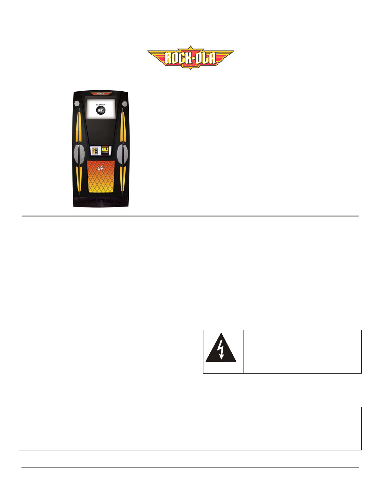
Slimline
Model SL-3 Set-Up and
Installation Guide
IMPORTANT SAFETY INSTRUCTIONS
a. Read these instructions.
b. Keep these instructions.
c. Follow all instructions.
d. Do not use this apparatus near water.
e. Clean only with dry cloth.
f. Do not block any ventilation openings. Install in
accordance with the manufacturer’s instructions.
g. Do not install near any heat sources such as radiators,
heat registers, stoves, or other apparatus (including
amplifiers) that produce heat.
h. Do not defeat the safety purpose of the polarized or
grounding-type plug. A polarized plug has two blades
with one wider than the other. A grounding-type plug
has two blades and a third grounding prong. The wide
blade or the third prong are provided fo r your safety. If
the provided plug does not fit into your outlet, consult an
electrician for replacement of the obsolete outlet.
i. Protect the power cord from being walked on or pinched
particularly at plugs, convenience receptacles, and the
point where they exit from the appliance.
This document contains information proprietary to Rock-Ola
Manufacturing Corporation and may not be reproduced, published or
distributed in any form or disclosed in whole or in part without written
authorization.
j. Only use attachments/accessories specified by the
manufacturer.
k. Unplug this apparatus during lightning storms or when
unused for long periods of time.
l. Refer all servicing to qualified service personnel.
Servicing is required when the apparatus has been
damaged in any way, such as power-supply cord or plug
is damaged, liquid has been sp illed or objects hav e fallen
into the apparatus, the apparatus has been exposed to rain
or moisture, does not operate normally, or has been
dropped.
WARNING: Terminals marked with the
lightening flash label are hazardous live.
The external wiring connected to these
terminals requires installation by an
instructed person or the use of readymade leads or cords.
Copyright ©2008
All Rights Reserved
Rock-Ola Manufacturing Corporation
2335 208th Street, Torrance, CA 90501
- 1 -
Page 2
Introduction
Rock-Ola® has teamed up with Peavey Electronics® to build
the most powerful standard jukebox. Optional power amplifiers
can provide up to 3,500 Wrms for concert level sound in
virtually any location.
The Rock-Ola Digital Jukebox is the heart of the Network in
the location. It controls the broadband access. The Broadband
Internet connectivity allows the jukebox to offer the patrons the
most powerful entertainment experience with such features as
Single Song Download. Hundreds of thousands of songs
updated weekly are available for play.
The Rock-Ola Jukebox operates in a completely
different manner than any CD machine or most
other downloading Jukeboxes. Please read this Set-
Up & Installation Guide and make sure each step is understood
before proceeding.
Additional information is contained on the Programming,
Service & Parts Manual CD, included in your service pack. An
index at the end of this Setup Guide describes the contents of
the Programming, Service & Parts Manual CD.
Jukebox Specifications
SPECIFICATIONS
Dimensions:
Uncrated:
Height 63”
Width 30”
Depth 20”
Weight 317 lbs
Crated:
Height 73”
Width 34”
Depth 29”
Weight 363 lbs
Amplifier:
Output Power:
Protection: Speaker overload
Voltage:
Frequency:
Maximum Power
Consumption:
Monitor:
SLI-Sx
900 Wrms
(450 x 2 @ 2 ohms)
High temperature
115VAC
60Hz
900 max watts
7.75 max amps
19” SAW LCD
Installing the Hard Drive
1. Locate the four brass thumbscrews located in a small
envelope inside the literature package. Thread a
thumbscrew into the threaded holes on the sides of the
drive at each corner.
2. Gently but firmly push the IDE cable into the 40 pin socket
noting which way the “bump” in the cable matches the
relief in the connector on the drive. Connect the power
cable to the drive next to the IDE cable with the yellow
wire facing the outside.
3. Slide the drive onto the Core chassis lining up the
thumbscrews with the slots in the brackets. Tighten the
thumbscrews.
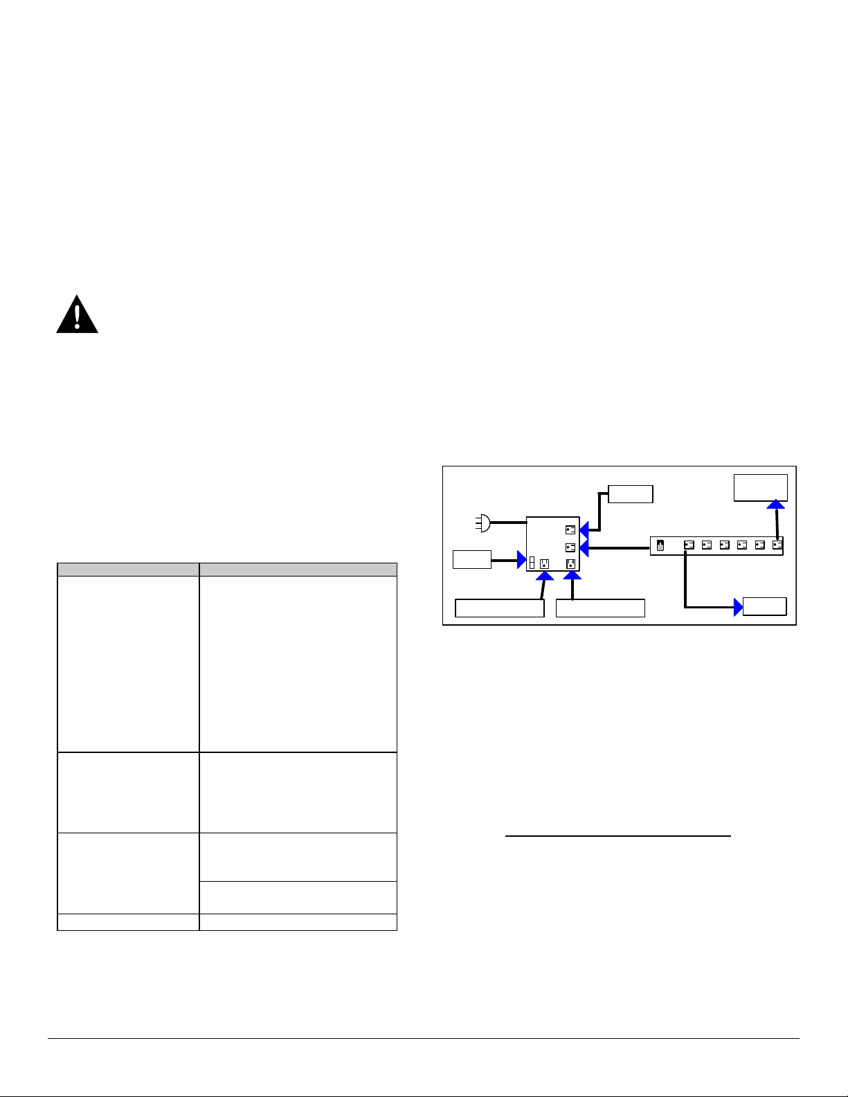
Location Power
The machines need a clean source of properly phased and
grounded 117VAC power at 10 Amps Max. This MUST
be provided 24 hours a day, 7 days a week. The outlet the
jukebox is connected to must NOT be controlled by a
switch nor can the circuit breaker feeding it be shut off at
night.
COMPUTE R
POWER
DISTRIBUTION
LIGHTS
POWER AMP #1 (REAR)
ROUTER
UPS
AMP1 AMP2
POWER AMP #2 (FRONT)
ROUTER
POWER STRIP
Refer to the block diagram above. The power distribution box
supplies line power to everything in the jukebox. The Power
Strip contains RFI, EMI, Surge, and Spike protection for the
computer.
The amplifier, computer core, and broadband communications
equipment are always on. When the location activates the
power button on the remote or the jukebox itself, the computer
stops the selection in play and shuts down the monitor, lights
and DBA. The computer core also has the capability of shutting
down the Router and Modem (if installed).
The Power Strip must not be removed
Running a system without a surge-protecting power strip
exposes all of the computer electronics to damage from surges,
noise interference, brown-outs, and power failures, all of which
reduce the life of the machine and cause poor performance.
Furthermore, not using surge-protecting power strip will void
the jukebox warranty.
CORE
PRE-AMP
.
4
Page 3
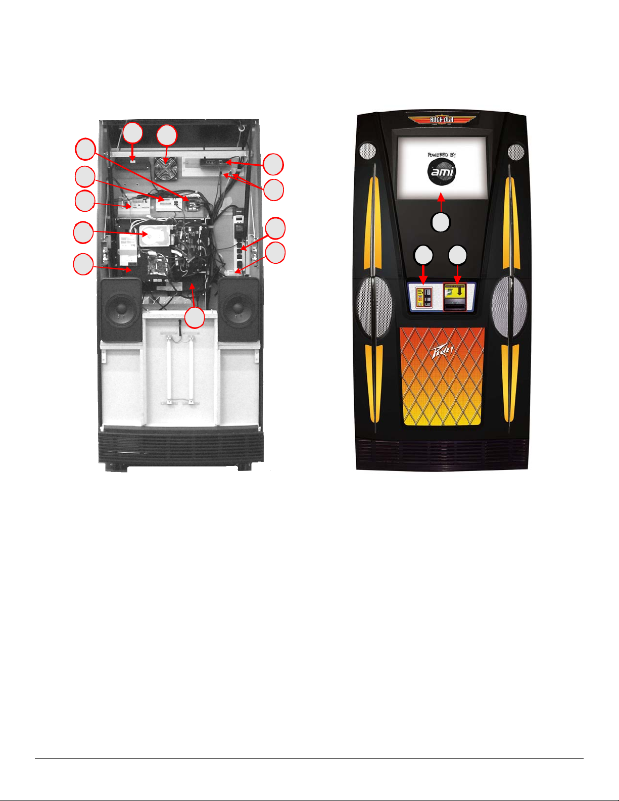
Major Component Locations
11
15
14
13
8
9
4
5
12
2
1
3
10
7
6
1. Touch Monitor
2. Credit Card Reader
3. Bill Acceptor
4. C ool i n g Fan
5. Router
6. Peavey 900 Power Amp (in compartment)
7. Po wer Di st ribution
8. RF Remo te Receiver Assy
9. C ont rol Amplifier
10. Power Strip
11. LED Controller
12. Reset Buttons
13. 4-Channel Wired Remote Control
14. Computer Core
15. Hard Drive
4
Page 4

Power Up
WARNING
Use of adapters or removal of the grounding pin of
the plug may create a potential shock hazard and
will defeat the surge protection devices causing
erratic operation or destruction of the electronic
assemblies and void all warranties.
1. Turn the Power Strip Switch ON . The protection and
ground indicators should light. If the ground indicator
does not light, STOP and investigate the problem with
the grounding. Do NOT continue to operate the
jukebox in an ungrounded state. Not only is it harmful
to the electronics, it is a SERIOUS SAFETY
HAZZARD.
2. The Core will power up automatically. The system will
load and re-boot several times. This is normal and part
of the hardware detection process.
When the system has finished loading and the album covers
are showing, the lights should be on and the DBA arrows
flashing.
Touchscreen Calibration
Press the “Calibrate” button on the front of the “Rowelink”
controller located at the bottom of the Core.
Follow the on-screen instructions to complete calibration
Shut Down
To shut down the system for moving or service, move the
main switch on the Power Strip to the OFF position.
The jukebox may now be unplugged.
Router and Other Customer
Premise Equipment (CPE)
The Rock-Ola/AMi Entertainment System requires a
broadband Internet connection to operate. This can come in
the form of a DSL Modem, Cable Modem, or Satellite. For
your convenience, a router that has been pr e-programmed is
installed in the jukebox from the factory. You will need to
install a modem. This Internet equipment is called Customer
Premise Equipment (CPE).
It is highly recommended that the CPE is located inside the
jukebox for two reasons. First, it is yours.
wishes to use your broadband connection for other purposes
such as a food & beverage computer system or a PC in their
office, you can lease a port to them as extra income.
If the location
Second, if the CPE needs to be reset, the jukebox can cycle
the power
In order to locate a modem inside a wall mounted jukebox,
a means of connecting two power cubes to the CPE Outlet
is required.
A pigtail power cord is connected to the CPE power outlet
located on the right hand side of the Power Box Assembly.
The router’s power cube is already plugged into it. The
open side of the pigtail connector is for the modem’s power
cube. (See Figure 5-B). DO NOT connect either the modem
or router power to the UPS or power strip. If you do, the
jukeboxes router reset system will not function.
PIGTAI L
CPE OUTLET
If you are upgrading a location that had a broadband
connected jukebox before, you may be able to use the CPE
that is already there. Should that be the case, follow the
Installing CPE procedure outlined below. If you wish to
leave the CPE outside the jukebox, proceed to the “External
Router” portion of this section.
Installing CPE:
1. Install the modem at a location inside the jukebox that
will not interfere with the door closing or block air flow
from the cabinet cooling fans.
2. Connect the Modem and Router Power Cubes as shown
in Figure 5-B.
3. Using a short CAT5 LAN cable, connect the computer
core to Ethernet output #1 on the router.
4. Connect a short CAT5 LAN Cable from the Modem’s
Ethernet Connector to the Modem connector on the
Router.
5. Be sure power switches (if present) are set to “ON”.
ROUTE
POWER
CUBE
MODEM
POWER
CUBE
4
Page 5

A
WARNING: Do NOT press the reset button on the back of
the router unless directed to do so by AMI personnel. It has
been programmed to operate with the AMI Entertainment
Network and a reset will erase all of the settings.
External Router if it determined to be advantageous to
have the router outside the jukebox.
TO CORE TO MODEM POWER
Figure 6-B
- Router
DO NOT
TOUCH
¾ Run a LAN cable from the Ethernet output of the router
to the LAN connection on the computer core. (See
Figure 7-B)
¾ Be sure the modem and router are powered up then
perform the CPE Test.
FROM:
TELEPHONE LINE
or CABLE
SL or CABLE
ODEM
INPUT
OUTPUT
(WAN )
INP UT
(MODEM)
MI ROUTER
(ETHERNET)
OUTPUT
TO: LAN
CON NE CTO R O N
COMPUTER CORE
Figure 7-B – Internet Equipment (CPE) Diagr am
Testing the CPE
When all the network connections have been made, boot up the jukebox. Enter the service mode by pressing and releasing the service
button on the Rowelink Controller Assembly.
¾ Touch Diagnostics > Network Information > IP Configuration. Display should show;
HOST NAME: The hard drive’s ID number
*IP ADDRESS: 192.168.0.1XX
*DEFAULT GATEWAY: 192.168.0.1
*DHCP SERVER: 192.168.0.1
¾ Touch Network Status
Two test buttons will be shown along with status screens.
¾ Touch Gateway (LAN) Button. This test checks the operation of the Router and Core Computer Network Interface Card. Wait for
test to finish. The test is successful if the last line in the LAN window is “Trace Co mplete.”
¾ Touch “Server (WAN) Button. This will test the path to the AMI servers. It may take several minutes for the test to complete. The
test is successful if the last line in the WAN window is “Trace complete.”
If all tests pass, the system is ready to use.
* Assuming the default setup is used. If default setup is not used, the IP, Default Gateway and DHCP Server addresses will be as set in
the new configuration. Should it be necessary to re-program the router for a specific network configuration, see “Programming the
Router” in the Network Setup, Jukebox Operation and Operator Setup Screens Manual.
4
Page 6

Hidden Reset Buttons Location
Be sure the establishment knows the location of the hidden Reset buttons.
The buttons are accessed from the rear of the cabinet, as shown in the illustration. Two small holes in the cabinet allow a small,
pointed object, such as a toothpick or swizzle stick, to press the reset buttons through the holes.
CPE (ROUTER)
RESET
ATX (MASTER)
RESET
15
Page 7

Recommended Routine Maintenance of the Slimline
Digital-Downloading Jukebox
Heat is the biggest enemy of electronic components. Proper maintenance is essential for maximum earnings and reliability.
It is very important to keep all cooling fans clean. Once dust and dirt is visible on a cooling fan, the airflow is reduced by at least 25%.
There are several cooling fans in the Rock-Ola jukebox (see illustration, next page.)
Recommended preventative maintenance:
Routine Service. Performed at each collection and takes about 3 minutes.
1. Check that the cabinet cooling fan is not blocked.
2. Check CPU fan from the “Health Status” screen.
3. Visually inspect the Power Supply Fan for operation. It should be spinning at a high speed at all times.
4. Visually inspect the amplifier fan for operation. It should be spinning at a low speed if not playing and a higher speed if
playing.
5. Be sure nothing is resting on top of a wall unit or otherwise blocking the airflow around any machine.
Collecting from the DBA
1. To remove the bill stacker, slide the tab on the top of the DBA upward s and pull the stacker towards the back of the jukebox.
2. Open the side door on the bill stacker to remove the cash.
3. Slide the bill stacker back on the DBA. Be sure the green arrows are flashing.
Minor Service. Perform a minimum of every 3 months if operating more than 14 hours per day, operating where smoking is
allowed, or otherwise a dusty environment. Perform a minimum of every 6 months if operated less than 14 hours per day in a very
clean environment. You will need a new, soft 2” paintbrush*.
1. Gently, brush* dirt from the cabinet cooling fan. Verify operati on
2. Brush* dirt from the power supply fan.
3. Brush* dirt from the amplifier fan.
4. Check the operation of the CPU fan from the “health status” screen.
5. Listen to the power supply fan and CPU fan for excessive noise or vibration.
6. Be sure the amplifier fan is running.
7. Clean the DBA with an approved cleaning card.
8. Clean the Credit Card Reader with an approved cleaning card.
9. Clean and calibrate the touchscreen.
Cleaning the Touch Screen
Any standard glass cleaner can be used to clean the touchscreen. Always spray the glass cleaner on the cloth or towel and clean the
touchscreen. Glass cleaner sprayed directly on the monitor could possibly leak inside and cause damage.
Annual Service. Perform every year in addition to everything in the minor service.
1. Check fluorescent lamps for excessive blackening of the ends or flickering. Replace if necessary.
2. Vacuum the interior of the cabinet and fans.
3. Inspect the power cord for fraying or damage and check power ground.
4. Check all LAN connections and wiring.
5. Listen to all speakers to make sure they are operating correctly.
Scheduled Maintenance always costs less in time and money than an unscheduled breakdown.
Page 8

CABINET FAN
CPU FAN
INSIDE
POWER SUP PLY
FAN
AMPLIFIER
FAN
 Loading...