

Page 1
SERIES
Q Series Graphic Equalizers
Q215B
QF215
QF131
™
OPERATING MANUAL
Page 2
2
Intended to alert the user to the presence of uninsulated “dangerous voltage” within the product’s
enclosure that may be of sufficient magnitude to constitute a risk of electric shock to persons.
Intended to alert the user of the presence of important operating and maintenance (servicing)
instructions in the literature accompanying the product.
CAUTION: Risk of electrical shock — DO NOT OPEN!
CAUTION: To reduce the risk of electric shock, do not remove cover. No user serviceable parts inside. Refer
servicing to qualified service personnel.
WARNING: To prevent electrical shock or fire hazard, do not expose this appliance to rain or moisture. Before
using this appliance, read the operating guide for further warnings.
Este símbolo tiene el propósito, de alertar al usuario de la presencia de “(voltaje) peligroso” sin aislamiento dentro de la caja del producto y que puede tener una magnitud suficiente como para constituir
riesgo de descarga eléctrica.
Este símbolo tiene el propósito de alertar al usario de la presencia de instruccones importantes sobre la
operación y mantenimiento en la información que viene con el producto.
PRECAUCION: Riesgo de descarga eléctrica ¡NO ABRIR!
PRECAUCION: Para disminuír el riesgo de descarga eléctrica, no abra la cubierta. No hay piezas útiles dentro.
Deje todo mantenimiento en manos del personal técnico cualificado.
ADVERTENCIA: Para evitar descargas eléctricas o peligro de incendio, no deje expuesto a la lluvia o humedad
este aparato Antes de usar este aparato, Iea más advertencias en la guía de operación.
Ce symbole est utilisé dans ce manuel pour indiquer à l’utilisateur la présence d’une tension dangereuse
pouvant être d’amplitude suffisante pour constituer un risque de choc électrique.
Ce symbole est utilisé dans ce manuel pour indiquer à l’utilisateur qu’il ou qu’elle trouvera d’importantes
instructions concernant l’utilisation et l’entretien de l’appareil dans le paragraphe signalé.
ATTENTION: Risques de choc électrique — NE PAS OUVRIR!
ATTENTION: Afin de réduire le risque de choc électrique, ne pas enlever le couvercle. Il ne se trouve à l’intérieur
aucune pièce pouvant être reparée par l’utilisateur. Confiez I’entretien et la réparation de l’appareil à un réparateur
Peavey agréé.
AVERTISSEMENT: Afin de prévenir les risques de décharge électrique ou de feu, n’exposez pas cet appareil à la
pluie ou à l’humidité. Avant d’utiliser cet appareil, lisez attentivement les avertissements supplémentaires de ce
manuel.
Dieses Symbol soll den Anwender vor unisolierten gefährlichen Spannungen innerhalb des Gehäuses
warnen, die von Ausreichender Stärke sind, um einen elektrischen Schlag verursachen zu können.
Dieses Symbol soll den Benutzer auf wichtige Instruktionen in der Bedienungsanleitung aufmerksam
machen, die Handhabung und Wartung des Produkts betreffen.
VORSICHT: Risiko — Elektrischer Schlag! Nicht öffnen!
VORSICHT: Um das Risiko eines elektrischen Schlages zu vermeiden, nicht die Abdeckung enfernen. Es befinden
sich keine Teile darin, die vom Anwender repariert werden könnten. Reparaturen nur von qualifiziertem
Fachpersonal durchführen lassen.
ACHTUNG: Um einen elektrischen Schlag oder Feuergefahr zu vermeiden, sollte dieses Gerät nicht dem Regen
oder Feuchtigkeit ausgesetzt werden. Vor Inbetriebnahme unbedingt die Bedienungsanleitung lesen.
Page 3

3
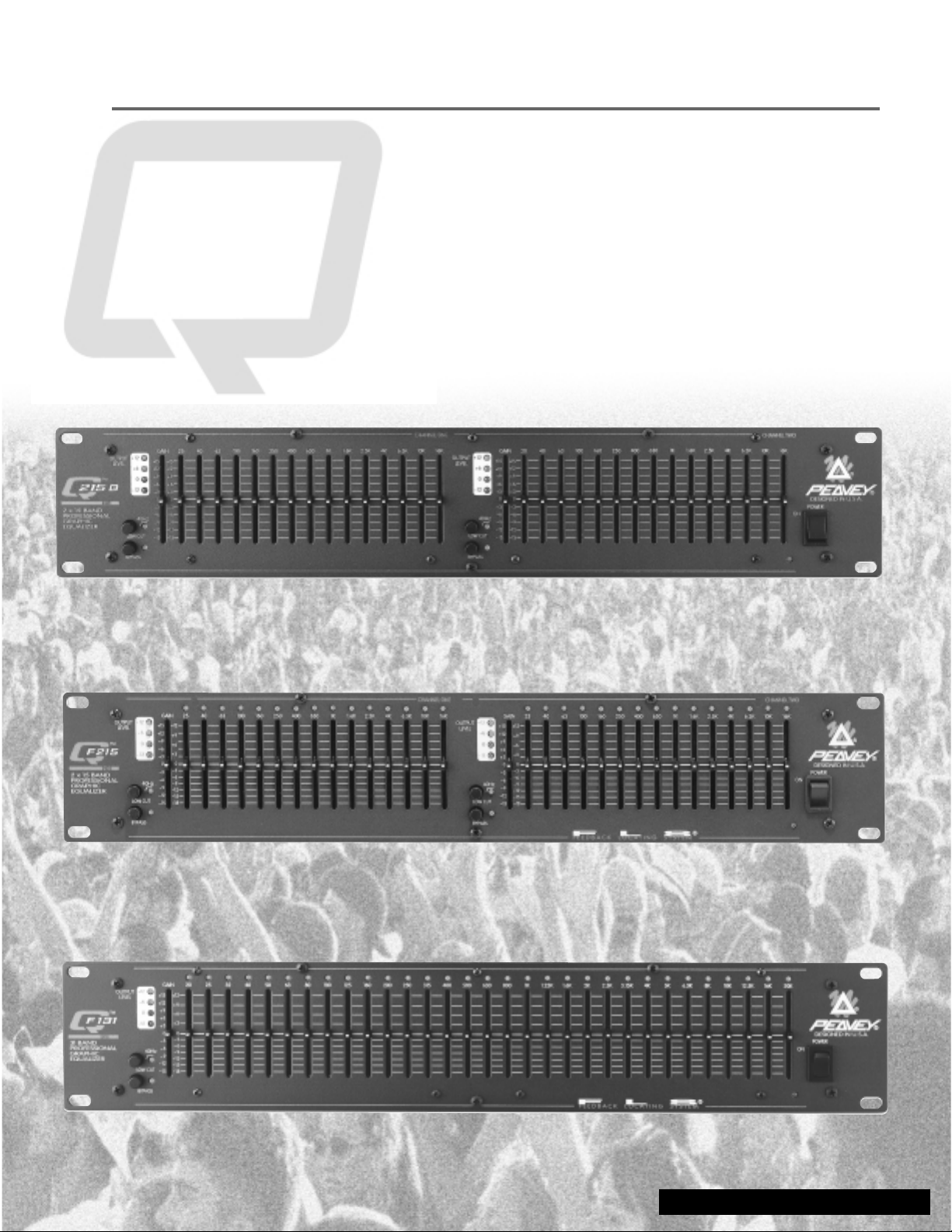
Q™SERIES EQUALIZERS
Thank you for purchasing a Peavey Electronics Q Series graphic equalizer. The Q family features
two dual-channel models and one single-channel unit, all incorporating Peavey’s legendary lownoise, low-distortion design. Ruggedly constructed, Q Series EQs have 45 mm, center-detented
control sliders enclosed in metal for durability. These two rack-space units also offer ±15 dB gain
control and an LED display indicating output level. Other shared features include switchable low-cut
filters, +21 dBu balanced inputs and outputs, and bypass switches. Q Series equalizer filters are set
at ISO center frequencies within 3% accuracy. Whether on stage, in the studio, or simply tweaking
your home hi-fi system, the Q Series has an EQ for you.
FEATURES
Q 215B
• Dual channel (15 bands per channel)
• 2/3 octave filter sets
• 25 Hz to 16 kHz effective equalization range
• Constant Q filters
• 15 dB boost / 15 dB cut per band
• Output level LEDs (-12 to +12 dB)
• 18 dB per octave 40 Hz low-cut filter with status LED
• 1/4" TRS inputs and outputs for balanced or unbalanced operation
• Bypass switch with status LED
• 15 dB boost / 15 dB cut Gain Control
QF 215
• Dual channel (15 bands per channel)
• 2/3 octave filter sets
• 25 Hz to 16 kHz effective equalization range
• Constant Q filters
• 12 dB boost / 18 dB cut per band
• Output level LEDs (-12 to +12 dB)
• 18 dB per octave 40 Hz low-cut filter with status LED
• XLR and 1/4" TRS inputs/outputs for balanced or unbalanced operation
• Bypass switch with status LED
• New FLS (Feedback Locating System) circuitry for improved sensitivity
• 15 dB boost / 15 dB cut Gain Control
QF 131
• Single channel (31 band)
• 1/3 octave filter sets
• 20 Hz to 20 kHz effective equalization range
• Constant Q filters
• 12 dB boost / 18 dB cut per band
• Output level LEDs (-12 to +12 dB)
• 18 dB per octave 40 Hz low-cut filter with status LED
• XLR and 1/4" TRS inputs/outputs for balanced or unbalanced operation
• Bypass switch with status LED
• New FLS
®
(Feedback Locating System) circuitry for improved sensitivity
• 15 dB boost / 15 dB cut Gain Control
ENGLISH
Page 4
4
EQUALIZATION PROCESS
Always begin the equalization process with all sliders at their center-detent (flat response) positions.
For units equipped with FLS
®
, increase system volume until slight feedback occurs. Note the LED(s)
that illuminate, and lower the corresponding fader(s) until feedback is eliminated. In other words, see
the light pull down the fader. For the Q 215B, lower each fader until the feedback frequency is
found. Lower the faders in small amounts to avoid adversely affecting sound quality. Likewise,
excessive boosting of a frequency may result in feedback.
EXERCISE CAUTION WHEN ATTEMPTING TO BOOST FREQUENCIES BELOW SPEAKER
SYSTEM TRANSDUCER CUT-OFF.
Typical sound reinforcement enclosures are not designed for 20 Hz performance, and transducer
damage could result from “over-boosting” low frequencies. Excessive boost at very low frequencies
could also limit overall system headroom. Engaging the 40 Hz low-cut filter is the best way to avoid
these problems.
NOTE: Superb tonality, absence of feedback, and great-sounding systems may not be possible with
any graphic equalizer. All other system components must be of high quality and designed for the
application. No amount of equalization will correct an acoustically bad room, bad
microphone/speaker arrangement, or completely correct the response curve of a poor loudspeaker.
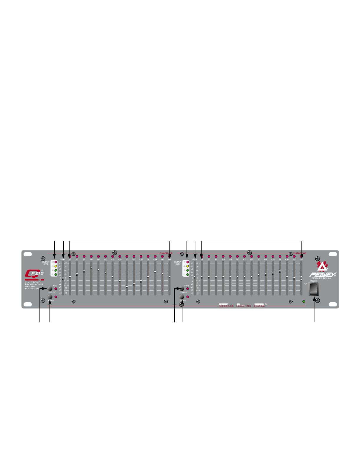
FEATURES AND CONTROLS
FRONT PANEL
(1) OUTPUT LEVEL LED METER
This LED array indicates output level from –12 dB to +12 dB.
(2) GAIN
This calibrated, detented control regulates overall gain of the EQUALIZER SECTION (3).
Unity gain throughout the signal chain can be maintained by recovering lost signal gain at this
point. The equalization process may result in noticeable signal loss. To compensate for this
loss, engage the BYPASS (5) switch and compare the signal level with that of the equalized
level. Increase the GAIN control until the equalized level approximates that of the bypassed
level. Let your ears be your guide.
142 1 23 3
5 4 5 6
Page 5
5
(3) EQUALIZER SECTION
These calibrated, detented controls adjust the amount of cut or boost at their respective
frequencies. They are adjustable from 18 dB cut to 12 dB boost (15 dB cut to 15 dB boost on
the 215B). For units equipped with FLS, the LED at the top of each band will illuminate as an
indication of feedback at that frequency.
(4) LOW-CUT FILTER
This switch activates the low-cut filter that rejects frequencies below 40 Hz. Frequency roll off
is 18 dB per octave with the switch engaged. This filter will operate even with the BYPASS (5)
switch engaged. The adjacent red LED indicates activation.
(5) BYPASS
This switch allows the signal to bypass the unit with the exception of the LOW-CUT FILTER
(4). When this switch is engaged, the signal is routed from INPUT (10 and 11) though the
low-cut filter to output (8 and 9).
(6) POWER
This 2-position rocker switch applies mains power to the unit when in the ON position. The
adjacent green LED indicates mains power activation.
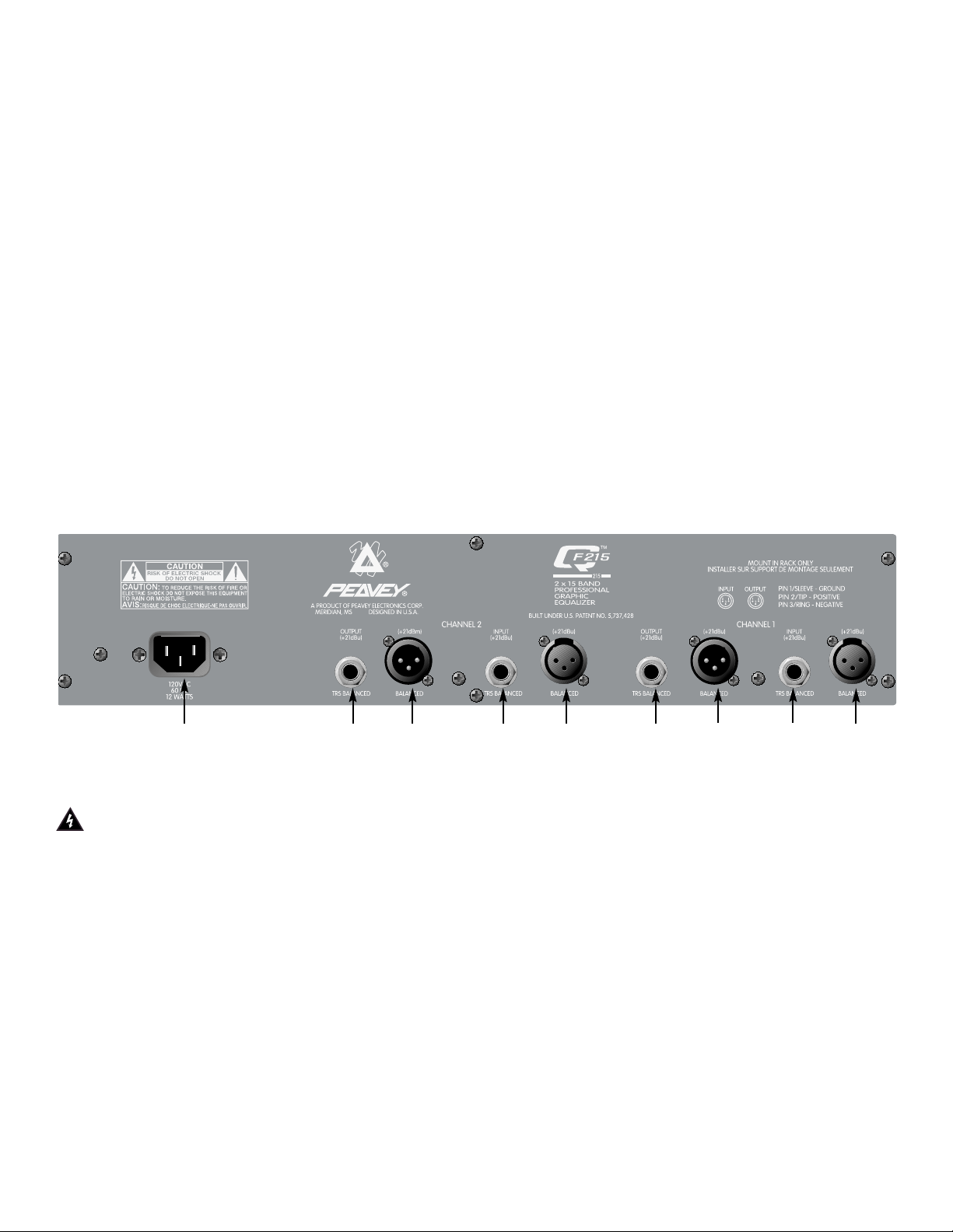
REAR PANEL
(7) IEC MAINS CONNECTOR
This is a standard IEC power connector. An AC mains cord having the appropriate AC plug
and ratings for the intended operating voltage is included in the carton.
Never break off the ground pin on any equipment. It is provided for your safety. If the outlet used
does not have a ground pin, a suitable grounding adapter should be used and the third wire should
be grounded properly. To prevent the risk of shock or fire hazard, always be sure that the equalizer
and all associated equipment is properly grounded.
NOTE: FOR UK ONLY
If the colors of the wires in the mains lead of this unit do not correspond with the colored markings
identifying the terminals in your plug, proceed as follows: (1) The wire that is colored green and
yellow must be connected to the terminal that is marked by the letter E, the earth symbol, colored
green, or colored green and yellow. (2) The wire that is colored blue must be connected to the
terminal that is marked with the letter N or the color black. (3) The wire that is colored brown must
be connected to the terminal that lis marked with the letter L or the color red.
789 10 11
8
9 10
11
Page 6

6
(8) TRS BALANCED OUTPUT
These 1/4" Tip/Ring/Sleeve (stereo) jacks provide balanced output when used with TRS
connectors and 2-conductor shielded cables. When used with a mono 1/4" (TS) phone plug,
the output is unbalanced.
(9) XLR OUTPUT
These male 3-pin connectors provide balanced output when used with female XLR
connectors.
(10) TRS BALANCED INPUT
These1/4" Tip/Ring/Sleeve (stereo) jacks provide balanced input when used with TRS
connectors and 2-conductor shielded cables. When used with mono 1/4" (TS) phone plugs,
the input is unbalanced.
(11) XLR INPUT
These female 3-pin connectors provide balanced input when used with male XLR connectors.
Page 7
7
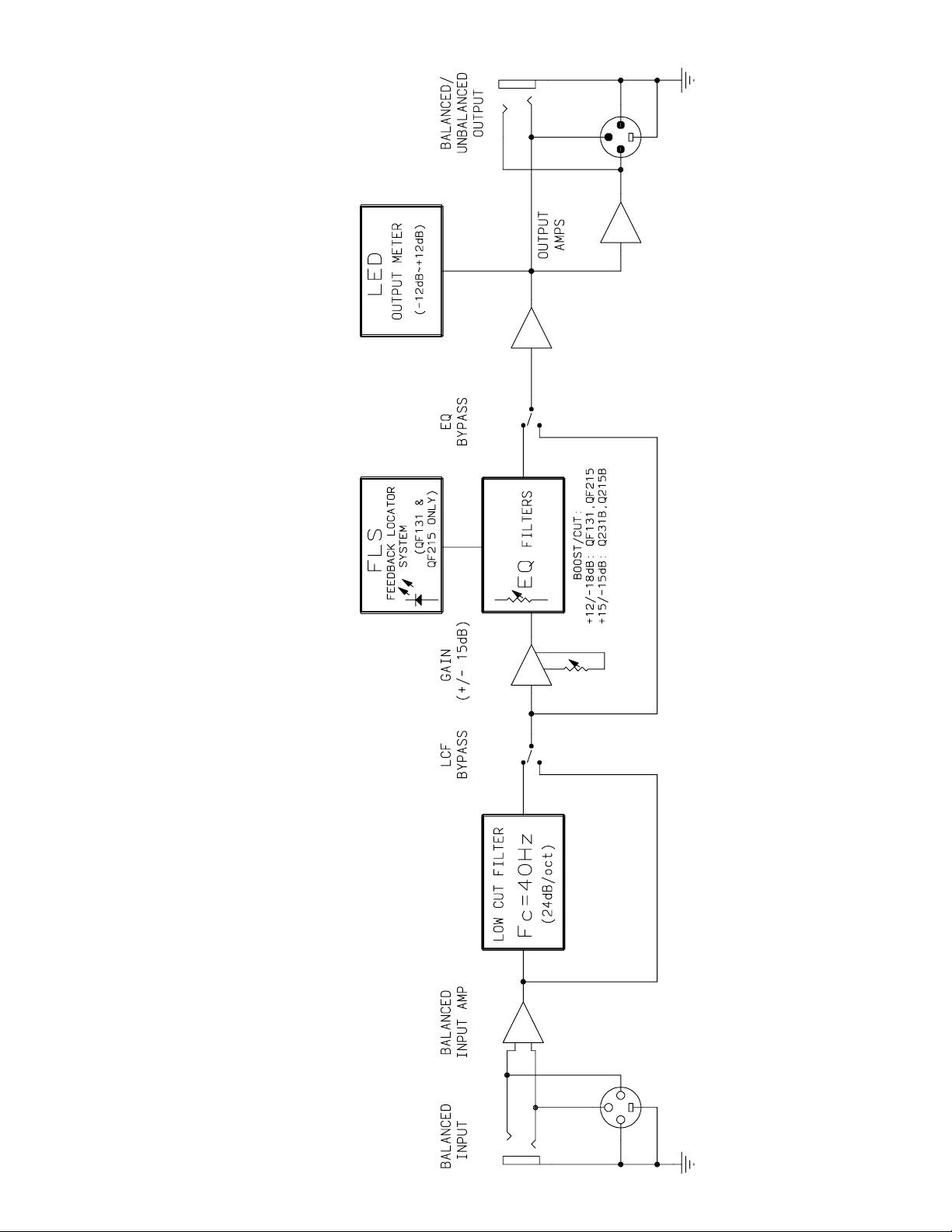
Q
™
SERIES BLOCK DIAGRAM
Page 8

8
SPECIFICATIONS* Q™F131 Q™ 215B Q™F215
Filter Q 4.77 2.3 2.3
Filter Frequencies (Hz) 20, 25, 32, 40, 50, 63, 80, 25, 40, 63, 100, 160 25, 40, 63, 100, 160,
100, 125, 160, 200, 250, 250, 400, 630, 1 K, 1.6 K, 250, 400, 630, 1 K, 1.6 K,
315, 400, 500, 630, 800, 2.5K, 4 K, 6.3K, 10 K, 16 K 2.5 K, 4 K, 6.3 K, 10 K, 16 K
1 K, 1.25 K, 1.6 K, 2 K, 2.5 K,
3.15 K, 4 K, 5 K, 6.3 K, 8 K,
10 K, 12.5 K, 16 K, 20 K
Maximum Boost
and Cut Filter +12 dB / -18 dB +15 dB / -15 dB +12 dB / -18 dB
Output Noise
Bypass Mode -101 dBV -100 dBV -100 dBV
Filter Mode (Flat) -95 dBV -98 dBV -98 dBV
ALL MODELS
Frequency Response: ± 1 dB (20 Hz – 20 kHz)
Distortion: .002% (20 Hz – 20 kHz)
Input Impedance: Balanced 20 K ohms (equal impedances to ground)
Output Impedance: 660 ohms
Maximum Input Level: +18 dBV (8 V RMS)
Maximum Output Level: -18 dBV unbalanced; +21 dBV balanced
Nominal Input Level: 0 dBV (1 V RMS)
Nominal Output Level: 0 dBV (1 V RMS)
Input Headroom: Nominal 18dB
Output Headroom: 18 dB
Maximum Boost and
Cut Gain: +15 dB / -15 dB
Low Cut Filter: 40 Hz @ 18 dB per octave
Power Consumption: Domestic: 120 VAC, 60 Hz, 12 Watts
Export: 220/230 VAC, 50/60 Hz, 12 Watts
Dimension: 3.5" (89 mm) H x 19" (483 mm) W x 7.375" (187 mm) D
Weight: 7.8 lbs. (3.54 kg)
* All specifications are typical unless otherwise noted. 0 dBV = 1 volt. All specifications are referenced to nominal
output level (0 dBV) unless otherwise stated.
NOTE: All specifications measured at 1 V RMS input, unbalanced output, sliders at mid position, and all switches out
unless otherwise noted.
Page 9

9
ESPAÑOL
ECUALIZADORES Q™SERIES
Gracias por su compra de un ecualizador gráfico serie Q de Peavey. La familia Q es caracterizada
por dos modelos de canales dobles y unidades de un solo canal, todas incorporando el diseño
legendario de Peavey de bajo ruido y baja distorsión. Construidos fuertemente, los ecualizadores de
la serie Q de Peavey cuentan con sliders con punto de detención medio de 45 mm incrustados en
metal para durabilidad. Estas unidades de dos espacios de rack también ofrecen controles de
ganancia de ±15 dB e indicadores LED de nivel de salida. Otras características incluyen filtros de
graves ajustables, entradas y salidas de + 21 dBu e interruptores de bypass. Los filtros de los
ecualizadores de la serie Q están centrados en frecuencias ISO a un 3% de exactitud. Ya sea en el
escenario, en el estudio o simplemente arreglando el sonido del estéreo de casa, la serie Q tiene un
ecualizador para ti.
CARACTERISTICAS
Q 215B
• Canales dobles (15 bandas por canal)
• Filtros de 2/3 de octava
• Rango de ecualización efectiva de 25 Hz 16 kHz
• Filtros Q constantes
• 15 dB recorte / 15 dB aumento por banda
• LEDs de nivel de salida(-12 a +12 dB)
• Filtro de recorte de graves a 40 Hz de18 dB por octava
• Entradas y salidas TRS de 1/4" para operación balaceada y no balanceada
• Interruptor Bypass con LED de estatus
• Control de ganancia de15 dB recorte / 15 dB aumento
QF 215
• Canales dobles (15 bandas por canal)
• Filtros de 2/3 de octava
• Rango de ecualización efectiva de 25 Hz 16 kHz
• Filtros Q constantes
• 18 dB recorte / 15 dB aumento por banda
• LEDs de nivel de salida(-12 a +12 dB)
• Filtro de recorte de graves a 40 Hz de18 dB por octava
• Entradas y salidas TRS de XLR y 1/4" para operación balaceada y no balanceada
• Interruptor Bypass con LED de estatus
• Nuevos circuitos FLS (Feedback Locating System –sistema contra la retroalimentación) para
sensibilidad mejorada
• Control de ganancia de15 dB recorte / 15 dB aumento
QF 131
• Canal sencillo (31 bandas)
• Filtros de 1/3 de octava
• Rango de ecualización efectiva de 20 Hz 20 kHz
• Filtros Q constantes
• 18 dB recorte / 12 dB aumento por banda
Page 10

10
• LEDs de nivel de salida(-12 a +12 dB)
• Filtro de recorte de graves a 40 Hz de18 dB por octava
• Entradas y salidas TRS de XLR y 1/4" para operación balaceada y no balanceada
• Interruptor Bypass con LED de estatus
• Nuevos circuitos FLS
®
(Feedback Locating System –sistema contra la retroalimentación) para
sensibilidad mejorada
• Control de ganancia de15 dB recorte / 15 dB aumento
PROCESO DE ECUALIZACIÓN
Siempre comienza el proceso de ecualización con todos los sliders en su posición central
(respuesta plana). Para unidades equipadas con el sistema FLS®, incrementa el volumen del
sistema hasta que ocurra la retroalimentación. Nota que el LED(s) que se ilumina y recorta el
slider(s) correspondiente a esa frecuencia hasta que desaparezca la retroalimentación. En otras
palabras puedes ver la luz para bajar el slider. Para el Q 215B, baja cada slider hasta que la
frecuencia de retroalimentación sea encontrada. Baja los sliders con movimientos pequeños para
evitar cambios drásticos en la calidad del sonido. Así mismo, los aumentos excesivos de
frecuencias pueden resultar en retroalimentación.
HAY QUE TENER CUIDADO CUANDO SE TRATE DE INCREMENTAR FRECUENCIAS POR
DEBAJO DEL PUNTO DE RECORTE DE LOS TRANSDUCTORES DE LOS SISTEMAS
Las bocinas típicas de reproducción de música no están diseñadas para frecuencias de 20 Hz, y los
transductores pueden ser dañados por sobrecargas en frecuencias graves. Los incrementos
excesivos en frecuencias muy graves también pueden limitar el umbral del sistema entero.
Encender el filtro de graves de 40 Hz es la mejor manera de evitar estos problemas.
NOTA: Conseguir tonalidad superior, ausencia de retroalimentación y calidad de sonido pueden no
siempre ser posibles con cualquier ecualizador gráfico. Todos los demás elementos deben ser de
alta calidad y diseñados para la aplicación. Ninguna cantidad de ecualización puede corregir un
cuarto con mala acústica, mal posicionamiento de micrófonos/ bocinas, o completamente corregir o
cambiar la curva de frecuencias de una bocina mala.
CARACTERÍSTCAS Y CONTROLES
PANEL FRONTAL
(1) MEDIDOR DE LED DE NIVEL DE SALIDA
Esta serie de LEDs indica el nivel de salida de –12 dB a + 12 dB
142 1 23 3
5 4 5 6
Page 11

11
(2) GANANCIA
Este control calibrado regula la ganancia general de la SECCIÓN DEL ECUALIZADOR (3).
La ganancia unitaria a través de la cadena de la señal se puede mantener recuperando la
ganancia de la señal en este punto. El proceso de ecualización puede dar como resultado
pérdida de señal perceptible. Para compensar esta pérdida, activa el interruptor de BYPASS
(5) y compara el nivel de la señal con el nivel del ecualizador. Incrementa el control de
GANANCIA hasta que el ecualizador aproxime el nivel de la señal de bypass. Deja que tus
oídos sean tu guía.
(3) SECCIÓN DEL ECUALIZADOR
Estos controles calibrados con centro marcado ajustan la cantidad de incremento o recorte
de sus respectivas frecuencias. Son ajustables de 18 dB de recorte a 12 dB de incremento
(12 dB de recorte a 15 dB de incremento en el 215B). Para unidades equipadas con FLS
(sistema contra retroalimentación), el LED encima de cada banda se iluminará como
indicador de retroalimentación en esa frecuencia.
(4) FILTRO DE RECORTE DE GRAVES
Este interruptor activa el filtro de recorte de graves que no acepta frecuencias debajo de los
40 Hz. La pérdida de frecuencias (roll-off) es de 18 dB por octava con el interruptor activado.
Este filtro operará inclusive con el interruptor de BYPASS (5) activado. El LED adyacente
indica su activación.
(5) BYPASS
Este interruptor permite que la señal pase por la unidad sin ser afectada, a excepción del
FILTRO DE RECORTE DE GRAVES (4). Cuando el interruptor está activado, la señal es
mandada de la ENTRADA (10 y 11), a través del filtro de graves a la salida (8 y 9).
(6) CORRIENTE
Este interruptor de dos posiciones aplica corriente a la unidad cuando está en la posición de
encendido (ON). El LED verde adyacente indica que la unidad está recibiendo corriente.
PANEL TRASERO
(7) CONECTOR PRINCIPAL DE CORRIENTE
Este es un conector IEC estándar. Un cable de CA con los requisitos necesarios de voltaje
es incluido en el paquete.
789 10 11
8
9 10
11
CAUTION
CAUTION:
TO REDUCE THE RISK OF FIRE OR
ELECTRIC SHOCK DO NOT EXPOSE THIS EQUIPMENT
TO RAIN OR MOISTURE.
AVIS:
RISQUE DE CHOC ELECTRIQUE-NE PAS OUVRIR.
230V
50/60 Hz
12 WATTS
A PRODUCT OF PEAVEY ELECTRONICS CORP.
MERIDIAN, MS DESIGNED IN U.S.A.
OUTPUT
(+21dBu)
TRS BALANCED
(+21dBm)
BALANCED
TM
F
215
215
2 x 15 BAND
PROFESSIONAL
GRAPHIC
EQUALIZER
CHANNEL 2 CHANNEL 1
BUILT UNDER U.S. PATENT NO. 5,737,428
INPUT
(+21dBu)
TRS BALANCED
(+21dBu)
BALANCED
OUTPUT
(+21dBu)
TRS BALANCED
BALANCED
MOUNT IN RACK ONLY
INSTALLER SUR SUPPORT DE MONTAGE SEULEMENT
INPUT
OUTPUT
21
12
3
3
(+21dBu)
PIN 1/SLEEVE - GROUND
PIN 2/TIP - POSITIVE
PIN 3/RING - NEGATIVE
INPUT
(+21dBu)
TRS BALANCED
(+21dBu)
BALANCED
Page 12

12
Nunca se rompa el tercer contacto de tierra de ningún aparato. Este ha sido incluido por seguridad.
Si la fuente de corriente no cuenta con una conexión de tierra, se debe utilizar un adaptador con
tierra y el tercer contacto debe ser aterrizado propiamente. Para prevenir el riesgo de toques
eléctricos o fuego, siempre hay que asegurarse que el ecualizador y todo el equipo con él asociado
está propiamente aterrizado.
(8) SALIDA BALANCEADA TRS
Estos conectadores de 1/4" estéreo (punta, anillo, manga) proveen salida balanceada
cuando se use conectores TRS y cables de 2 conductores sellados. Cuando se use un cable
mono de 1/4" (TS) tipo pone, la salida no es balanceada.
(9) SALIDA XLR
Estos 3 conectadores masculinos proveen salida balanceada cuando se usan conectores
XLR femeninos.
(10) ENTRADA BALANCEADA TRS
Estos conectadores de 1/4" estéreo (punta, anillo, manga) proveen entrada balanceada
cuando se use conectores TRS y cables de 2 conductores sellados. Cuando se use un cable
mono de 1/4" (TS) tipo phone, la entrada no es balanceada.
(11) ENTRADA XLR
Estos 3 conectadores femeninos proveen entrada balanceada cuando se usan conectores
XLR masculinos.
Page 13

13
ESPECIFICACIONES* Q™F131 Q™ 215B Q™F215
Filtro Q 4.77 2.3 2.3
Frecuencias filtradas (Hz) 20, 25, 32, 40, 50, 63, 80, 25, 40, 63, 100, 160 25, 40, 63, 100, 160,
100, 125, 160, 200, 250, 250, 400, 630, 1 K, 1.6 K, 250, 400, 630, 1 K, 1.6 K,
315, 400, 500, 630, 800, 2.5K, 4 K, 6.3K, 10 K, 16 K 2.5 K, 4 K, 6.3 K, 10 K, 16 K
1 K, 1.25 K, 1.6 K, 2 K, 2.5 K,
3.15 K, 4 K, 5 K, 6.3 K, 8 K,
10 K, 12.5 K, 16 K, 20 K
Incremento máximo
y filtros de recort +12 dB / -18 dB +15 dB / -15 dB +12 dB / -18 dB
Ruido de salida
Modo Bypass -101 dBV -100 dBV -100 dBV
Modo Filtrado (Plano) -95 dBV -98 dBV -98 dBV
TODOS LOS MODELOS
Respuesta de Frecuencias: ± 1 dB (20 Hz – 20 kHz)
Distorsión: .002% (20 Hz – 20 kHz)
Impedancia de Entrada: Balanceada 20 K ohmios (impedancias iguales a la tierra)
Impedancia de Salida: 660 ohmios
Nivel Máximo de Entrada: +18 dBV (8 V RMS)
Nivel Máximo de Salida: -18 dBV no balanceado; +21 dBV balanceado
Nivel de Entrada Nominal: 0 dBV (1 V RMS)
Nivel de Salida Nominal: 0 dBV (1 V RMS)
Umbral de Entrada: Nominal 18dB
Umbral de Salida: 18 dB
Incremento máximo
y recorte de ganancia: +15 dB / -15 dB
Filtro de Graves: 40 Hz @ 18 dB por octava
Requisitos de Poder: Domestico: 120 VAC, 60 Hz, 12 Watts
Para Exportación: 220/230 VAC, 50/60 Hz, 12 Watts
Dimensiones: 3.5" (89 mm) A x 19" (483 mm) A x 7.375" (187 mm) P
Peso: 7.8 lbs. (3.54 kg)
* Todas la especificaciones son típicas a menos que se advierta de otra forma. 0 dBV = 1 voltio. Todas las
especificaciones a referencia nominal de salida (0 dBV) a menos que se advierta de otra forma
NOTA: Todas las especificaciones han sido medidas con entrada de 1 V RMS, salida no balanceada, sliders en punto
medio, y todos los interruptores fuera a menos que se advierta de otra forma.
Page 14

14
INSTRUCCIONES DE SEGURIDAD IMPORTANTES
ADVERTENCIA:Al utilizar productos eléctricos se deben respetar las precauciones básicas, que incluyen las siguientes:
1. Lea estas instrucciones.
2. Conserve estas instrucciones.
3. Preste atención a todas las advertencias.
4. Respete todas las instrucciones.
5. No utilice este aparato cerca del agua. Por ejemplo, cerca o dentro de bañeras, piscinas, lavaderos, sótanos húmedos, etc.
6. Limpie el aparato solamente con un trapo húmedo.
7. No bloque ninguna de las aberturas de ventilación. Instale el aparato de acuerdo con las instrucciones del fabricante. No debe ser colocado contra la pared sin separación o dentro de una cubierta que impida el flujo de aire de ventilación.
8. No instale el aparato cerca de fuentes de calor, tales como radiadores, registros de calefacción, estufas u otros aparatos que produzcan
calor (incluso amplificadores).
9. No anule la función de seguridad de los enchufes de tipo polarizado o con toma de tierra. El enchufe de tipo polarizado tiene dos patas
planas, una más ancha que la otra. El enchufe con toma de tierra tiene dos patas planas y un tercer terminal de toma de tierra. La pata más
ancha o el tercer terminal se proporcionan para su seguridad. Cuando el enchufe provisto no sirve para su receptáculo de alimentación,
consulte a un electricista para reemplazar el receptáculo obsoleto. No interrumpa nunca la toma de tierra. Escríbanos y solicite nuestro
folleto gratuito “Riesgo de descarga eléctrica y puesta a tierra”. Conecte el aparato únicamente a una fuente de alimentación del tipo marcado en la unidad, cerca del cable de alimentación eléctrica.
10. Proteja el cable de alimentación para que no lo pise o estrangule, especialmente en los enchufes, tomacorrientes y en el punto de salida
del aparato.
11. Utilice sólo aditamentos/accesorios provistos por el fabricante.
12. Utilice sólo carros, plataformas, trípodes, soportes o mesas especificadas por el fabricante o vendidas con el aparato. Cuando se utiliza un
carro, sea precavido al mover la combinación carro/aparato, para evitar lesiones en caso de vuelcos.
13. Desenchufe este aparato durante tormentas eléctricas o mientras no se lo utilice durante períodos prolongados.
14. Confíe todas las reparaciones a personal técnico calificado. Se requiere servicio cuando el aparato ha sido dañado de alguna forma, como
cuando se averían el cable de alimentación o el enchufe, se derraman líquidos o caen objetos dentro del aparato o el mismo se expuso a la
lluvia o la humedad, no funciona normalmente o se lo dejó caer.
15. Si este producto se monta en un bastidor para equipos, se debe instalar un soporte posterior.
16. La exposición a niveles de ruido extremadamente altos puede provocar pérdidas auditivas permanentes. La susceptibilidad de los individuos a las pérdidas auditivas inducidas por ruido varía considerablemente, pero casi todos sufrirán alguna pérdida auditiva si se exponen a
un nivel de ruido lo suficientemente intenso, durante un período suficiente. La Administración del Trabajo y la Salud del gobierno de los
Estados Unidos (OSHA), ha especificado los siguientes niveles permitidos de exposición al ruido:
Duración diaria en horas Nivel de sonido en dBa, respuesta lenta
890
692
495
397
2 100
1 1/2 102
1 105
1/2 110
1/4 o menos 115
Según la administración OSHA, toda exposición que exceda los límites permitidos indicados más arriba, puede producir alguna pérdida auditiva.
Para evitar pérdidas auditivas permanentes, si la exposición excede los límites precedentes cuando se opera este equipo de sonido, se deben utilizar
tapones o protectores de los canales auditivos o por sobre los oídos. Para asegurarse contra la exposición a niveles de presión sonora peligrosos, se
recomienda que mientras esta unidad esté funcionando, todas las personas expuestas a equipos capaces de producir niveles de presión sonora altos
como este sistema amplificador, estén protegidas mediante protectores auditivos.
¡CONSERVE ESTAS INSTRUCCIONES!
Page 15

15
EQUALISEURS Q™SERIES
Merci d’avoir choisi un équaliseur graphique Q Series de Peavey Electronics. Il est mono ou double
canal (suivant les modéles), au standard Rack 2-unités et possède des curseurs de 45 mm à
chassis métal pour la fiabilité. Filtre Q (largeur de bande) constant, ISO centrés avec une précision
de 3% ,contrôle de gain (±15 dB), indicateurs de niveau de sortie, filtre coupe-bas (40 Hz), entrées
et sorties symétriques (+21dB) et assymétriques sont des caractéristiques communes aux différents
modèles Q Series. Les unités Q Series conviendront à de nombreuses utilisations, aussi bien en
systèmes de sonorisation qu’hi-fi.
CARACTERISTIQUES
Q 215B
• Deux canaux (15 bandes par canal)
• filtres 2/3 octave
• Fréquences d’équalisation de 25 Hz à 16 kHz
• Filtres Q constants
• 15 dB boost / 15 dB cut par band
• Leds de niveau de sortie (-12 à +12 dB)
• filtre 40 Hz coupe-bas 18 dB par octave à Led de statut
• Entrées et sorties Jack 1/4" TRS pour signal symétrique et assymétrique
• Interrupteur de Bypass avec Led de statut
• Contrôle de gain 15 dB boost / 15 dB
QF 215
• Deux canaux (15 bandes par canal)
• filtres 2/3 octave
• Fréquences d’équalisation de 25 Hz à 16 kHz
• Filtres Q constants
• 15 dB boost / 15 dB cut par band
• Leds de niveau de sortie (-12 à +12 dB)
• filtre 40 Hz coupe-bas 18 dB par octave à Led de statut
• Entrées et sorties Jack 1/4" TRS et XLR pour signal symétrique et assymétrique
• Interrupteur de Bypass avec Led de statut
• Contrôle de gain 15 dB boost / 15 dB
• Nouveau circuit FLS (Feedback locating system) d’une plus grande sensibilité
QF 131
• Mono canal (15 bandes par canal)
• filtres 1/3 octave
• Fréquences d’équalisation de 25 Hz à 16 kHz
• Filtres Q constants
• 15 dB boost / 15 dB cut par band
• Leds de niveau de sortie (-12 à +12 dB)
• filtre 40 Hz coupe-bas 18 dB par octave à Led de statut
• Entrées et sorties Jack 1/4" TRS et XLR pour signal symétrique et assymétrique
• Interrupteur de Bypass avec Led de statut
• Contrôle de gain 15 dB boost / 15 dB
• Nouveau circuit FLS (Feedback locating system) d’une plus grande sensibilité
FRANÇAIS
Page 16

16
PROCEDURE D’EQUALISATION
Toujours commencer avec tous les curseurs dans leur position centrale (0). Pour les unités
équippées du FLS
®
, augmentez le volume de votre système pour obtenir une légère boucle de son
(Feedback). Notez la Led illuminée, puis diminuez la valeur du curseur correspondant jusqu’à la
disparition de la boucle. En d’autres mots: Localisez la Led, baissez le curseur correspondant. Pour
le Q215B, baisser chaque curseur jusqu’à localiser la fréquence de boucle. Diminuez les valeurs de
curseurs petit à petit pour éviter de nuire à la qualité sonore de votre système. D’autre part, un
boost excessif d’une fréquence engendre généralement un problème de boucle.
PRETEZ ATTENTION AU BOOST DES FREQUENCES INFERIEURES A LA LIMITE DE
REPRODUCTION DE VOS HAUTS-PARLEUR.
Les systèmes standards d‘enceintes ne sont pas prévus pour reproduire des fréquences de l’ordre
de 20 Hz, et “over-booster” les fréquences graves peut endommager vos hauts-parleurs. Il est à
noter également que la puisance nécessaire à un boost de ces fréquences peut engendrer une
baisse du rendu général. Engagez le filtre coupe-bas 40 Hz pour éviter ces problèmes.
NOTE: Superbe tonalité, absence de feedback et gros volume ne dépendent pas que d’un
équaliseur graphique. Tous les autres composants de votre système doivent être de bonne qualité
et prévu pour le système. Aucun équaliseur ne peut supprimer une mauvaise acoustique de salle,
un mauvais enregistrement ou une mauvaise restitution de hauts-parleurs.
CARACTERISTIQUES ET CONTROLES
PANNEAU AVANT
(1) Leds de niveau de sortie
Ces Leds vous indiquent le niveau de sortie de –12 dB à +12 dB
(2) Gain
Ce contrôle calibré détermine le gain apporté à la SECTION EQUALISATION (3). La valeur
unitaire de gain peut être maintenue grace à ce contrôle. La partie équalisation peut
engendrer une légère baisse du niveau du signal. Pour palier à cela, utilisez le sélecteur
BYPASS (5) et utilisez le contrôle de gain pour obtenir un niveau de signal équalisé
équivalent au signal “bypassé”. Laissez vos oreilles vous guider.
142 1 23 3
5 4 5 6
Page 17

17
(3) SECTION EQUALISATION
Ces curseurs calibrés vous permettent de controler la valeur (+ou-) d’altération de la
fréquence correspondante. Ils sont ajustables de -18 dB à +12 dB (-15 dB à +15 dB pour le
215B). Pour les modèles équippés du FLS, la Led située au sommet des curseurs
s’illuminera pour indiquer la fréquence de départ d’une éventuelle boucle de son.
(4) FILTRE COUPE-BAS
Ce sélecteur active le filtre coupe-bas qui bloque les fréquences inférieures à 40 Hz. La
pente de coupure est de 18 dB par octave avec l’interrupteur engagé. Ce filtre fonctionnera
même avec le BYPASS (5) engagé. La Led rouge correspondante indique son activation.
(5) BYPASS
Ce sélecteur permet de supprimer l’étage d’équalisation de votre unité. Le signal passe des
entrées (10 et 11) par le filtre coupe-bas directement vers les sorties (8 et 9).
(6) POWER
Ce sélecteur 2-positions vous permet de mettre votre unité sous tension (ON). La Led verte
correspondante vous indique le statut de votre unité.
PANNEAU ARRIERE
(7) CONNECTEUR D’ALIMENTATION IEC
Ce connecteur est au standard IEC. Un cordon à ce standard(fourni) doit être utilisé pour
relier votre unité à sa source d’alimentation. Vérifiez que les besoins de votre unité (inscrit sur
le panneau arrière) correspondent à l’alimentation de votre localité.
Ne jamais utiliser un cordon 2 connecteurs. La connection à la terre de votre unité (et des autres
composant votre système) est très importante pour éviter tout problème de choc électrique.
789 10 11
8
9 10
11
TM
F
CAUTION
CAUTION:
TO REDUCE THE RISK OF FIRE OR
ELECTRIC SHOCK DO NOT EXPOSE THIS EQUIPMENT
TO RAIN OR MOISTURE.
AVIS:
RISQUE DE CHOC ELECTRIQUE-NE PAS OUVRIR.
230V
50/60 Hz
12 WATTS
A PRODUCT OF PEAVEY ELECTRONICS CORP.
MERIDIAN, MS DESIGNED IN U.S.A.
OUTPUT
(+21dBu)
TRS BALANCED
(+21dBm)
BALANCED
215
215
2 x 15 BAND
PROFESSIONAL
GRAPHIC
EQUALIZER
CHANNEL 2 CHANNEL 1
BUILT UNDER U.S. PATENT NO. 5,737,428
INPUT
(+21dBu)
TRS BALANCED
(+21dBu)
BALANCED
OUTPUT
(+21dBu)
TRS BALANCED
BALANCED
MOUNT IN RACK ONLY
INSTALLER SUR SUPPORT DE MONTAGE SEULEMENT
OUTPUT
12
3
PIN 1/SLEEVE - GROUND
PIN 2/TIP - POSITIVE
PIN 3/RING - NEGATIVE
INPUT
(+21dBu)
TRS BALANCED
(+21dBu)
INPUT
21
3
(+21dBu)
BALANCED
Page 18

18
(8) SORTIE TRS
Ces jacks 1/4" TRS (3-connecteurs) vous permettent de récupérer un signal symétrique si
utilisé avec un cable à fiche 3-connecteurs (Stéréo). Le signal sera assymétrique avec une
fiche 2-connecteurs (Mono).
(9) SORTIE XLR
Ces sorties XLR 3-connecteurs permettent de récupérer un signal symétrique en utilisant une
fiche femelle XLR.
(10) ENTREE TRS
Ces jacks 1/4" TRS (3-connecteurs) vous permettent d’envoyer un signal symétrique à votre
unité si utilisé avec un cable à fiche 3-connecteurs (stéréo). Le signal sera assymétrique
avec une fiche 2-connecteurs (Mono).
(11) ENTREE XLR
Ces entrées XLR 3-connecteurs permettent d’envoyer un signal symétrique à votre unité en
utilisant une fiche femelle XLR.
Page 19

19
SPECIFICATIONS* Q™F131 Q™215B Q™F215
Filter Q 4.77 2.3 2.3
Filter Frequencies (Hz) 20, 25, 32, 40, 50, 63, 80, 25, 40, 63, 100, 160 25, 40, 63, 100, 160,
100, 125, 160, 200, 250, 250, 400, 630, 1 K, 1.6 K, 250, 400, 630, 1 K, 1.6 K,
315, 400, 500, 630, 800, 2.5K, 4 K, 6.3K, 10 K, 16 K 2.5 K, 4 K, 6.3 K, 10 K, 16 K
1 K, 1.25 K, 1.6 K, 2 K, 2.5 K,
3.15 K, 4 K, 5 K, 6.3 K, 8 K,
10 K, 12.5 K, 16 K, 20 K
Maximum Boost
and Cut Filter +12 dB / -18 dB +15 dB / -15 dB +12 dB / -18 dB
Output Noise
Bypass Mode -101 dBV -100 dBV -100 dBV
Filter Mode (Flat) -95 dBV -98 dBV -98 dBV
ALL MODELS
Frequency Response: ± 1 dB (20 Hz – 20 kHz)
Distortion: .002% (20 Hz – 20 kHz)
Input Impedance: Balanced 20 K ohms (equal impedances to ground)
Output Impedance: 660 ohms
Maximum Input Level: +18 dBV (8 V RMS)
Maximum Output Level: -18 dBV unbalanced; +21 dBV balanced
Nominal Input Level: 0 dBV (1 V RMS)
Nominal Output Level: 0 dBV (1 V RMS)
Input Headroom: Nominal 18dB
Output Headroom: 18 dB
Maximum Boost and
Cut Gain: +15 dB / -15 dB
Low Cut Filter: 40 Hz @ 18 dB per octave
Power Consumption: Domestic: 120 VAC, 60 Hz, 12 Watts
Export: 220/230 VAC, 50/60 Hz, 12 Watts
Dimension: 3.5" (89 mm) H x 19" (483 mm) W x 7.375" (187 mm) D
Weight: 7.8 lbs. (3.54 kg)
* All specifications are typical unless otherwise noted. 0 dBV = 1 volt. All specifications are referenced to nominal
output level (0 dBV) unless otherwise stated.
NOTE: All specifications measured at 1 V RMS input, unbalanced output, sliders at mid position, and all switches out
unless otherwise noted.
Page 20

20
NOTE IMPORTANTE CONCERNANT LA SECURITE
ATTENTION: Lors de l’utilisation de appareils électriques, certaines mesures de sécurité doivent être respectées:
1. Lisez toutes les instructions.
2. Conservez ces instructions.
3. Tenez compte de tous les avertissements.
4. Suivez précisemment les instructions.
5. N’utilisez pas l’appareil à proximité de l’eau. Par exemple prés d’un bain, d’une piscine, d’un évier, ou dans un sous-sol humide.
6. Nettoyez avec un chiffon sec uniquement.
7. N’obstruez aucune des ventilations. Installez l’appareil selon les instructions du constructeur. Ne placez pas l’appareil contre un mur ou dans
une enceinte empéchant la libre circulation de l’air.
8. Ne placez pas l’appareil prés d’une source de chaleur telle un radiateur, four, cuisinière ou tout autre appareil (amplificateur inclus) produisant
de la chaleur.
9. Ne déconnectez pas la prise de terre. Cette connexion doit être réalisée pour votre sécurité. Si le connecteur d’alimentation ne correspond pas
à votre prise secteur, consultez un électricien qualifié. Connectez l’appareil à une source de courant correspondant aux spécifications inscrites
sur l’appareil prés du cordon d’alimentation ou de la prise IEC.
10. Protégez le cordon d’alimentation contre tout dommage, principalement prés de la prise ou prés de sa connexion avec l’appareil.
11. N’utilisez que des accessoires ou extensions fournis par le constructeur.
12. Utilisez uniquement un stand, trépied, crochet ou support spécifié par le constructeur ou vendu avec l’appareil.
13. Débranchez l’appareil en cas d’orage ou lors d’une non-utilisation prolongée.
14. Faîtes réaliser toutes réparations par un personnel qualifié. Une réparation doit être effectuée quelque soient les dommages subis par l’appareil
(cordon d’alimentation abîmé, intrusion de liquide ou d’un quelconque objet dans l’appareil, exposition aux moisissures ou à la pluie, fonctionnement anormal de l’appareil).
15. Si l’appareil est monté dans un rack, l’arrière doit être supporté correctement.
16. L’exposition à des niveaux de bruit élevés peut provoquer la perte de l’ouïe. La réaction de chaque individu est différente vis-à-vis de la perte
de l’ouïe induite par le bruit, mais chacun est susceptible de perdre une partie de ses capacités d’audition si exposé à un niveau de bruit élevé
pendant un temps suffisant. Le Ministère de la Santé Américain (OSHA) spécifie les durées d’exposition à divers niveaux de bruit comme
suit:
Durée par jour en heure Niveau de pression accoustique dBA
890
692
495
397
2 100
1 1/2 102
1 105
1/2 110
1/4 ou moins 115
Une exposition plus longue à ces niveaux de pression accoustique peut provoquer une perte certaine de l’audition. Des bouchons d’oreille, filtres ou
casques anti-bruit doivent être utilisés afin de protéger l’ouïe lors d’une expostion dépassant ces normes. Il est conseillé d’utiliser l’une de ces protections lors de l’utilisation d’un système d’amplification à haut niveau de pression accoustique.
CONSERVEZ CES INSTRUCTIONS!
Page 21

21
DEUTSCH
Q™SERIES EQUALIZERS
Wir freuen uns, dass Sie sich für einen graphischen Equalizer der Peavey Electronics Q Series
entschieden haben. Die Q-Familie umfasst zwei zweikanalige sowie ein einkanaliges EqualizerModell in der bekannt rausch- und verzerrungsarmen Peavey-Qualität. Für einen störungsfreien
Betrieb sind die robusten EQs der Q Series mit metallgekapselten 45-mm-Slidern mit gerasteter
Mittelposition ausgestattet. Darüber hinaus verfügen die 2 HE hohen Rack-Geräte über einen GainRegler (±15 dB), eine LED-Anzeige für den Ausgangspegel, zuschaltbares Low-Cut-Filter,
symmetrische Ein- und Ausgänge (+21 dBu) und Bypass-Schalter, wobei die Filter-Eckfrequenzen
der Q Series-Equalizer den ISO-Vorgaben mit mindestens dreiprozentiger Genauigkeit entsprechen.
Ob auf der Bühne, im Studio oder einfach für die Stereoanlage zu Hause: Die Q Series bietet für
alle Einsatzbereiche den richtigen EQ.
EIGENSCHAFTEN
Q 215B
• 2-Kanal-EQ (15 Frequenzbänder pro Kanal)
• Filter: 2/3-Oktav-Einteilung
• effektiver Entzerrbereich 25 Hz ... 16 kHz
• “Constant Q”-Filter (gleichmäßige Filtergüte)
• 15 dB Anhebung / 15 dB Absenkung pro Frequenzband
• Ausgangspegel-LED-Anzeige (-12 … +12 dB)
• Low-Cut-Filter mit Status-LED (40 Hz, 18 dB pro Oktave)
• Ein- und Ausgänge als 6,3-mm-Stereoklinke für symmetrischen oder unsymmetrischen Betrieb
• Bypass-Schalter mit Status-LED
• Gain-Regler mit 15 dB Anhebung / 15 dB Absenkung
QF 215
• 2-Kanal-EQ (15 Frequenzbänder pro Kanal)
• Filter: 2/3-Oktav-Einteilung
• effektiver Entzerrbereich 25 Hz ... 16 kHz
• “Constant Q”-Filter (gleichmäßige Filtergüte)
• 12 dB Anhebung / 18 dB Absenkung pro Frequenzband
• Ausgangspegel-LED-Anzeige (-12 to +12 dB)
• Low-Cut-Filter mit Status-LED (40 Hz, 18 dB pro Oktave)
• Eingänge und Ausgänge als 6,3-mm-Stereoklinke und XLR für symmetrischen oder
unsymmetrischen Betrieb
• Bypass-Schalter mit Status-LED
• Neu entwickelte FLS-Schaltung (Feedback Locating System) für höhere Eingangsempfindlichkeit
• Gain-Regler mit 15 dB Anhebung / 15 dB Absenkung
QF 131
• 1-Kanal-EQ (31 Frequenzbänder)
• Filter: 1/3-Oktav-Einteilung
• effektiver Entzerrbereich 20 Hz … 20 kHz
• “Constant Q”-Filter (gleichmäßige Filtergüte)
• 12 dB Anhebung / 18 dB Absenkung pro Frequenzband
Page 22

22
• Ausgangspegel-LED-Anzeige (-12 to +12 dB)
• Low-Cut-Filter mit Status-LED (40 Hz, 18 dB pro Oktave)
• Eingänge und Ausgänge als 6,3-mm-Stereoklinke und XLR für symmetrischen oder
unsymmetrischen Betrieb
• Bypass-Schalter mit Status-LED
• Neu entwickelte FLS-Schaltung (Feedback Locating System) für höhere Eingangsempfindlichkeit
• Gain-Regler mit 15 dB Anhebung / 15 dB Absenkung
EINSATZ DES EQUALIZERS
Möchten Sie ein Signal entzerren, d.h. mit dem Equalizer bearbeiten, sollten sich zu Beginn
sämtliche Slider in der gerasteten Mittelposition befinden (linearer EQ-Verlauf). Bei Geräten mit
FLS
®
erhöhen Sie die Gesamtlautstärke Ihres Systems zunächst so lange, bis erste
Rückkopplungen wahrzunehmen sind. Achten Sie darauf, welche LED(s) aufleuchten und nehmen
Sie den/die entsprechenden Fader so weit zurück, dass keine Rückkopplung mehr zu hören ist.
Kurz ausgedrückt: Leuchtet eine LED auf, ziehen Sie einfach den zugehörigen Fader zurück. Beim
Q 215B nehmen Sie die einzelnen Fader der Reihe nach zurück, bis die Kopplungsfrequenz
lokalisiert ist. Dies sollte allerdings stets in kleinen Schritten erfolgen, da es durchaus möglich ist,
die Klangqualität negativ zu beeinflussen. (Das selbe gilt auch für das Anheben von Frequenzen,
was bei zu starkem Eingreifen wiederum Rückkopplungen hervorrufen kann.)
BESONDERE VORSICHT IST BEI DER ANHEBUNG VON FREQUENZEN UNTERHALB DER
WANDLER-GRENZFREQUENZ IHRES LAUTSPRECHERSYSTEMS ANGEBRACHT!
Die Lautsprecher handelsüblicher Beschallungssysteme sind nicht für Signale im 20-Hz-Bereich
ausgelegt, so dass eine zu starke Anhebung tiefer Frequenzen möglicherweise zu Schäden an der
Wandlereinheit führt. Darüber hinaus kann eine starke Anhebung im Tiefbassbereich die
Aussteuerungsreserve Ihres Beschallungssystems verringern. Grundsätzlich vermeiden können Sie
derartige Probleme durch Zuschalten des integrierten 40 Hz-Low-Cut-Filters.
HINWEIS: Ein graphischer Equalizer ist nicht automatisch Garant für eine exzellente Klangqualität
ohne Rückkopplungen, denn auch die anderen Komponenten Ihres PA-Systems müssen
entsprechend hochwertig und auf das jeweilige Einsatzgebiet ausgelegt sein. Kein Equalizer kann
einen in akustischer Hinsicht ungeeigneten Raum, eine falsche Mikrofon/Lautsprecheranordnung
oder das Wiedergabeverhalten minderwertiger Lautsprecher vollständig kompensieren.
Page 23

23
FUNKTIONEN UND REGLER
GERÄTEFRONT
(1) OUTPUT LEVEL-LED-ANZEIGE
Diese LED-Anzeige dient der Anzeige des Ausgangspegels (–12 dB ... +12 dB).
(2) GAIN
Mit diesem speziell kalibrierten Regler mit Mittelrastung steuern Sie die Eingangsverstärkung
der gesamten EQUALIZER-Sektion (3). Den Arbeitspegel von 0 dB (“Unity Gain”) stellen Sie
sicher, in dem Sie die im Verlauf der Signalkette möglicherweise eingebüßte Verstärkung hier
wieder aufholen. Grundsätzlich kann jeder Entzerrvorgang einen wahrnehmbaren
Signalverlust bewirken. Um dies zu kompensieren, nutzen Sie den BYPASS-Schalter (5) und
vergleichen zunächst den Pegel des nicht entzerrten Signals mit dem des entzerrten.
Erhöhen Sie den GAIN-Wert anschließend so lange, bis der Pegel des entzerrten Signals in
etwa dem des nicht entzerrten (Bypass-) Signals entspricht. Vertrauen Sie dabei Ihrem
Gehör!
(3) EQUALIZER
Mit den kalibrierten, in der Mittelposition zusätzlich gerasteten Reglern der Equalizer-Sektion
bestimmen Sie das Maß der Absenkung bzw. Anhebung im jeweiligen Frequenzbereich,
wobei die maximale Absenkung 18 dB und die maximale Anhebung 12 dB beträgt (215B mit
15 dB Absenkung bis 15 dB Anhebung). Bei allen mit FLS ausgestatteten Geräten lassen
sich eventuelle Kopplungsfrequenzen auf einen Blick anhand der oberhalb des jeweiligen
Frequenzbands befindlichen LED lokalisieren.
(4) LOW CUT-FILTER
Mit diesem Schalter aktivieren Sie das Low-Cut-Filter (Hochpassfilter), das alle Frequenzen
unterhalb der 40-Hz-Grenze abtrennt. Der Pegelabfall beträgt bei aktiviertem Low-Cut-Filter
18 dB pro Oktave. Diese Filterfunktion ist auch bei gedrücktem BYPASS-Schalter (5) aktiv,
was durch die zugehörige, rote LED angezeigt wird.
(5) BYPASS
Bei gedrücktem Bypass-Schalter durchläuft das Signal den Equalizer unbearbeitet; einzige
Ausnahme bildet das LOW-CUT-FILTER (4). Das Signal wird also vom Eingang (INPUT, 10
und 11) über das Low-Cut-Filter direkt an den Ausgang (OUTPUT, 8 und 9) überführt.
(6) POWER
Mit diesem Zweifach-Wippschalter schalten Sie das Gerät ein (Position “On”), wobei die
Betriebsbereitschaft durch die grüne Power-LED angezeigt wird.
142 1 23 3
5 4 5 6
Page 24

24
RÜCKSEITE
(7) IEC MAINS
An diese Normbuchse schließen Sie das im Lieferumfang enthaltene, den Spannungswerten
Ihres Landes entsprechende Euro-Netzkabel an.
Entfernen oder umgehen Sie an Ihrem Equipment niemals den Erdleiter, da dieser Ihrer
Sicherheit dient. Sollte die verwendete Netzsteckdose keinen Erdleiter führen, empfehlen wir
den Einsatz eines speziellen Erdungsadapters zur Erdung des dritten Leiters. Zur
Vermeidung eines elektrischen Schlags oder Brandgefahr sollten Sie stets für die korrekte
Erdung des Equalizers und sämtlicher damit verbundener Geräte sorgen.
ANMERKUNG (GILT NUR FÜR GROSSBRITANNIEN):
Falls die farbliche Kennzeichnung der einzelnen Leiter des Netzkabels nicht mit den
Kennzeichnungen am Stecker übereinstimmt, verfahren Sie wie folgt: (1) Schließen Sie den
grün-gelben Leiter an den mit dem Buchstaben E, dem Erdsymbol oder dem grün bzw. grüngelb gekennzeichneten Pol an. (2) Schließen Sie den blauen Leiter an den mit dem
Buchstaben N oder schwarz gekennzeichneten Pol an. (3) Schließen Sie den braunen Leiter
an den mit dem Buchstaben L oder rot gekennzeichneten Pol an.
(8) OUTPUT (Ausgang Stereoklinke)
Die symmetrischen 6,3-mm-Klinkenbuchsen (Stereo-Klinke) eignen sich sowohl für den
symmetrischen Betrieb mit abgeschirmten 2-Leiter-Kabeln und Stereoklinkensteckern als
auch für den unsymmetrischen Betrieb mit 6,3-mm-Monoklinkenkabeln.
(9) OUTPUT (Ausgang XLR)
Die 3-poligen XLR male-Ausgänge eignen sich für symmetrische Verbindungen via XLR
female.
(10) INPUT (Eingang Stereoklinke)
Die symmetrischen 6,3-mm-Klinkenbuchsen (Stereo-Klinke) eignen sich sowohl für den
symmetrischen Betrieb mit abgeschirmten 2-Leiter-Kabeln und Stereoklinkensteckern als
auch für den unsymmetrischen Betrieb mit 6,3-mm-Monoklinkenkabeln.
(11) INPUT (Eingang XLR)
Die 3-poligen XLR male-Eingänge eignen sich für symmetrische Verbindungen via XLR
female.
789 10 11
8
9 10
11
CAUTION
CAUTION:
TO REDUCE THE RISK OF FIRE OR
ELECTRIC SHOCK DO NOT EXPOSE THIS EQUIPMENT
TO RAIN OR MOISTURE.
AVIS:
RISQUE DE CHOC ELECTRIQUE-NE PAS OUVRIR.
230V
50/60 Hz
12 WATTS
A PRODUCT OF PEAVEY ELECTRONICS CORP.
MERIDIAN, MS DESIGNED IN U.S.A.
OUTPUT
(+21dBu)
TRS BALANCED
(+21dBm)
BALANCED
TM
F
215
215
2 x 15 BAND
PROFESSIONAL
GRAPHIC
EQUALIZER
CHANNEL 2 CHANNEL 1
BUILT UNDER U.S. PATENT NO. 5,737,428
INPUT
(+21dBu)
TRS BALANCED
(+21dBu)
BALANCED
OUTPUT
(+21dBu)
TRS BALANCED
BALANCED
MOUNT IN RACK ONLY
INSTALLER SUR SUPPORT DE MONTAGE SEULEMENT
INPUT
OUTPUT
21
12
3
3
(+21dBu)
PIN 1/SLEEVE - GROUND
PIN 2/TIP - POSITIVE
PIN 3/RING - NEGATIVE
INPUT
(+21dBu)
TRS BALANCED
(+21dBu)
BALANCED
Page 25

25
TECHNISCHE DATEN* Q™F131 Q™215B Q™F215
Q-Faktor 4.77 2.3 2.3
Filter-Frequenzen (Hz) 20, 25, 32, 40, 50, 63, 80, 25, 40, 63, 100, 160 25, 40, 63, 100, 160,
100, 125, 160, 200, 250, 250, 400, 630, 1 K, 1.6 K, 250, 400, 630, 1 K, 1.6 K,
315, 400, 500, 630, 800, 2.5K, 4 K, 6.3K, 10 K, 16 K 2.5 K, 4 K, 6.3 K, 10 K, 16 K
1 K, 1.25 K, 1.6 K, 2 K, 2.5 K,
3.15 K, 4 K, 5 K, 6.3 K, 8 K,
10 K, 12.5 K, 16 K, 20 K
Max. Anhebung
und Absenkung (Filter) +12 dB / -18 dB +15 dB / -15 dB +12 dB / -18 dB
Rauschverhalten (Ausgang)
Bypass-Betrieb -101 dBV -100 dBV -100 dBV
Filter-Betrieb (linear) -95 dBV -98 dBV -98 dBV
ALLE MODELLE
Frequenzgang: ± 1 dB (20 Hz ... 20 kHz)
Klirrfaktor: 0,002 % (20 Hz ... 20 kHz)
Eingangsimpedanz: 20 kOhm, symmetrisch (gleiche Impedanz nach Masse)
Ausgangsimpedanz: 660 Ohm
Max. Eingangspegel: +18 dBV (8 V RMS)
Max. Ausgangspegel: -18 dBV unsymmetrisch; +21 dBV symmetrisch
Nenneingangspegel: 0 dBV (1 V RMS)
Nennausgangspegel: 0 dBV (1 V RMS)
Aussteuerungsreserve (Eingang): 18 dB (nominal)
Aussteuerungsreserve (Ausgang): 18 dB
Max. Gain-Anhebung/
Absenkung: +15 dB / -15 dB
Low-Cut-Filter: 40 Hz @ 18 dB pro Oktave
Leistungsaufnahme: USA: 120 VAC, 60 Hz, 12 Watt
Export: 220/230 VAC, 50/60 Hz, 12 Watt
Abmessungen: H 89 mm x B 483 mm (19") x T 187 mm
Gewicht: 3,54 kg
* Sofern nicht abweichend gekennzeichnet, verstehen sich sämtliche Technischen Daten als typisch und beziehen sich
auf den Nennausgangspegel von 0 dBV (0 dBV = 1 V).
HINWEIS: Sofern nicht abweichend gekennzeichnet, wurden sämtliche Technischen Daten unter folgenden
Bedingungen ermittelt: Eingang 1 V RMS, unsymmetrischer Ausgang, Slider in Mittelstellung, Schalter nicht gedrückt.
Page 26

26
WICHTIGE SICHERHEITSRICHTLINIEN
WARNUNG: Beim Einsatz elektrischer Geräte sollten stets nachfolgend genannte grundlegende Sicherheitsrichtlinien beachtet werden:
1. Lesen Sie diese Richtlinien.
2. Bewahren Sie diese Richtlinien stehts griffbereit auf.
3. Beachten Sie sämtliche Richtlinien.
4. Befolgen Sie alle Anweisungen.
5. Benutzen Sie das Gerät nicht in unmittelbarer Wassernähe (z. B. Badewanne, Waschbecken, Swimming-Pool, etc.).
6. Nur mit einem feuchten oder klammen Tuch reinigen.
7. Keine der Lüftungsschlitze blockieren. Führen Sie die Installation in Übereinstimmung mit den Herstelleranweisungen durch. Nicht flach
gegen eine Wand aufstellen oder in einem geschlossenen Gehäuse unterbringen in dem die Frischluftzufuhr blockiert oder behindert wird.
8. Nicht in der Nähe von Hitzequellen wie z. B. Radiatoren, Heizlüfter, Öfen oder sonstigen Apparaten (inkl. Verstärker) aufstellen.
9. Beeinträchtigen Sie nicht den Sicherheitszweck eines polarisierten oder Schuko-Steckers (Schutzkontaktstecker). Ein polarisierter Stecker verfügt über zwei flache Kontaktstifte, einer breiter wie der andere. Ein Schuko-Stecker verfügt dagegen über zwei runde Kontaktstifte und
einem separaten Schutzkontakt. Der breite Kontaktstift oder der separate Schutzkontakt dient Ihrem persönlichen Schutz. Passt der vorhandene Stecker nicht in Ihrer Steckdose, lassen Sie diesen von einer Elektrofachkraft ersetzen bzw. austauschen. Brechen Sie niemals den
Schutzkontakt am mitgelieferten Netzkabel ab. Benötigen Sie weitere Infos zum Thema „ERDUNG“, dann fordern Sie unser kostenloses Heft
„Stromschlaggefahr und Erdung“ an. Achten Sie bei der Spannungsversorgung darauf, daß die Gerätespannung mit der örtlichen
Netzspannung übereinstimmt.
10. Schützen Sie das Netzkabel vor mechanischen Einwirkungen, insbesondere am Stecker und Geräteauslaß.
11. Verwenden Sie nur vom Hersteller zur Verfügung stehendes Bestigungsmaterial/Zubehör.
12. Nur in Verbindung mit einem vom Hersteller oder dem Apparat verkauften Hand-/Rollwagen, Ständer, Stativ, Träger oder Tisch benutzen.
Achten Sie beim Bewegen der Handwagen/Apparate Kombination darauf, daß diese keine Verletzung hervorruft oder aber umkippt.
13. Trennen Sie das Gerät vom Stromnetz während eines Gewitters oder aber wenn es über längere Zeit unbenutzt bleibt.
14. Überlassen Sie sämtliche Wartungsarbeiten qualifiziertem Fachpersonal. Wartungsarbeiten werden erforderlich, sobald das Gerät in irgend
einer Weise zu Schaden gekommen ist, wie wenn z.B. das Netzkabel beschädigt ist, Flüssigkeit ins Gehäuse gelaufen ist, das Gerät Regen
oder Feuchtigkeit ausgesetzt wurde, keine normale Bedienung mehr möglich ist oder das Gerät gestürtzt ist.
15. Bei der Rackmontage ist darauf zu achten, daß die Geräterückseite gut zugänglich bleibt.
16. Extrem hohe Lautstärkepegel beeinträchtigen das Hörvermögen und können zum permanenten Verlust desselben führen. Die Anfälligkeit
variiert von Person zu Person. Unter den oben genanntenn Umständen und enstsprechender Zeit leidet jedoch annähernd jeder unter
Hörverlust. Die Arbeitssicherheits- und Gesundheitsbehörde der US-Regierung hat folgende erlaubte Lautstärkepegel festgelegt:
Dauer pro Tag in Stunden Lautstärkepegel in dBA
890
692
495
397
2 100
1 1/2 102
1 105
1/2 110
1/4 oder weniger 115
Gemäß OSHA, führt jede exzessive Lautstärkeaussetzung über den erlaubten Grenzen bereits zu geringem Hörverlust.
Um dauerhafte Gehörschäden zu vermeiden, die durch über dem erlaubten Pegel liegende exzessive Lautstärken verursacht werden, müssen
Ohrstöpsel oder Ohrschützer getragen werden. Um der Aussetzung potentiell gefährlicher Lautstärkepegel aus dem Wege zu gehen wird empfohlen,
daß alle Personen die solchen Geräten ausgesetzt sind, die in der Lage sind solche hohen Lautstärkepegel zu erzeugen (wie z.B. dieses
Verstärkersystem) sich durch Gehörstöpsel, Kapselgehörschützer oder Bügelgehörschützer zu schützen.
BEWAHREN SIE DIESE RICHTLINIEN IMMER GRIFFBEREIT AUF!
Page 27

27
PEAVEY ELECTRONICS CORPORATION LIMITED WARRANTY
Effective Date: July 1, 1998
What This Warranty Covers
Your Peavey Warranty covers defects in material and workmanship in Peavey products purchased and serviced in the U.S.A. and Canada.
What This Warranty Does Not Cover
The Warranty does not cover: (1) damage caused by accident, misuse, abuse, improper installation or operation, rental, product modification or neglect; (2) damage occurring during shipment; (3) damage caused by repair or service performed by persons not authorized by Peavey; (4) products on
which the serial number has been altered, defaced or removed; (5) products not purchased from an Authorized Peavey Dealer.
Who This Warranty Protects
This Warranty protects only the original retail purchaser of the product.
How Long This Warranty Lasts
The Warranty begins on the date of purchase by the original retail purchaser. The duration of the Warranty is as follows:
Product Category Duration
Guitars/Basses, Amplifiers, Pre-Amplifiers, Mixers, Electronic
Crossovers and Equalizers 2 years *(+ 3 years)
Drums 2 years *(+ 1 year)
Enclosures 3 years *(+ 2 years)
Digital Effect Devices and Keyboard and MIDI Controllers 1 year *(+ 1 year)
Microphones 2 years
Speaker Components (incl. speakers, baskets, drivers,
diaphragm replacement kits and passive crossovers)
and all Accessories 1 year
Tubes and Meters 90 days
[*Denotes additional warranty period applicable if optional Warranty Registration Card is completed and returned to Peavey by original retail purchaser within
90 days of purchase.]
What Peavey Will Do
We will repair or replace (at Peavey's discretion) products covered by warranty at no charge for labor or materials. If the product or component must
be shipped to Peavey for warranty service, the consumer must pay initial shipping charges. If the repairs are covered by warranty, Peavey will pay the
return shipping charges.
How To Get Warranty Service
(1) Take the defective item and your sales receipt or other proof of date of purchase to your Authorized Peavey Dealer or Authorized Peavey
Service Center.
OR
(2) Ship the defective item, prepaid, to Peavey Electronics Corporation, International Service Center, 412 Highway 11 & 80 East, Meridian, MS 39301
or Peavey Canada Ltd., 95 Shields Court, Markham, Ontario, Canada L3R 9T5. Include a detailed description of the problem, together with a copy of
your sales receipt or other proof of date of purchase as evidence of warranty coverage. Also provide a complete return address.
Limitation of Implied Warranties
ANY IMPLIED WARRANTIES, INCLUDING WARRANTIES OF MERCHANTABILITY AND FITNESS FOR A PARTICULAR PURPOSE, ARE LIMITED
IN DURATION TO THE LENGTH OF THIS WARRANTY.
Some states do not allow limitations on how long an implied warranty lasts, so the above limitation may not apply to you.
Exclusions of Damages
PEAVEY'S LIABILITY FOR ANY DEFECTIVE PRODUCT IS LIMITED TO THE REPAIR OR REPLACEMENT OF THE PRODUCT, AT PEAVEY'S
OPTION. IF WE ELECT TO REPLACE THE PRODUCT, THE REPLACEMENT MAY BE ARECONDITIONED UNIT. PEAVEY SHALL NOT BE
LIABLE FOR DAMAGES BASED ON INCONVENIENCE, LOSS OF USE, LOST PROFITS, LOST SAVINGS, DAMAGE TO ANY OTHER EQUIPMENT
OR OTHER ITEMS AT THE SITE OF USE, OR ANY OTHER DAMAGES WHETHER INCIDENTAL, CONSEQUENTIAL OR OTHERWISE, EVEN IF
PEAVEY HAS BEEN ADVISED OF THE POSSIBILITY OF SUCH DAMAGES.
Some states do not allow the exclusion or limitation of incidental or consequential damages, so the above limitation or exclusion may not
apply to you.
This Warranty gives you specific legal rights, and you may also have other rights which vary from state to state.
If you have any questions about this warranty or service received or if you need assistance in locating an Authorized Service Center, please contact
the Peavey International Service Center at (601) 483-5365 / Peavey Canada Ltd. at (905) 475-2578.
Features and specifications subject to change without notice.
Page 28

Features and specifications subject to change without notice.
Peavey Electronics Corporation • 711 A Street • Meridian • MS • 39301
(601) 483-5365 • FAX (601) 486-1278 • www.peavey.com
©2001
IMPORTANT SAFETY INSTRUCTIONS
WARNING: When using electric products, basic cautions should always be followed, including the following:
1. Read all safety and operating instructions before using this product.
2. All safety and operating instructions should be retained for future reference.
3. Obey all cautions in the operating instructions and on the back of the unit.
4. All operating instructions should be followed.
5. This product should not be used near water (i.e., a bathtub, sink, swimming pool, wet basement, etc.)
6. This product should be located so that its position does not interfere with its proper ventilation. It should not be placed flat against a wall
or placed in a built-in enclosure that will impede the flow of cooling air.
7. This product should not be placed near a source of heat such as a stove, radiator, or another heat producing amplifier.
8. Connect only to a power supply of the type marked on the unit adjacent to the power supply cord.
9. Never break off the ground pin on the power supply cord. For more information on grounding, write for our free booklet “Shock Hazard and
Grounding.”
10. Power supply cords should always be handled carefully. Never walk on or place equipment on power supply cords. Periodically check cords
for cuts or signs of stress, especially at the plug and the point where the cord exits the unit.
11. The power supply cord should be unplugged when the unit is to be unused for long periods of time.
12. If this product is to be mounted in an equipment rack, rear support should be provided.
13. Metal parts can be cleaned with a damp rag. The vinyl covering used on some units can be cleaned with a damp rag or an ammonia-based
household cleaner if necessary. Disconnect unit from power supply before cleaning.
14. Care should be taken so that objects do not fall and liquids are not spilled into the unit through the ventilation holes or any other openings.
15. This unit should be checked by a qualified service technician if:
a. The power supply cord or plug has been damaged.
b. Anything has fallen or been spilled into the unit.
c. The unit does not operate correctly.
d.The unit has been dropped or the enclosure damaged.
16. The user should not attempt to service this equipment. All service work should be done by a qualified service technician.
17. This product should be used only with a cart or stand that is recommended by Peavey Electronics.
18. Exposure to extremely high noise levels may cause a permanent hearing loss. Individuals vary considerably in susceptibility to noise induced
hearing loss, but nearly everyone will lose some hearing if exposed to sufficiently intense noise for a sufficient time. The U.S. Government’s
Occupational Safety and Health Administration (OSHA) has specified the following permissible noise level exposures.
Duration Per Day In Hours Sound Level dBA, Slow Response
890
692
495
397
2 100
1 1/2 102
1 105
1/2 110
1/4 or less 115
According to OSHA, any exposure in excess of the above permissible limits could result in some hearing loss. Ear plugs or protectors for the ear
canals or over the ears must be worn when operating this amplification system in order to prevent a permanent hearing loss if exposure is in excess
of the limits as set forth above. To ensure against potentially dangerous exposure to high sound pressure levels, it is recommended that all persons
exposed to equipment capable of producing high sound pressure levels such as this amplification system be protected by hearing protectors while
this unit is in operation.
SAVE THESE INSTRUCTIONS!
 Loading...