

Peavey MediaMatrix NION, nion, MediaMatrix NION Series, MediaMatrix NION n3, MediaMatrix NION n6 Hardware Manual
Page 1
NION Hardware Manual
Version 1.6.1.0
September 30, 2010
Page 2

The information contained in this manual is subject to change without notice. Peavey Electronics is not liable for
improper installation or configuration. The information contained herein is intended only as an aid to qualified
personnel in the design, installation and maintenance of engineered audio systems. The installing contractor or end
user is ultimately responsible for the successful implementation of these systems.
All creative content in this manual, including the layout, art design, content, photography, drawings, specifications
and all other intellectual property is Copyright © 2010 Peavey Electronics Corporation. All Rights Reserved. Features
& specifications subject to change without notice.
Prepared by Peavey Digital Research, 6 Elm Place, Eynsham, Oxford, OX29 4BD, UK.
Email:mmtechsupport@peavey.com.
ii Version 1.6.1.0 September 30, 2010
Page 3

Contents
Chapter 1 About this guide .................................................................................... 1
Scope ........................................................................................................................................................ 2
Documentation conventions ..................................................................................................................... 2
Manual set ................................................................................................................................................ 2
Sending feedback ..................................................................................................................................... 3
Chapter 2 Safety Instructions and safety warnings ............................................. 5
Multilingual Warnings and Warning Definitions ........................................................................................ 6
Important Safety Instructions .................................................................................................................... 8
Safety Warnings ..................................................................................................................................... 10
Chapter 3 Before you start ................................................................................... 13
Important network considerations .......................................................................................................... 14
Power outage and surge protection ....................................................................................................... 14
Software versions ................................................................................................................................... 14
Thank You! ............................................................................................................................................. 14
Warranty Registration ............................................................................................................................. 14
What's in the box? .................................................................................................................................. 15
Chapter 4 Introduction to NION .......................................................................... 17
Description .............................................................................................................................................. 18
Features.................................................................................................................................................. 18
Applications ............................................................................................................................................ 19
Cards ...................................................................................................................................................... 20
Front Panel ............................................................................................................................................. 22
Rear panel .............................................................................................................................................. 23
Chapter 5 Setting up the NION ............................................................................ 25
Introduction ............................................................................................................................................. 26
Configuration .......................................................................................................................................... 27
Updating the firmware ............................................................................................................................ 28
Using the front panel .............................................................................................................................. 28
Using the web interface .......................................................................................................................... 36
Chapter 6 Using XDAB clusters with VLANs and CobraNet .............................. 45
Introduction ............................................................................................................................................. 46
Important concepts ................................................................................................................................. 46
Use cases ............................................................................................................................................... 47
Setting conductor and XDAB priority in NWare ...................................................................................... 53
Further examples .................................................................................................................................... 55
Appendix A Troubleshooting ............................................................................... 57
Cannot access NION using IP address or IP address is unknown ........................................................ 58
Front panel LED indicators ..................................................................................................................... 59
Enabling error logging ............................................................................................................................ 61
HF2 errors............................................................................................................................................... 62
Low voltage warning ............................................................................................................................... 66
NION locking up or rebooting spuriously ................................................................................................ 66
Appendix B Connector ports ............................................................................... 69
Audio connections .................................................................................................................................. 70
September 30, 2010 Version 1.6.1.0 iii
Page 4

CAT 5 connections ................................................................................................................................. 70
GPIO overview ....................................................................................................................................... 71
Serial communications ........................................................................................................................... 75
XDAB communications ........................................................................................................................... 78
Appendix C Technical specifications ................................................................. 79
Rear panel connections .......................................................................................................................... 80
Digital audio performance....................................................................................................................... 81
AES card DIP switches ........................................................................................................................... 82
XDAB performance (NION n3, NION n6) ............................................................................................... 83
CobraNet performance ........................................................................................................................... 84
GPIO ....................................................................................................................................................... 84
Mechanical specifications ....................................................................................................................... 84
Appendix D Reference Information .................................................................... 85
Architect's and engineer's specifications ................................................................................................ 86
Technical Support ................................................................................................................................... 87
Warranty statement ................................................................................................. 89
iv Version 1.6.1.0 September 30, 2010
Page 5

Chapter 1
About this guide
In This Chapter
Scope ................................................................................................................. 2
Documentation conventions .............................................................................. 2
Manual set ......................................................................................................... 2
Sending feedback .............................................................................................. 3
September 30, 2010 Version 1.6.1.0 1
Page 6
Chapter 1 - About this guide
So me text to force a page break in W ord but remain invisible
Scope
This guide describes how to physically install a NION and configure it with basic settings.
Once you have completed the installation, we recommend that you refer to the NWare User
Guide to see how to design an audio solution and download settings to the NION.
Documentation conventions
The following are used in the documentation to highlight particular sections of information.
Tip: Suggests alternative ways of completing a task and shortcuts that might not otherwise be
obvious.
Note: Indicates important information that should not be ignored.
Caution: Indicates that unless you are careful, your actions could result in equipment damage
or loss of data.
Warning: Indicates that unless you are careful, your actions could result in injuries to
personnel.
Manual set
This guide is part of the MediaMatrix documentation set. The table below shows which user
guides to refer to when you want to find out how to accomplish various tasks.
Note: Several associated products are required to complete a working MediaMatrix system.
Both Peavey products and third party products must be installed correctly for the system to
operate in accordance with published specifications.
Tasks Relevant Guides
Building up an audio system using devices available
from the NWare device tree.
NWare User Guide
You may be unfamiliar with some aspects of NWare or
new to NWare altogether. You want to read about the
features of NWare and want step-by-step instructions,
not just reference information.
Building up an audio system using devices available
NWare Device Reference
from the NWare device tree.
2 Version 1.6.1.0 September 30, 2010
Page 7

NION Hardware Manual
Tasks Relevant Guides
You are familiar with Nware devices and when to use
them. You want to look up settings to see what they are
for.
Finding out about new features added to releases of
NWare and NION software.
Using different protocols, such as PASHA and SNMP, to
remotely control and monitor devices in an NWare
project.
Understanding how Pandad works and managing it on
your network.
Physical installation and initial configuration of a NION
digital audio processor.
Physical installation and initial configuration of a CAB
4n.
Physical installation of an nControl unit and
configuration of associated software.
Physical installation of an nTouch 180 and configuration
of associated software.
Physical installation of an nTouch 60 and configuration
of associated software.
NWare Release Notes
External Control User Guide
Pandad Administrator Guide
NION Hardware Manual
CAB 4n Hardware Manual
nControl Hardware Manual
nTouch 180 Hardware Manual
nTouch 60 Hardware Manual
Understanding how CobraNet works. Working with CobraNet
Sending feedback
We are always looking for better ways to provide information about our products, and your
input is always appreciated. If you have a comment about this manual or would like to make a
suggestion, please write to:
Peavey Electronics Corp.,
MediaMatrix Division,
5022 Hartley Peavey Drive,
Meridian, MS 39305, USA.
Phone: 601.483.9548
Phone (toll free): 866.662.8750
Fax: 601.486.1678
or email us (mailto:mmtechsupport@peavey.com).
Thank you again for using MediaMatrix.
September 30, 2010 Version 1.6.1.0 3
Page 8

Page 9

Chapter 2
Safety Instructions and safety
warnings
In This Chapter
Multilingual Warnings and Warning Definitions ............................................. 6
Important Safety Instructions ............................................................................ 8
Safety Warnings ................................................................................................ 10
September 30, 2010 Version 1.6.1.0 5
Page 10
Chapter 2 - Safety Instructions and safety warnings
So me text to force a page break in W ord but remain invisible
Multilingual Warnings and Warning Definitions
English
Intended to alert the user to the presence of uninsulated dangerous voltage within
the product’s enclosure that may be of sufficient magnitude to constitute a risk of
electric shock to persons.
Intended to alert the user of the presence of important operating and maintenance
(servicing) instructions in the literature accompanying the product.
Caution: Risk of electrical shock — DO NOT OPEN!
Caution: To reduce the risk of electric shock, do not remove cover. No user serviceable parts
inside. Refer servicing to qualified service personnel.
Español
Warning: To prevent electrical shock or fire hazard, do not expose this appliance to rain or
moisture. Before using this appliance, read the operating guide for further warnings.
Este símbolo tiene el propósito, de alertar al usuario de la presencia de (voltaje)
peligroso sin aislamiento dentro de la caja del producto y que puede tener una
magnitud suficiente como para constituir riesgo de descarga eléctrica.
Este símbolo tiene el propósito de alertar al usario de la presencia de instruccones
importantes sobre la operación y mantenimiento en la información que viene con el
producto.
Precaucion: Riesgo de descarga eléctrica ¡NO ABRIR!
Precaucion: Para disminuír el riesgo de descarga eléctrica, no abra la cubierta. No hay piezas
útiles dentro. Deje todo mantenimiento en manos del personal técnico cualificado.
Advertencia: Para evitar descargas eléctricas o peligro de incendio, no deje expuesto a la
lluvia o humedad este aparato Antes de usar este aparato, Iea más advertencias en la guía de
operación.
6 Version 1.6.1.0 September 30, 2010
Page 11
Français
Attention: Risques de choc électrique — NE PAS OUVRIR!
Attention: Afin de réduire le risque de choc électrique, ne pas enlever le couvercle. Il ne se
trouve à l’intérieur aucune pièce pouvant être reparée par l’utilisateur. Confiez I’entretien et la
réparation de l’appareil à un réparateur Peavey agréé.
NION Hardware Manual
Ce symbole est utilisé dans ce manuel pour indiquer à l’utilisateur la présence d’une
tension dangereuse pouvant être d’amplitude suffisante pour constituer un risque de
choc électrique.
Ce symbole est utilisé dans ce manuel pour indiquer à l’utilisateur qu’il ou qu’elle
trouvera d’importantes instructions concernant l’utilisation et l’entretien de
l’appareil dans le paragraphe signalé.
Avertissement: Afin de prévenir les risques de décharge électrique ou de feu, n’exposez pas
cet appareil à la pluie ou à l’humidité. Avant d’utiliser cet appareil, lisez attentivement les
avertissements supplémentaires de ce manuel.
Deutsch
Vorsicht: Risiko — Elektrischer Schlag! Nicht öffnen!
Vorsicht: Um das Risiko eines elektrischen Schlages zu vermeiden, nicht die Abdeckung
enfernen. Es befinden sich keine Teile darin, die vom Anwender repariert werden könnten.
Reparaturen nur von qualifiziertem Fachpersonal durchführen lassen.
Dieses Symbol soll den Anwender vor unisolierten gefährlichen Spannungen
innerhalb des Gehäuses warnen, die von Ausreichender Stärke sind, um einen
elektrischen Schlag verursachen zu können.
Dieses Symbol soll den Benutzer auf wichtige Instruktionen in der
Bedienungsanleitung aufmerksam machen, die Handhabung und Wartung des
Produkts betreffen.
Achtung: Um einen elektrischen Schlag oder Feuergefahr zu vermeiden, sollte dieses Gerät
nicht dem Regen oder Feuchtigkeit ausgesetzt werden. Vor Inbetriebnahme unbedingt die
Bedienungsanleitung lesen.
September 30, 2010 Version 1.6.1.0 7
Page 12

Chapter 2 - Safety Instructions and safety warnings
Important Safety Instructions
Warning: When using electrical products, basic precautions should always be followed,
including the ones listed below. Read and follow these instructions. Keep these instructions.
Heed all warnings.
Do not use this product near water.
Clean only with a dry cloth.
Do not block any of the ventilation openings.
Do not install near any heat sources such as radiators, heat registers, stoves or other
apparatus (including amplifiers) that produce heat.
Do not defeat the safety purpose of the polarized or grounding-type plug. A polarized plug
has two blades with one wider than the other. A grounding type plug has two blades and a
third grounding plug. The wide blade or third prong is provided for your safety. If the
provided plug does not fit into your outlet, consult an electrician for replacement of the
obsolete outlet.
Protect the power cord from being walked on or pinched, particularly at plugs,
convenience receptacles, and the point they exit from the apparatus.
Note for UK only: If the colors of the wires in the mains lead of this unit do not
correspond with the terminals in your plug , proceed as follows:
a) The wire that is colored green and yellow must be connected to the terminal that is
marked by the letter E, the earth symbol, colored green or colored green and yellow.
b) The wire that is colored blue must be connected to the terminal that is marked with the
letter N or the color black.
c) The wire that is colored brown must be connected to the terminal that is marked with
the letter L or the color red.
Only use attachments/accessories provided by the manufacturer.Refer all servicing to
qualified service personnel. Servicing is required when the apparatus has been damaged in
any way, such as the power supply cord or plug is damaged, liquid has been spilled or
objects have fallen into the apparatus, the apparatus has been exposed to rain or moisture,
does not operate normally, or has been dropped.
Unplug this apparatus during lightning storms or when unused for long periods of time.
Never break off the ground pin. Write for our free booklet Shock Hazard and Grounding.
Connect only to a power supply of the type marked on the unit adjacent to the power
supply cord.
Exposure to extremely high noise levels may cause a permanent hearing loss. Individuals
vary considerably in susceptibility to noise-induced hearing loss, but nearly everyone will
lose some hearing if exposed to sufficiently intense noise for a sufficient time. The U.S.
Government’s Occupational and Health Administration (OSHA) has specified the
following permissible noise level exposures:
Duration Per Day in Hours Sound Level dBA, Slow
Response
8 90
6 92
8 Version 1.6.1.0 September 30, 2010
Page 13

NION Hardware Manual
Duration Per Day in Hours Sound Level dBA, Slow
Response
4 95
3 97
2 100
1½ 102
1 105
½ 110
¼ or less 115
According to OSHA, any exposure in excess of the above permissible limits could result in
some hearing loss. Ear plugs or protectors to the ear canals or over the ears must be worn when
operating this amplification system in order to prevent a permanent hearing loss, if exposure is
in excess of the limits as set forth above. To ensure against potentially dangerous exposure to
high sound pressure levels, it is recommended that all persons exposed to equipment capable
of producing high sound pressure levels such as this amplification system be protected by
hearing protectors while this unit is in operation.
SAVE THESE INSTRUCTIONS!
September 30, 2010 Version 1.6.1.0 9
Page 14

Chapter 2 - Safety Instructions and safety warnings
So me text to force a page break in W ord but remain invisible
Safety Warnings
To prevent electrical shock or potential fire hazards, do not expose this product to
moisture or rain.
Before using this product, read the user manuals for further warnings and cautions.
The following cautions should be carefully observed when installing, wiring or using this
product:
DO NOT use any other power supply or cable other than the one provided with this
unit.
DO NOT remove the top cover of the unit. There are no user-serviceable parts
inside. Refer service to qualified personnel.
DO NOT use solvents or other cleaners to clean the unit. Basic external care requires
only a damp cloth. Disconnect the power supply cord before cleaning.
Read all safety and installation instructions and retain all documentation for further
reference.
This product should not be installed or placed near a source of heat.
Power supply cords and associated connectors should be unplugged from the power
source when the unit is not used for long periods of time or stored.
This product is designed for EIA rack mounting only. Use racks of sufficient depth
and width to accommodate proper airflow and cable harnessing.
Care should be taken to ensure that the installation is clear of possible sources of
contamination. Make sure that the product’s ventilation openings are not exposed to
possible sources of liquid, gases, or other contaminants.
This product should be inspected by a qualified service technician if the power
supply cord or connector has been damaged, if the unit has been dropped, or if a
foreign substance has gained access to the interior electronic and electrical
components.
When dressing off wiring harnesses, take care with CAT 5 cables. Do not tie-wrap
bundles of CAT 5 wire too tight. Leave plenty of room for bends, allowing the cable
to progress naturally from the RJ-45 connector. Creating tightly wrapped CAT 5
wire bundles can cause data transmission errors.
10 Version 1.6.1.0 September 30, 2010
Page 15

NION Hardware Manual
This product should be installed so that its mounting position does not interfere with
proper ventilation. Do not block air intake or exhaust vents.
It is important to keep the rack stable. If this unit is the only one in the rack, install it
at the bottom. If there are several devices to install in the rack, load the rack from the
bottom up.
September 30, 2010 Version 1.6.1.0 11
Page 16

Page 17

Chapter 3
Before you start
In This Chapter
Important network considerations ..................................................................... 14
Power outage and surge protection ................................................................... 14
Software versions .............................................................................................. 14
Thank You! ....................................................................................................... 14
Warranty Registration ....................................................................................... 14
What's in the box? ............................................................................................. 15
September 30, 2010 Version 1.6.1.0 13
Page 18

Chapter 3 - Before you start
So me text to force a page break in W ord but remain invisible
Important network considerations
This product is designed to operate on a network backbone or infrastructure. The
design, implementation and maintenance of this infrastructure is critical to correct
operation and performance. Peavey Electronics does not support nor service
network cabling, hubs, switches, patch bays, wall plates, connector panels or any
other type of network interconnect device. Please ensure that these components and
their associated installation techniques have been properly designed and installed for
audio and network applications.
Refer to the document Working with CobraNet for more information.
Power outage and surge protection
We recommend the use of an uninterruptable power supply (UPS) to protect against power
outages. We also recommend the use of a power surge protection device, such as a Surge-X
(http://www.surgex.com). This provides protection from destructive spikes, surges and
inductive transients.
Software versions
The information in this manual is written for a specific software version. The version number
is included in the first three digits of the manual version number.
Note: To reduce the risk of compatibility problems, we recommend that all the hardware
devices (NioNodes, nControl nodes etc.) on the network run the same firmware version, and
that the version matches the version of NWare you are running.
Each version of NWare includes firmware for all the MediaMatrix hardware devices it
supports.
You can download the latest software and earlier versions of software from
http://mm.peavey.com/downloads/index.cfm (http://mm.peavey.com/downloads/index.cfm).
Thank You!
Thank you for purchasing this MediaMatrix product. It is designed to provide years of
trouble-free operation and high quality performance. We are confident that you will find this
product and other MediaMatrix products to be of the highest quality.
Warranty Registration
Please take a few minutes and fill out the warranty registration card. Although your warranty is
valid without the registration, the information you provide with the form is crucial to our
support group. It enables us to provide better service and customer support, and to keep you
informed of new product updates.
Tip: Refer to the warranty statement at the rear of this manual for details of what your
warranty includes and what the limitations are.
14 Version 1.6.1.0 September 30, 2010
Page 19

What's in the box?
NION series products are packaged in a single container. This container includes the following
items:
NION n6, NION n3, NION nX or NION nE Network Input/Output Node
IEC removable power supply cable (120 VAC domestic)
Shielded CAT 6 cable, 1’
Software installation CD
User manual/literature package.
If any of these items are missing, please contact your Authorized Peavey MediaMatrix
contractor/dealer.
NION Hardware Manual
September 30, 2010 Version 1.6.1.0 15
Page 20

Page 21

Chapter 4
Introduction to NION
In This Chapter
Description ........................................................................................................ 18
Features ............................................................................................................. 18
Applications ...................................................................................................... 19
Cards ................................................................................................................. 20
Front Panel ........................................................................................................ 22
Rear panel ......................................................................................................... 23
September 30, 2010 Version 1.6.1.0 17
Page 22

Chapter 4 - Introduction to NION
So me text to force a page break in W ord but remain invisible
Description
NION (n. nee-on) is a programmable digital audio processing node designed for professional
and commercial audio and communications applications.
The internal processing core is supported by a wide range of features including MediaMatrix’s
scalable I/O architecture, a modular I/O scheme that supports a variety of optional plug-in
cards for maximum versatility.
Each of the module bays supports 8 simultaneous analog audio channels, while the integrated
CobraNet port provides further channels, depending on the model.
NION is built on an embedded Linux architecture designed for stable, efficient and robust
performance. Low-latency audio across all I/O ports makes NION perfect for performance
audio projects, in addition to applications where a large amount of audio processing is
required.
Multiple NIONs can be managed using NWare, a Windows-based program that works with
multiple nodes across an Ethernet network. Additional support for third party control and
SNMP management tools is included.
An intuitive front panel interface features an LCD display, soft buttons and rotary encoder to
enable access to common system functions. Additional control interfacing is provided by both
RS-232 and RS-422/485 ports, while a configurable GPIO system allows interfacing with hard
contacts and logic systems.
Note: The front panel is fitted to all NION models apart from the NION nE. This model is
managed using the web interface and NWare.
Features
Floating point DSP Engine with 6 DSP
chips (NION n6) or 3 DSP chips (NION
n3, NION nX)
World-famous MediaMatrix audio
algorithms
96 channels total audio I/O (NION n3,
NION n6) or 80 channels total audio I/O
(NION nX)
32 bits processing engine Supports optional hard-disk storage
24 bit conversion Windows configuration and control client
X-DAB bus (NION n3, NION n6)
supports up to 448 bi-directional audio
channels
Note: It is possible to exceed the 448
channel limit, but it is not recommended.
Testing has shown that using a greater
number of channels can produce
unexpected results.
Front panel interface with intuitive user
input controls (n3, n6 and nX models
only)
Robust Linux embedded system
controller
Integrated flash-based storage
systems
Full support for SNMP network
management tools
18 Version 1.6.1.0 September 30, 2010
Page 23

Low latency audio performance Universal industrial-grade power supply
Integrated, modular CobraNet I/O Software support for large-scale
Network-centric architecture Advanced DSP compiler
Supports centralized, distributed or
hybrid processing
Integrated serial support Transparent control grouping across
Scalable I/O Architecture with four
8-channel bays (NION n3, NION 6) or
two 8-channel bays (NION nX)
Supports sample rates of 48 kHz and 96
kHz
Applications
NION Hardware Manual
multi-node systems
Configurable GPIO with DIN rail
package
physical nodes
Supports redundant, self-healing
configurations
Standalone or combined operation
Stadiums
Auditoriums
Arenas
Civic centers
Performing arts centers
Theaters
Courts of law
Houses of worship
Campus buildings
Theme parks
Hotel meeting rooms
Conference centers
Schools
Cruise ships
Teleconferencing
Distance learning
Large-scale paging
Multi-purpose facilities
Retail
Restaurants & bars
Gaming
Institutional paging
Communications
Correctional facilities
Professional complexes
Residential.
September 30, 2010 Version 1.6.1.0 19
Page 24

Chapter 4 - Introduction to NION
So me text to force a page break in W ord but remain invisible
Cards
NIO-4x4
Four analog mic/line level audio input channels
Four analog line level audio output channels
24 bit A/D (inputs), 24 bit D/A (outputs)
48 or 96 kHz audio sampling rate supported
High reliability DIN connector to backplane, using slide rail for alignment
Mini-Euro connectors for easy input connection.
This type of card can be installed in any of the available expansion slots at the rear of the
NION.
NIO-8ml II
Eight analog mic/line level audio input channels
24 bit A/D (inputs)
48 or 96 kHz audio sampling rate supported
High reliability DIN connector to backplane, using slide rail for alignment
Mini-Euro connectors for easy input connection.
NIO-8i
NIO-8o
This type of card can be installed in any of the available expansion slots at the rear of the
NION.
Eight analog line level audio input channels
24 bit A/D (inputs)
48 or 96 kHz audio sampling rate supported
High reliability DIN connector to backplane, using slide rail for alignment
Mini-Euro connectors for easy input connection.
This type of card can be installed in any of the available expansion slots at the rear of the
NION.
Eight analog line level audio output channels
24 bit A/D (outputs)
48 or 96 kHz audio sampling rate supported
High reliability DIN connector to backplane, using slide rail for alignment
Mini-Euro connectors for easy input connection.
This type of card can be installed in any of the available expansion slots at the rear of the
NION.
NIO-AEC
Eight analog mic/line-level audio input channels with 24 bit A/D
Eight channels of wideband acoustic echo cancellation
20 Version 1.6.1.0 September 30, 2010
Page 25

Acoustic echo cancellation can be applied to mic input or internal audio input channels
48 or 96 kHz audio sampling rate supported
High reliability DIN connector to backplane, using slide rail for alignment
Mini-Euro connectors for easy input connection.
This type of card can be installed in any of the available expansion slots at the rear of the
NION.
NIO-AES
Eight channel pairs of AES3 input or output audio channels
Input or output channel pairs may be selected individually in software
S/PDIF supported and enabled with onboard dip switches
Sample rate converters defeatable in the NWare control software
48 or 96 kHz audio sampling rate supported
High reliability DIN connector to backplane, using slide rail for alignment
Mini-Euro connectors for easy input connection.
This type of card can be installed in any of the available expansion slots at the rear of the
NION.
NION Hardware Manual
(from NION)
September 30, 2010 Version 1.6.1.0 21
Page 26
Chapter 4 - Introduction to NION
So me text to force a page break in W ord but remain invisible
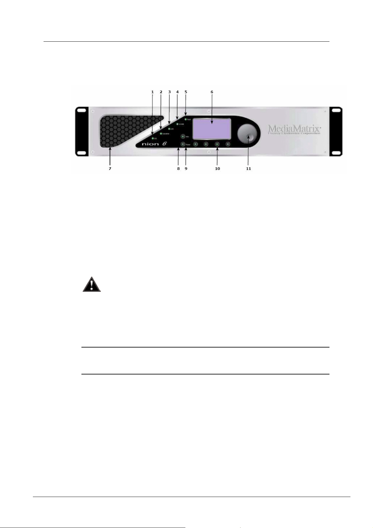
Front Panel
1. IDE Single-color LED indicates activity to/from the internal IDE storage media.
2. CobraNet Single-color LED indicates activity to/from the internal CobraNet audio
transport.
3. LAN Single-color LED indicates activity to/from the Ethernet network interface.
4. XDAB Single-color LED indicates activity to/from the XDAB audio expansion bus.
(NION n3, n6 only.)
5. Fault Single-color LED indicates muted audio condition.
6. LCD Display Backlit graphical display provides access to system hardware monitoring,
configuration and status functionality. (NION n3, n6 and nX only.)
7. Air Vent Air intake vent provides fresh air flow to internal cooling system.
Do not block or obstruct this vent. Proper airflow must be maintained for proper
operation.
8. ATTN Button includes a red LED that flashes when user response is required.
Upon pressing, LCD will then jump directly to the LCD screen that will show the error.
(NION n3, n6 and nX only.)
9. Power Button will start the boot up process when in standby mode. When the unit is
running, the button will cause the LCD screen to jump directly to the Power menu, where
you can choose to Power Down or Reboot.
Note: There is an intentional delay after powering off and before the Power button will
turn on the unit. This is meant to protect the circuitry by allowing voltages to fully
discharge. The integrated LED will not illuminate.
10. Soft Buttons (4). Momentary buttons used in conjunction with the LCD display allow
user input and navigation of hardware functionality. The function of each button is
indicated on the display text of the LCD display graphic nearest the corresponding button.
The integrated LEDs will not illuminate. (NION n3, n6 and nX only.)
11. Data Wheel Continuous action rotary encoder and embedded push-button provide
navigation and data entry functionality in conjunction with the LCD display. The function
of these controls is dependent on the active function of the LCD display. (NION n3, n6
and nX only.)
22 Version 1.6.1.0 September 30, 2010
Page 27
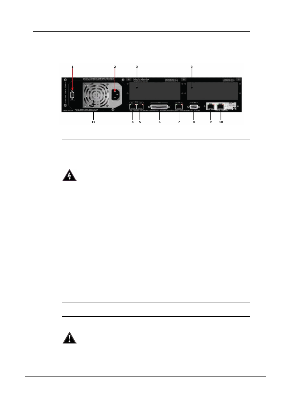
Rear panel
1. Serial Port Female DB-9 panel connector, which provides RS-232 communications for
external control protocols.
Note: On earlier units, this connector is on the front panel.
2. Power Receptacle Flush-mount IEC power receptacle for connecting a compatible IEC
power cable (included).
NION Hardware Manual
Use only the supplied cable or an equivalent international version.
3. Module Bays Housing bays for NION series expansion cards. Up to 4 Nio series I/O cards
can be installed in a NION n3 or NION n6. Up to 2 Nio series I/O cards can be installed in
a NION nX.
4. XDAB In RJ-45 panel connector accepts a shielded CAT6 data cable for transport of the
proprietary NION digital audio input bus. (NION n3, n6 only.)
5. XDAB Out RJ-45 panel connector accepts a shielded CAT6 data cable for transport of the
proprietary NION digital audio output bus. (NION n3, n6 only.)
6. GPIO Female DB-25 panel connector provides access to the internal GPIO control
functionality.
7. LAN RJ-45 panel connector accepts a CAT5 data cable for data transport to/from the
internal network interface. This connection is required on all units for system
configuration and inter-unit communications.
8. RS-485/422 Female DB-9 panel connector accepts a standard DB-9 connector (not
included) to provide access to the external RS-485 or RS-422 external control protocols.
9. CobraNet Primary RJ-45 panel connector accepts a CAT5 data cable for data transport
to/from the integrated CobraNet audio transport network interface.
10. CobraNet Secondary RJ-45 panel connector accepts a CAT5 data cable for data transport
to/from the secondary integrated CobraNet audio transport network interface.
Note: This port does not provide additional CobraNet capacity and only becomes active in
the event that the network connected to the Primary CobraNet port becomes inoperative.
11. Power Supply Industrial ATX format power supply with exhaust fan.
Additional air flow is provided on the side panel opposite the power supply. Install
with at least 2” of free clearance on sides of unit. Do not block any air intake or
exhaust vent.
September 30, 2010 Version 1.6.1.0 23
Page 28

Chapter 4 - Introduction to NION
24 Version 1.6.1.0 September 30, 2010
Page 29

Chapter 5
Setting up the NION
In This Chapter
Introduction ....................................................................................................... 26
Configuration .................................................................................................... 27
Updating the firmware ...................................................................................... 28
Using the front panel ......................................................................................... 28
Using the web interface .................................................................................... 36
September 30, 2010 Version 1.6.1.0 25
Page 30

Chapter 5 - Setting up the NION
So me text to force a page break in W ord but remain invisible
Introduction
Although there are many variables that exist for properly configuring the NION to pass audio,
the most basic requirements are shown below. These basic parameters will ensure that you can
connect, pass audio and control the NION processor.
Before you can get audio to pass through the NION, you will need to design your project file in
the NWare software. Please refer to the NWare User Guide for more information. It is highly
recommended that this process be deferred to system designers, engineers or technicians who
have attended the NION Technology & Applications Factory Seminar.
To properly configure the NION for audio operation, the following items are required or
recommended:
NION processing node
At least one Nio series analog audio input card
At least one Nio series analog audio output card
Tip: The nio-4x4 card supports both analog audio inputs and outputs on the same card.
This card can be used in place of an input card and an output card.
A late model computer running Windows 2000/XP/Vista
NWare software
Properly configured NWare project file
One Ethernet 100Base/TX network switch
At least two CAT5 cables
Audio source
Powered loudspeaker
Audio cabling.
For the purposes of testing and establishing basic operation, configure the NION as a
stand-alone processor. Typical connections for this configuration are shown in the illustration.
26 Version 1.6.1.0 September 30, 2010
Page 31

So me text to force a page break in W ord but remain invisible
Configuration
When you have established typical connections and are ready to load your NWare project file,
you should firstly configure the NION’s basic operational parameters. Certain functions, such
as communications, may not function correctly until properly configured. The configuration
process can be completed using the NION front panel interface or the web interface.
Note: If you are using a NION nE, you must use the web interface.
The front panel interface
The front panel interface includes an LCD display, four context-sensitive soft buttons, two
fixed function buttons and a data wheel with integrated push button. Basic navigation is
accomplished with the soft buttons and the wheel, while the wheel’s push button is used to
select and confirm settings. Each section of the NION interface includes several pages. Each
page is accessible in sequence, controlled by PREV and NEXT soft buttons. To complete an
entry use the OK soft button. To cancel out completely, use the CANCEL soft button. Once a
page is selected, the wheel and wheel push button will provide the navigation.
NION Hardware Manual
The cursor type indicates the action and position. An outlined cursor indicates the current
cursor position. A solid filled cursor indicates a selection. Once a cursor position is selected,
the wheel provides the ability to change the value at the current position. Pressing the wheel
button again returns the cursor to position status.
The sections that follow describe how to change settings in the CONFIG menu. This menu is
available from the Home page.
Tip: If you are viewing a different screen, you can select the HOME option to return to the
home page.
Note: If security has been enabled, you will need to specify a password before you can change
any of the settings.
September 30, 2010 Version 1.6.1.0 27
Page 32

Chapter 5 - Setting up the NION
Updating the firmware
Firmware on NIONs is managed centrally using NWare. For information on updating
firmware, see Updating firmware on MediaMatrix devices in the NWare User Guide.
Using the front panel
Setting the IP address
DHCP versus static IP
Notes:
Care should be taken when choosing to use Dynamic Host Configuration Protocol
(DHCP), rather than a static IP address. DHCP mode is provided as a convenience when
using units in informal settings or for test purposes. A static IP address should always be
used when units are deployed in end-user installations. DHCP-obtained IP addresses
depend on a lease to be maintained by the DHCP server in order to keep an assigned IP
address. If the IP address lease is allowed to expire, there is a chance that the IP address
assigned to one or more units could be lost, changed or reassigned, resulting in the loss of
control or audio from a project.
The network administrator should be able to give you a range of static (or fixed) IP
addresses to use for your project. When requesting these IP addresses, be sure to obtain
enough to cover each unit.
Using DHCP to assign an IP address automatically
1. Confirm that the network to which you are connecting the unit has a DHCP server.
Notes:
If DHCP mode is selected, but there is no DHCP server on the network, the unit will be
unable to communicate with other devices.
In this example, the DHCP server is provided by the router. Ensure that your network
is using a router. A plain switch will not provide the required DHCP server for the
example.
2. From the main menu, select CONFIG to display the first configuration page, LAN
CONFIG.
3. Move the cursor to the second line, next to IP.
4. Push the wheel button, then move the wheel until the cursor position indicates DHCP,
then push the wheel button again to confirm the settings.
28 Version 1.6.1.0 September 30, 2010
Page 33

NION Hardware Manual
Tips:
Since we are using DHCP, we do not need to specify an IP address, subnet mask or
gateway - they are automatically assigned by the DHCP process.
If a DNS is set up on the network and DHCP has been configured to contact the DNS,
the DNS field will be populated automatically with the IP address of the DNS. NION
uses the DNS to resolve the domain names of time servers. For more information, see
Setting up a NION as a master.
5. Select NEXT to advance to the next page, or OK to confirm the settings and exit.
To abort the process, select CANCEL.
Using a static IP address
1. From the main menu, select CONFIG to display the first configuration page, LAN
CONFIG.
2. Move the cursor to the second line, next to IP.
3. Push the wheel button, then move the wheel until the cursor position indicates STATIC
IP, then push the wheel button again to confirm the settings.
4. Use the wheel and wheel button to specify an IP address.
Note: The IP address must be unique on the network to avoid conflicts.
5. Set MASK to the network mask for your network.
6. If your subnet is connected to a router and this NioNode will be connecting to devices
across the router, set GATEWAY to the router's IP address.
If you have no router, set GATEWAY to 0.0.0.0.
Tip: The DNS field is used for contacting a DNS on the network, which in turn is used to
resolve domain names of time servers. For more information, see Setting the time and date
(on page 36).
7. Select NEXT to advance to the next page, or OK to confirm the settings and exit.
To abort the process, select CANCEL.
September 30, 2010 Version 1.6.1.0 29
Page 34

Chapter 5 - Setting up the NION
So me text to force a page break in W ord but remain invisible
Specifying the CobraNet settings
CobraNet is an important component of system design with NION products. In order to ensure
proper operation of the CobraNet audio transport, several variables must considered.
The NION is shipped with a default CM-1 setting of 0.0.0.0, which means that the IP will be
set only when the CobraNet Discovery application assigns it. For any other use of TCP/IP with
a CM-1, you must configure the IP address and mask.
For typical audio transport, it is generally not necessary to configure the CobraNet node with
an IP address. However, because the CM-1 supports SNMP, configuration of the IP address
and mask may be required.
To specify the CobraNet settings
1. From the main menu, select CONFIG to display the first configuration page, LAN
CONFIG, then select NEXT repeatedly until the CM-1 NETWORK CONFIG page is
displayed.
2. For DHCP operation, use the wheel and the wheel push button to set the IP address to
0 0 and the mask to 255 255 255 0.
For fixed IP operation, use the same process to configure the IP address and mask as
required by your network.
0 0
3. Select NEXT to advance to the next page, or OK to confirm the settings and exit.
To abort the process, select CANCEL.
Setting up the network services
Introduction to network services
Web
The NION processor includes a built-in web server that provides access to several key
hardware functions from any web browser. For more information about web services, please
see the NWare help file.
Telnet
Telnet is a communications protocol that provides access to the Linux system kernel on the
NioNode.
Note: For security reasons, you should only enable the Telnet function when asked to by
MediaMatrix Technical Support. Once you have finished communicating with the NION, you
should disable the Telnet function. Telnet is not required for communications with the NWare
software or for using RATC.
30 Version 1.6.1.0 September 30, 2010
Page 35

SNMP
Simple Network Management Protocol is a network protocol that provides robust monitoring
and control of system parameters across the network. Using SNMP, you can utilize a host of
standard software tools and third-party systems to extend the control and monitoring power of
the NION for a wide variety of applications.
Enabling or disabling services
The NETWORK SERVICES page provides access to global network services. Each control
is a two-state control where the service is either on (ENABLED) or off (DISABLED).
To enable or disable services
1. From the main menu, select CONFIG to display the first configuration page, LAN
CONFIG, then select NEXT repeatedly until the NETWORK SERVICES page is
displayed.
NION Hardware Manual
2. Use the wheel and wheel push button to enable or disable each service as required.
3. When you are satisfied with the services settings, select APPLY and press the wheel
button to complete the adjustment.
Configuring security
You can prevent users from controlling the NION via the front panel by enabling security and
then selecting the LOCK option from the main menu.
When security is enabled, the user must enter a four digit numeric password (called a
combination) before they can access any settings.
Caution: The FRONT PANEL COMBO feature will secure the NION from front panel
access. A lost combination cannot be retrieved and there is no back door. If the combination is
lost, the NION must be reset to a virgin state, thereby discarding any resident audio
configuration files. Use the FRONT PANEL COMBO and LOCK features with care.
Enabling security
1. From the main menu, select CONFIG to display the first configuration page, LAN
CONFIG, then select NEXT repeatedly until the FRONTPANEL COMBO page is
displayed.
September 30, 2010 Version 1.6.1.0 31
Page 36

Chapter 5 - Setting up the NION
2. Using the wheel and the wheel push button, move the cursor to each NEW COMBO field
and select a number to specify the new combination.
3. Move the selection to APPLY and press the wheel push button.
Locking the front panel
1. From the main menu, move the cursor to the LOCK icon and use the wheel push button to
enter the LOCK screen.
2. Use the wheel and the wheel push button to enter the combination.
3. Move the cursor to LOCK and push the wheel’s push button to engage security, or select
CANCEL to abort the process.
Caution: Once the front panel is locked, it will not be possible to use the functions of the
NION until the correct combination has been entered. There is no back door.
32 Version 1.6.1.0 September 30, 2010
Page 37

NION Hardware Manual
So me text to force a page break in W ord but remain invisible
Disabling security
1. From the main menu, select CONFIG to display the first configuration page, LAN
CONFIG, then select NEXT repeatedly until the FRONTPANEL COMBO page is
displayed.
2. Using the wheel and the wheel push button, move the cursor to each OLD COMBO field
and select a number to specify the current combination.
3. Move the cursor to each NEW COMBO field and select
4. Move the selection to APPLY and press the wheel push button.
5. Select HOME to return to the main page.
0 0 0 0 as the new combination.
Changing the security combination
1. From the main menu, select CONFIG to display the first configuration page, LAN
CONFIG, then select NEXT repeatedly until the FRONTPANEL COMBO page is
displayed.
2. Using the wheel and the wheel push button, move the cursor to each OLD COMBO field
and select a number to specify the current combination.
3. Move the cursor to each NEW COMBO field and select a number to specify the new
combination.
4. Move the selection to APPLY and press the wheel push button.
September 30, 2010 Version 1.6.1.0 33
Page 38

Chapter 5 - Setting up the NION
So me text to force a page break in W ord but remain invisible
Enabling or disabling the web interface
The web interface is disabled by default on NioNodes and must be enabled before you can
access a NION via a web browser.
To enable or disable the web interface
1. Open a browser and specify the IP address of the NION in the Address bar.
2. From the main menu, select CONFIG to display the first configuration page, LAN
CONFIG, then select NEXT repeatedly until the NETWORK SERVICES page is
displayed.
3. Use the wheel and the wheel push button to change the WEB setting to ENABLED or
DISABLED.
4. Select APPLY.
When the web interface is enabled, you can enter the IP address of the unit into your web
browser to get to the web interface.
Tip: If this does not work, you may have an IP address problem on either the NioNode or your
PC. If you have a proxy server set up in your internet options, you may have to create an
exception for local IP addresses.
Understanding the system status page on the front panel
The system status page on the NION front panel shows information about the CPU load during
set periods of time. The information is based on the output from the Linux Top command,
/proc/loadavg file and the uptime command.
LOAD The average of the number of tasks
running during the period of time since the
page was last refreshed.
5M Average CPU load over the last 5 minutes.
15M Average CPU load over the last 15
minutes.
CPU Current percentage utilization of the CPU.
For more information on the Top command, see
http://linux.die.net/man/1/top http://linux.die.net/man/1/top.
For more information on the /proc/loadavg file and the uptime command, see to
www.luci.org http://www.luci.org/luci-discuss/200210/ms
34 Version 1.6.1.0 September 30, 2010
g00055.html.
Page 39

Adjusting the LCD backlight intensity and viewing angle
The LCD CONFIG page allows you to adjust the LCD backlight intensity and the viewing
angle.
The perceived contrast is dependent on the viewing position. For example, a setting that
provides high contrast when viewing the display from the front, may provide an inverted view
when looking at the display from above. Adjust for the best view at the common working
angle.
To adjust the LCD backlight intensity and viewing angle
1. From the main menu, select CONFIG to display the first configuration page, LAN
CONFIG, then select NEXT repeatedly until the LCD CONFIG page is displayed.
2. Use the wheel and push button to select LCD BACKLIGHT.
NION Hardware Manual
3. Use the wheel’s rotary control to select the desired value.
The range is 0 (least intense) to 15 (most intense).
4. Use the wheel and push button to select VIEWING ANGLE.
5. Use the wheel’s rotary control to select the desired value.
The range is 10 to 40 with the 20 position providing the highest contrast and color when
viewing the display head on or directly in front.
6. When you are satisfied with the display settings, select NEXT to advance or HOME to
complete the adjustment.
September 30, 2010 Version 1.6.1.0 35
Page 40

Chapter 5 - Setting up the NION
So me text to force a page break in W ord but remain invisible
Using the web interface
Setting the time and date
Introduction
For accurate reporting of events when running different MediaMatrix units, it is critical to
specify the proper time zone, time, and date settings. Correct settings will ensure that the event
logs and other time sensitive information are accurately recorded and displayed.
There is a time synchronization system that ensures that the time and date settings on NIONs,
nControl units and nTouch 180 units are the same across the network. If you change the date
on a NION, for example, it is automatically changed on the other devices. This feature is
especially useful for debugging. If you look at an event in the log that occurred at a particular
time on one NION, you can be sure that an event with the same timestamp on a different NION
occurred at exactly the same time.
You can specify the time and date settings manually, or they can be obtained automatically
from a time server.
Tip: A time server can be set up on your local network, or you can connect to one via the
internet. For information on available internet time servers, see http://www.pool.ntp.org
(http://www.pool.ntp.org).
Synchronization modes
Mode name Description
Normal If you specify Normal mode for all units on the network, so no Master node is
available, when you specify time and date settings on any of the units, they
will be assigned to the others automatically.
If a unit on the network is using Time Server or Master mode, all units in
Normal mode will be assigned time and date settings from that unit – they
will act as slaves.
Master
Time Server This node will contact a time server to retrieve time and date settings. The
The time and date settings from this unit will be assigned to all units that are
using Normal mode.
time and date settings from this unit will be assigned to all units that are using
Normal mode.
The time server can be contacted using its IP address or a domain name.
Note: When you use a domain name, it must be resolved to an IP address.
This is done automatically, but you must specify DNS or DHCP settings on
the Network screen in the web interface.
36 Version 1.6.1.0 September 30, 2010
Page 41

NION Hardware Manual
So me text to force a page break in W ord but remain invisible
Setting up synchronization
Scenario Actions to take
You want to be able to set the time
and date on any MediaMatrix node on
the network manually, and for the
settings to then be automatically
assigned to the others.
On all MediaMatrix nodes:
1. Navigate to the Time and Timezone tab.
2. Clear the Time Server box.
3. In the Authority list, click normal.
4. Click Set.
If you want to adjust the time and date, perform these
steps on any MediaMatrix node:
1. In the Time (24hr) box, type the new time in the
format HH:MM:SS.
2. In the Date (mm/dd/yy) box, type the new date
in the format mm/dd/yy.
3. Under the Date (mm/dd/yy) box, click Set.
4. If you are using a NION, under Timezone,
specify a continent and country.
5. If the country has more than one time zone, in the
Zone list, click the time zone.
Tip: Where a country has only one time zone,
you do not need to make a selection.
You want the time and date for all
nodes on the network to be obtained
automatically from a single, master
unit.
You do not want anyone to be able to
assign times and dates to the other
units by accessing them directly.
You will specify the time manually.
6. Under the Zone box, click Set.
On the master node:
1. Navigate to the Time and Timezone tab.
2. Clear the Time Server box.
3. In the Authority list, click Master.
4. Click Set.
If you want to adjust the time and date, perform these
steps on the master node:
1. In the Time (24hr) box, type the new time in the
format HH:MM:SS.
2. In the Date (mm/dd/yy) box, type the new date
in the format mm/dd/yy.
3. Under the Date (mm/dd/yy) box, click Set.
4. If you are using a NION, under Timezone,
specify a continent and country.
5. If the country has more than one time zone, in the
Zone list, click the time zone.
September 30, 2010 Version 1.6.1.0 37
Page 42

Chapter 5 - Setting up the NION
Scenario Actions to take
Tip: Where a country has only one time zone,
you do not need to make a selection.
6. Under the Zone box, click Set.
On the other (slave) nodes:
1. Navigate to the Time and Timezone tab.
2. Clear the Time Server box.
3. In the Authority list, click normal.
4. Click Set.
Note: If you try to change the time and date
settings on the slave nodes, they will
automatically change to match the settings on the
master node.
a)
You want the time and date for all
nodes on the network to be obtained
automatically from a time server.
On the master (time server) node:
1. Navigate to the Time and Timezone tab.
2. In the Time Server box, type IP address or
domain name of a time server.
Note: If you are using a domain name to contact
the time server, a DNS must be present on the
network. If a DHCP server is not available on the
network, you must specify the IP address of the
DNS on the Network page for the local area
connection you are using.
3. In the Authority list, click time server.
4. Click Set.
Note: Once you select time server mode, you
will not be able to change the time or date
settings.
On the other (slave) nodes:
1. Navigate to the Time and Timezone tab.
2. Clear the Time Server box.
3. In the Authority list, click normal.
4. Click Set.
Note: If you try to change the time and date
settings on the slave nodes, they will
automatically change to match the settings on the
time server node.
38 Version 1.6.1.0 September 30, 2010
Page 43

Copying media files to the NION
You can copy media files over to the NION using FTP and then use them in your NWare
projects. This allows you to quickly change the available media in a project. You can also
minimize the size of the NWare project file by storing your media on the NION and not in the
project file itself. You can use any FTP client to copy the files.
In order to allow files to be copied, you need to enable the FTP server on the node you are
using. This is done via the web interface. Once FTP is enabled, you can use an FTP client (or
the FTP command from a Command Prompt window) to copy files over.
Files on an nControl unit can be played using a Media Player device in your NWare design.
Files on a NION can be played using a Wave File Player device in your NWare design.
For more information on these devices, refer to the NWare Device Reference.
Notes:
It is not currently possible to view the amount of available space for storing media files.
When the project is deployed, media files must be located on the same node that hosts the
NWare device playing the files. If the files are located on a different node, you will not be
able to play them. We recommend that you manually assign the device playing the files to
a role and deploy that role to the node that will host the media files.
You can disable the FTP server by clearing the FTP check box (see procedure below), but
if you are using an nControl unit or nTouch 180 unit, you must restart it before the change
will take effect.
NION Hardware Manual
To enable the FTP server
1. Navigate to the Network screen.
2. Under Services, select the FTP check box.
3. Click Set to confirm the action.
You will be asked to log on.
4. Specify your username and password. The default username is superuser; it has no
password.
To copy media files to the NION
1. Open a Command Prompt window.
2. Navigate to the folder containing the media files.
3. Type
4. Type
FTP and press Enter.
ftp> prompt is displayed.
The
open <IP address of NION> and press Enter.
The following message is displayed.
Connected to <IP address>.
...
User (<IP address>:(none)):
5. Type anonymous and press Enter.
6. If you are prompted for a password, press Enter.
You do not need to specify a password.
7. If you want to list the files already copied to the unit, type
September 30, 2010 Version 1.6.1.0 39
ls and press Enter.
Page 44

Chapter 5 - Setting up the NION
8. Type binary to switch to binary copy mode.
9. Type
mput <filename> and press Enter.
The parameter <filename> is either a single file or a wildcard referencing multiple files.
When you have finished copying files, type
Managing users
Introduction
Users are created via the web interface, and assigned privileges to allow them to perform
certain operations, as listed below.
Privilege What it controls
Deploy Determines whether the user can deploy a role to this node.
Update Firmware Determines whether the user can update the firmware on this
Debug Menu Access Determines whether the user can access the debug menu of
User Administration Determines whether the user can create, edit and remove user
NioNode Administration
Access
quit to close the ftp session.
node.
this node using the Pandebug application.
accounts on this node.
Determines whether the user can change settings such as
network configuration and time and date.
Log Access Determines whether the user can view or clear the log.
Tip: For more information on viewing the log within NWare,
see Remote Log in the NWare User Guide.
There are two default users: superuser and defaultuser, which cannot be deleted. You can
add your own users as necessary.
superuser Has all privileges enabled. None of its settings can be
changed, apart from the password, which is blank by default.
defaultuser Has all privileges enabled, apart from User Administration
and NioNode Administration Access.
In NWare, when you perform an action that involves the node, such as deploying a role or
updating firmware, NWare logs on to the node using a particular username. The node matches
this username with the username of the same name stored on the unit. The privileges of the
username on the node determine whether the action may be carried out.
Tip: Users often log on to nodes with the username defaultuser. If the settings for this
username on the node show the Deploy privilege set to Disallow, it will not be possible to
deploy a role to the node even when they are logged on.
40 Version 1.6.1.0 September 30, 2010
Page 45

NION Hardware Manual
So me text to force a page break in W ord but remain invisible
Adding a new user
1. Navigate to the User Management screen in your web browser.
2. Click Add new user.
The Edit User screen is displayed.
3. In the user name box, type the name of the new user.
4. If you want to specify a password for the user, which must be specified when the user logs
on, type the password in the Password box, and then type the password again in the
Confirm box.
Note: We recommend that you always specify a password for users to ensure
unauthorized persons do not gain access to the node.
5. Specify the user privileges.
Privilege What it controls
Deploy Determines whether the user can deploy a role to this node.
Update Firmware Determines whether the user can update the firmware on this
node.
Debug Menu Access Determines whether the user can access the debug menu of
this node using the Pandebug application.
User Administration Determines whether the user can create, edit and remove user
accounts on this node.
NioNode Administration
Access
Determines whether the user can change settings such as
network configuration and time and date.
Log Access Determines whether the user can view or clear the log.
Tip: For more information on viewing the log within NWare,
see Remote Log in the NWare User Guide.
6. Click Apply.
Deleting a user
You can delete users from a node when they are no longer required.
Note: You cannot delete defaultuser or superuser.
To delete a user
1. Navigate to the User Management screen in your web browser.
2. Click the Delete button next to the user you want to delete.
You will be asked to confirm the delete operation.
3. Click Yes.
September 30, 2010 Version 1.6.1.0 41
Page 46

Chapter 5 - Setting up the NION
Managing the role
In an NWare project, devices that are part of the design are assigned to roles, either
automatically by NWare or manually by the user. Each role is then assigned to a NION,
nControl unit or nTouch 180 unit for processing when the project is deployed.
Tip: Once a project has been deployed to a node, if the node is power cycled, the project is
restarted automatically.
The Audio screen shows the NWare project to which the role belongs, the name of the role and
how long it has been loaded.
Restarting the role
1. On the Audio screen, under Role Actions, click Restart.
2. Click OK to confirm the action.
Stopping the role
1. On the Audio screen, under Role Actions, click Halt.
2. Click OK to confirm the action.
Erasing the role
1. On the Audio screen, under Role Actions, click Erase.
2. Click OK to confirm the action.
Specifying the function of the RS-232 serial port
The NION RS-232 serial port performs two main functions:
In console mode it allows a user to log on to the NION Linux Kernel via a serial terminal
session and change the configuration settings.
When console mode is disabled, you can control the NION using external protocols like
PASHA.
By default, console mode on the RS232 serial port is disabled.
To specify the function of the RS-232 serial port
1. Open a browser window.
2. Type the IP address of the NION in the Address bar, and then press Enter.
42 Version 1.6.1.0 September 30, 2010
Page 47

NION Hardware Manual
The Audio screen is displayed.
3. Click Special.
4. Click Advanced.
September 30, 2010 Version 1.6.1.0 43
Page 48

Chapter 5 - Setting up the NION
The Advanced and Debug screen is displayed.
5. Under RS232 serial port, select or clear the Console enabled check box.
6. Click Set.
You will be asked to log on.
7. Type the username and password for the superuser.
By default, the username is superuser and the password is blank.
8. Reboot the NION, so the changes take effect.
44 Version 1.6.1.0 September 30, 2010
Page 49

Chapter 6
Using XDAB clusters with VLANs
and CobraNet
In This Chapter
Introduction ....................................................................................................... 46
Important concepts ............................................................................................ 46
Use cases ........................................................................................................... 47
Setting conductor and XDAB priority in NWare .............................................. 53
Further examples ............................................................................................... 55
September 30, 2010 Version 1.6.1.0 45
Page 50

Chapter 6 - Using XDAB clusters with VLANs and CobraNet
So me text to force a page break in W ord but remain invisible
Introduction
Use of NIONs in an XDAB cluster, particularly when also using CobraNet and VLANs,
creates specific considerations and rules that must be observed in order to insure proper
operation of the system. This chapter is intended to provide awareness of the technical issues
that must be considered when using XDAB clusters and VLANs with CobraNet. A basic
knowledge of CobraNet, NIONs and VLANs is assumed.
Note: XDAB is available on NION n3 and N6 models, but not nX models.
Important concepts
XDAB cluster
NIONs connected together via XDAB are referred to as an XDAB cluster.
There is one XDAB master that provides the audio clock to all other devices in the cluster. The
other devices in the cluster are XDAB slaves.
Audio clock domain
All CobraNet devices on the same network or VLAN segment must operate within the same
audio clock domain. A system wide isochronous audio clock is automatically generated in a
CobraNet network by the standard beat packet mechanism. A NION or CAB will always
receive its audio clock from CobraNet.
Note: An exception exists for NIONs operating within an XDAB cluster:
In the XDAB master the CobraNet clock can be taken from the CobraNet network as a
CobraNet performer or the XDAB clock can be supplied as the CobraNet Conductor.
Normal CobraNet clocking concepts apply.
In XDAB slaves the CobraNet clock will always be taken from XDAB and will not be
taken from the CobraNet network audio clock directly. The clock will be taken indirectly
from CobraNet via the clock generated by the XDAB master.
Logical separation of the network
Use of VLANs creates a logical separation of the network that causes the VLAN segments to
behave as if they are physically separate networks. Use of the term VLAN also applies to
physically separate networks.
Each VLAN segment must therefore have its own CobraNet Conductor.
Multiple VLANs
Audio can be exchanged between different VLANs through the use of devices that have a
network interface on each VLAN. This can be accomplished by:
exchanging analog audio between devices. Devices connected using analog I/O do not
need to be concerned with audio clocking issues between them.
or
exchanging digital audio between devices. In this case, the audio clocks of the devices
must be synchronous or the use of sample rate converters on the digital audio inputs is
required.
46 Version 1.6.1.0 September 30, 2010
Page 51

Tip: The XDAB digital audio bus is the most convenient way to exchange digital audio
between NIONs.
NIONs on CobraNet
Notes:
Processing on a NION will pause during project deployment. Therefore, a NION that is a
Conductor will stop being the Conductor for a time. The network will then automatically
transition to a new Conductor. Conductor transitions will cause momentary audio
dropouts. It may therefore be desirable to designate a non-NION device to be the CobraNet
Conductor.
Additionally, if using XDAB, clock disruption caused by a change of Conductor may often
cause the NION cluster to re-sync (re-arbitrate) the XDAB clock and will result in a
dropout of several seconds.
Use cases
NION Hardware Manual
Scenario 1 - Basic network
In this scenario, there are:
no XDAB interconnections between NIONs.
no VLANs defined.
no outboard audio connections, either analog or digital, between NIONs.
There is only one audio clock domain in this scenario established by CobraNet and no special
Conductor, topology or XDAB usage considerations apply.
September 30, 2010 Version 1.6.1.0 47
Page 52

Chapter 6 - Using XDAB clusters with VLANs and CobraNet
Scenario 2 - Network using VLAN
In this scenario, port based VLANs have been configured within a managed switch:
There will be no audio passed, either externally or via CobraNet, between devices residing
on different VLANs.
Audio is only exchanged via CobraNet between NIONs that reside on the same VLAN.
One device on each VLAN must be a CobraNet Conductor for that VLAN, i.e. each
VLAN has its own Conductor.
It is not important, logically, which devices are chosen to be Conductors. Consideration of
Conductor location will only be determined when necessary, by standard network
topology considerations that would apply to any CobraNet network.
Scenario 3 - Network with VLAN and analog interconnects
In this scenario, VLANs are configured using the port based VLAN capability of a managed
switch.
Audio is bridged between the two VLANs using analog interconnects.
The same rules for Conductors would apply as in the previous scenario (on page 48).
The analog interconnect creates no digital audio clock domain issues.
48 Version 1.6.1.0 September 30, 2010
Page 53

Scenario 4 - Network with VLAN and digital interconnects
This scenario is similar to the previous scenario (on page 48), but substitutes digital
interconnects), such as AES/EBU or SPDI/F, for analog interconnects.
NION digital interface cards contain built-in sample rate converters (SRCs), which isolate
audio clock domains from each other and allow interchange of digital audio data
regardless of which clock domain the transmitting and sending devices are in.
VLAN 1 and VLAN 2 each have their own Conductor, so are in different audio clock
domains.
The SRC built into the digital interface card will allow exchange of digital audio between
the NIONs in the two clock domains.
Bypassing the SRC, which is possible, will cause errors on the AES/EBU interface.
NION Hardware Manual
Scenario 5 - Network with an XDAB cluster
In this scenario, digital audio is exchanged between NIONs through XDAB.
The XDAB master can be any device within the cluster.
The CobraNet Conductor can be any device outside the cluster.
Remember that all XDAB slaves and their CobraNet interfaces take their clocks from
XDAB.
September 30, 2010 Version 1.6.1.0 49
Page 54

Chapter 6 - Using XDAB clusters with VLANs and CobraNet
An XDAB master that gets its clock as a CobraNet performer that is synched to a
Conductor that is in turn an XDAB slave would create an unstable clock resolution loop.
XDAB would attempt to sync with CobraNet that would in turn be trying to sync with
XDAB.
The XDAB master and CobraNet Conductor will both be in the same NION automatically
when default settings are used. If default settings are changed, then be sure to set the
XDAB priority and CobraNet Conductor priority to insure that a single NION is both the
XDAB master and CobraNet Conductor.
Notes:
If the Conductor is placed within the cluster, then it must also be in the same NION as the
XDAB master. If you increase the Conductor priority for one of the NIONs, you must also
increase its XDAB priority to insure that the Conductor and XDAB master will stay in the
same NION.
If a Conductor for a CobraNet network is placed within an XDAB cluster, the NION
containing the Conductor must also be the XDAB master.
Scenario 6 - Network with VLAN and XDAB
In this scenario, the network is divided into VLANs and an XDAB cluster is used. Two
VLANs are shown; more are possible.
XDAB is used to pass digital audio between NIONs within a cluster and therefore between
VLANs.
VLANs logically become one of two types in this scenario:
A master VLAN, i.e. the VLAN in which the XDAB master resides.
A slave VLAN, i.e. all other VLANs in the cluster.
The Conductor on the one master VLAN must be either:
completely outside the XDAB cluster
or
must also be the XDAB master.
The same caveats regarding Conductor location as described in the previous scenario (on
page 49) must be observed. But it is also important to properly locate the CobraNet
Conductors for the slave VLAN (VLAN 2) to be sure that a clocking conflict is not created
between XDAB and VLAN 2’s CobraNet clock.
50 Version 1.6.1.0 September 30, 2010
Page 55

Regardless of whether the VLAN 1 Conductor is inside or outside of the cluster, all
NIONS in the cluster that are in VLAN 2 will be getting their clock from XDAB and
cannot receive their clock from an outside Conductor. This would create a clocking
conflict.
Therefore, the Conductor for VLAN 2 must be located within the XDAB cluster, as
shown.
Scenario 7 - Network with VLAN and XDAB
NION Hardware Manual
This scenario is a variant of the previous scenario (on page 50).
The Conductor for VLAN1 is outside the XDAB cluster. This will still work.
The CobraNet interface in the XDAB master will sync to the Conductor outside the
cluster. That clock will become the XDAB master clock. XDAB and VLAN 1 will be in
sync.
However, the Conductor for VLAN 2 must still remain within the cluster because all
XDAB slaves in a cluster will receive their clock from XDAB and not from CobraNet.
Placement of VLAN 2’s Conductor outside the cluster will cause the XDAB clock and
externally sourced VLAN 2 CobraNet clock to be in conflict.
Scenario 8 - Network with VLAN and two XDAB clusters
September 30, 2010 Version 1.6.1.0 51
Page 56

Chapter 6 - Using XDAB clusters with VLANs and CobraNet
This scenario is a variant of the previous scenario (on page 51), but contains more than one
XDAB cluster.
The same rules apply as in the previous scenario.
Again, the Conductor for VLAN 2 must be within the XDAB cluster.
It does not matter which cluster the Conductors are in. In this case, the Conductors are
show in cluster 1.
In this example, it does not matter which device in cluster 2 is the XDAB master. The
XDAB master will receive its audio clock from a CobraNet Conductor in either VLAN 2
or VLAN 1, both of which are in sync with each other.
The clock received by any device in cluster 2 via CobraNet will be the same because the
Conductors for both VLANs are in cluster 1 and are synched to the same clock.
Scenario 9 - Network with VLAN and three XDAB clusters
In this scenario, there are three VLANs, three XDAB clusters and no cluster contains all three
VLANs.
In cluster 1, VLAN 1 contains the XDAB master.
In cluster 1, VLAN 2 receives its clock from XDAB and is therefore in sync with VLAN 1.
In cluster 2, VLAN 1 is the XDAB master and receives its clock from the VLAN 1
Conductor in cluster 1.
In cluster 2, VLAN 3 receives its clock from XDAB. This clock is derived from the
Conductor of VLAN 1.
In cluster 2, one of the devices in VLAN 3 is the Conductor for VLAN 3.
In cluster 3, VLAN 3 is the XDAB master and receives its clock from the Conductor in
VLAN 3 in cluster 2.
In cluster 3, VLAN 2 is receiving its clock from the XDAB master in VLAN 3.
All Conductors in this topology are ultimately deriving their clocks from the Conductor
and XDAB master in VLAN 1 of cluster 1. So all clocks in this network in all three
VLANs will be in sync. No clock conflicts will exist.
52 Version 1.6.1.0 September 30, 2010
Page 57

Setting conductor and XDAB priority in NWare
Introduction
You can use NWare to change the CobraNet Conductor and XDAB master priorities. These
settings will ensure that a particular device within an XDAB cluster will become the XDAB
master or that a particular CobraNet device on a network or VLAN segment will become a
CobraNet Conductor.
Each NION will set the actual priority from within the range specified by the user. Each of
these ranges can have two values.
If you want a NION to be an XDAB master or a CobraNet Conductor, set the appropriate range
to be higher than any other device in the cluster.
Notes:
NWare will normally ensure that the default values are set for proper operation. However,
it may be necessary to manually adjust the settings in order to meet the constraints outlined
in the use cases (on page 47).
Be aware of the Conductor priority settings of devices outside the XDAB cluster that
reside elsewhere on the network. This point is important when using slave VLANs in order
to insure that a slave device within a cluster remains the CobraNet Conductor.
NION Hardware Manual
Tips:
Explicitly set the CobraNet Conductor priority and XDAB master priority in all devices to
insure they operate correctly.
Locate the CobraNet Conductor outside an XDAB cluster when possible.
Set all Conductor priorities to 0 in all devices except those that should be allowed to be
Conductors. For those devices that should be Conductors, make their priorities the same.
Devices with CM-1 modules are preferred as Conductors over devices that have CM-2
modules.
September 30, 2010 Version 1.6.1.0 53
Page 58

Chapter 6 - Using XDAB clusters with VLANs and CobraNet
So me text to force a page break in W ord but remain invisible
Adjusting the CobraNet Conductor and XDAB clock master priorities
1. Right click on the NION on the NWare page, and then click Device Properties.
The NioNode Properties dialog box is displayed.
2. Click Advanced.
The Advanced properties dialog box is displayed.
3. In the CobraNet Conductor Priority list, click the priority range for the NION.
4. In the XDAB Clock Master Priority list, click the priority range for the NION.
Tip: If you want a NION to be an XDAB master or a CobraNet Conductor, set the
appropriate range to be higher than any other device in the cluster.
54 Version 1.6.1.0 September 30, 2010
Page 59

Further examples
Worked example 1 - follow the clock
An XDAB master NION will always receive the audio clock from its CobraNet module,
regardless of whether that module is a Conductor or a performer.
If the CobraNet clock source is external to the cluster (i.e. the XDAB master is a performer
and the Conductor is external to the cluster), it will still work fine.
If the clock source is internal to the cluster (i.e. the CobraNet Conductor is within the
VLAN within the cluster), then the XDAB master and the CobraNet Conductor must be
the same.
NION Hardware Manual
Notes:
In the example above, the clock source is the CobraNet Conductor (clock path 1). This
Conductor NION must also be the XDAB master. Clock 1 will be transmitted by XDAB to
the other devices in the cluster and also to the other cluster on the network via CobraNet.
In Cluster 2, the XDAB master is a performer.
September 30, 2010 Version 1.6.1.0 55
Page 60

Chapter 6 - Using XDAB clusters with VLANs and CobraNet
So me text to force a page break in W ord but remain invisible
Worked example 2 - a bad configuration
The Conductor for VLAN 1 is the second device in the VLAN 1 segment within XDAB
Cluster 1. It is therefore the clock source for VLAN 1 (clock path 1).
The XDAB master in Cluster 1 is therefore a CobraNet performer in VLAN 1.
The audio clock will originate in the Conductor from which the XDAB master (a
performer) will get its clock via CobraNet.
The performer, XDAB master, will then supply its clock to the XDAB chain (clock path 2)
from which the Conductor will get its clock.
A clock loop exists in this example.
The XDAB master is relying on the CobraNet Conductor for its clock source, delivered to
it via CobraNet., but the CobraNet Conductor is relying on the XDAB master for its clock
source delivered to it via XDAB.
Both devices consider the other one to be their clock source and so neither can provide a
stable clock to the other.
Clock Path 1 is a CobraNet clock distributed on the network and is an unstable clock for
reasons outlined above. Therefore, the audio clock in cluster 2, which is received on clock
path 1 and propagated via XDAB to the other devices in the cluster, will also be unstable.
No device in Cluster 1 or Cluster 2 will have a stable audio clock.
Note: It may be possible for the two clocks (XDAB master and Conductor in cluster 1) to
become stable and synchronous. But this will be a time consuming matter of chance, rather
than a deterministic certainty, as the XDAB chain attempts to arbitrate a master. In the
absence of any beneficial timing coincidences at the beginning of a sync attempt, the
clocks would never sync up.
56 Version 1.6.1.0 September 30, 2010
Page 61

Appendix A
Troubleshooting
In This Appendix
Cannot access NION using IP address or IP address is unknown .................... 58
Front panel LED indicators ............................................................................... 59
Enabling error logging ...................................................................................... 61
HF2 errors ......................................................................................................... 62
Low voltage warning ........................................................................................ 66
NION locking up or rebooting spuriously ........................................................ 66
September 30, 2010 Version 1.6.1.0 57
Page 62

Appendix A - Troubleshooting
So me text to force a page break in W ord but remain invisible
Cannot access NION using IP address or IP address is unknown
This section explains how to connect to a NION directly via the serial port and change the IP
address settings. This is only necessary under the following circumstances:
The NION does not appear on the Remote Log tab in NWare and Pandad is functioning
(i.e. other NIONs on the same network are listed). If you need to check to see if Pandad has
stopped working, see Determining if Pandad has stopped functioning in the Pandad
Administrator Guide.
The NION is listed on the Remote Log tab, but when you right-click it and then click
Launch Web Interface, the web interface is not displayed.
You need to access a NION using its IP address, but the address is unknown and you are
unable to run NWare to discover all the NIONs on the network.
Caution: It is very important that you only complete the steps in this section when under
instruction from MediaMatrix Technical Support. It is possible to lose data stored on the
NION or to stop it from booting if you specify settings incorrectly.
Tip: If the NION is fitted with a front panel, you can change the IP address using the front
panel interface. For more information, see Setting the IP address (on page 28).
Tip: If the NION has been assigned correct IP settings, but you are still unable to start the web
interface, this may be because the IP address of your PC is not compatible with the IP address
of the NION. Consider changing the IP address of your PC so that it can communicate with the
NION. The format of the NION IP address will be shown in the URL used when attempting to
start the web interface.
Note: The first procedure below assumes that the key used to stop the NION boot sequence is
ESC, which is the default setting. This is specified by the bootstopkey environment variable. If
you do not know the appropriate key and are unable to stop the boot sequence, contact
MediaMatrix Technical Support.
To connect to the NION via the serial port
1. Connect a serial cable between the PC serial port and the NION RS-232 serial port.
2. Start a terminal emulator program with the following settings:
baud rate 57600
8 bit data
no parity
1 stop bit
no flow control.
3. Power cycle the NION.
4. As soon as the NION starts to boot up (and the fans can be heard), continuously press the
ESC key.
A command prompt like this => will be displayed in the console window.
58 Version 1.6.1.0 September 30, 2010
Page 63

5. Press Enter.
To specify a static IP address
1. Type setenv dhcp no and press Enter.
2. Type
3. Type
setenv ipaddr <IP address> and press Enter.
setenv netmask <subnet mask> and press Enter.
4. If you want the settings to be saved and used each time the NION boots, type
press Enter.
If you omit this step, the settings will only be used for the current session.
5. Type
To specify an IP address automatically using DHCP
boot and press Enter.
1. Type setenv dhcp yes and press Enter.
2. If you want the settings to be saved and used each time the NION boots, type
press Enter.
If you omit this step, the settings will only be used for the current session.
3. Type
boot and press Enter.
NION Hardware Manual
saveenv and
saveenv and
Some examples
Scenario Command to use
The NION is configured with a static IP
address, but you want to assign a new
address that is temporary.
You want to use DHCP for this session and
each time the NION boots.
You want to use a static IP address for this
session and each time the NION boots.
Front panel LED indicators
setenv ipaddr 10.1.10.100
setenv netmask 255.255.0.0
boot
setenv dhcp yes
saveenv
boot
setenv dhcp no
setenv ipaddr 10.1.10.100
setenv netmask 255.255.0.0
saveenv
boot
There are several LEDs on the NION front panel that help indicate unit status.
Fault
RED Audio not working.
OFF Audio working.
September 30, 2010 Version 1.6.1.0 59
Page 64

Appendix A - Troubleshooting
The Fault LED tracks the state of the fault relay. (The fault relay signals appear on pins of the
GPIO connector.)
Note: The RED state does not necessarily indicate a problem, but that audio is not actively
being processed and passed. This state occurs normally when the unit is rebooting or has not
yet been configured to run a Project. It also occurs when the unit has encountered a problem
and can no longer process and pass audio.
X-DAB
GREEN Primary and backup rings are operational.
YELLOW OR
GREEN
Running in backup with single cable missing all audio present.
BLINKING
YELLOW/RED
OR RED
Running in backup mode with multiple
cables/nodes missing - some audio gone.
BLINKING
RED Failure - some or all audio gone. Not running
in backup mode.
OFF XDAB is not in use (in the current Project/Role
for this NioNode).
Note: The XDAB LED is updated only when XDAB is used by the NioNode in the current
Project and the NioNode is up and passing audio.
LAN
GREEN Ethernet link.
OFF No Ethernet Link.
CobraNET
GREEN Ethernet link.
GREEN
BLINKING
Ethernet link and NioNode is
CobraNet Conductor.
RED No link or CM-1 missing or
malfunctioning, and NioNode
is configured to use CM-1.
OFF No link or CM-1 missing or
60 Version 1.6.1.0 September 30, 2010
Page 65

NION Hardware Manual
malfunctioning, and NioNode
is not configured to use CM-1.
Note: Even if the NioNode has not been configured to use its CM-1 (in the project design),
link and Conductor status are still reported and the unit will be visible as a CobraNet node on
the network it is attached to. You will only see RED, however, if the NioNode has been
configured to use its CM-1 and there is a problem with link or with the CM-1 module.
IDE
GREEN Mass storage (CompactFlash)
read or write activity.
OFF No activity.
Tip: The IDE LED indicator is remarkably similar to the disk status LED you may have on the
front of your PC or on the bezel of your laptop.
Attn
RED BLINKING Indicates there is an error or
warning condition of interest.
OFF No status change of interest.
Tip: This indicator is paired with a button. When the LED blinks, the button can be pressed to
cause the LCD to navigate to a page displaying the source of the condition.
Attn
OFF Unit is off.
ORANGE Unit is booting up or down.
GREEN Unit has booted up.
Enabling error logging
Before you can log and review errors that are generated on a NION, you must enable error
logging via the NION web interface and within NWare.
To enable error logging
1. In NWare, click the Remote Log tab at the bottom window.
September 30, 2010 Version 1.6.1.0 61
Page 66

Appendix A - Troubleshooting
2. In the Targets Found pane, right-click on the NioNode and then click Launch Web
Interface.
A browser will be opened displaying the home page of the selected NioNode.
3. In the browser, click Special at the top of the page.
4. At the bottom of page, Click Advanced.
5. Scroll to the bottom of the window, and then click set all.
6. Click apply.
7. Close the browser.
8. In NWare, in the Targets Found pane, right-click on the NioNode, and then click Enable
Polling.
A green check will be shown next to the NioNode to indicate that polling is enabled. Log
messages will be shown in the pane on the right. You can view the log for an individual
NioNode by clicking the node in the Targets Found pane.
HF2 errors
HF2 is the generic term for a class of errors that are caused by a communication failure
between the NION processor and CobraNet CM-1 module. This type of error may appear as
one of the following in a NION error log:
cm1 not detected : /dev/pion/cm10: timeout waiting for HF2 to go high
peek aborted after 5 tries: /dev/pion/cm10: timeout waiting for HF2 to
go high
poke/peek driver exception : /dev/pion/cm10: timeout waiting for HF2 to
go high
A hardware handshake line between the NION and CM-1 has failed to operate correctly, i.e.
the CM-1 has become unresponsive.
The causes of HF2 errors
HF2 related errors could have two basic causes:
A hardware error. The physical hardware is at fault.
The firmware running on the CM-1 has malfunctioned and cannot respond to the NION.
Case 1 - Hardware error
In this case the interface between the CM-1 and NION has failed due to a chronic hardware
problem. This condition can be identified by persistence of the error through multiple power
cycles of the NION. A hardware fault can only be remedied by repair or replacement of the
failed component. Please consult your dealer for further information regarding repair or
replacement of hardware.
A hardware error can also be caused by a NION operating at elevated temperature. Address
cooling and ventilation issues when this cause is suspected.
Case 2 - Firmware malfunction
Firmware malfunction is the primary focus of this troubleshooting section. This cause of
failure is characterized by proper operation of the NION followed by occurrence of an HF2
error. Subsequent power cycling of the NION can return the device to proper operation.
Although the root cause is a firmware problem, there are network related issues that can
stimulate the problem and steps that can be taken to mitigate it.
62 Version 1.6.1.0 September 30, 2010
Page 67

NION Hardware Manual
The CM-1 firmware, up to and including version 2.9.16, contains a bug. This bug will allow a
stack overflow to occur during times of excessive network traffic that will render the CM-1
inoperative. A fix is not currently available, but is being worked on. This problem can occur in
any CM-1 module installed in a NION, CAB or Mainframe.
Note: The CAB 4n is available with both CM-1 and CM-2 modules. Only CM-1 modules are
affected.
Verification of the problem - all conditions will be present
The CM-1 will initially work properly.
The CM-1 will become unresponsive. This can be indicated by an inability to change
bundles.
An HF2 related error will be logged.
All audio bundles in and out of the CM-1 will stop.
The CobraNet interface will not show active in CobraNet Discovery.
The LED indicators on the CobraNet RJ-45 Ethernet connectors will most likely be static
and in a random state. They will not be blinking in the normal pattern that indicates
CobraNet activity. In some cases, the lights will blink in a repeatable pattern of 7,6,2.
A hardware reset will correct the problem.
The causes of firmware malfunction
Presence of excessive network traffic, also known as a data storm, can cause a stack overflow
to occur. A data storm can be caused by the presence of a loop in the network. Loop problems
can be more acute in larger networks and in networks that contain gigabit Ethernet links. A
data storm can also be caused by malfunctioning equipment in rare cases.
Some devices will transmit multicast data in normal operation. In a large network, if many or
all devices on the net do so by coincidence at the same time, a condition similar to a data storm
can occur and have similar consequences for a brief instant.
To put it in audio terms, a network loop is analogous to an audio feedback loop. The screech
one hears in audio feedback is due to continuous positive reinforcement of the signal. A
network loop causes a similar positive reinforcement of the data. Data packets are replicated
and increase in quantity with each hop through a switch until all available network bandwidth
is consumed.
September 30, 2010 Version 1.6.1.0 63
Page 68

Appendix A - Troubleshooting
Many Ethernet switches contain some variant of the Spanning Tree Protocol (STP, RSTP or
MSTP) that detects and logically removes loops. Standard STP should not allow a connection
to be made until it is sure that the connection will not cause a loop. MSTP and RSTP can
behave a little differently. If a new connection is made through a port that the protocol
previously considered to be an edge port. (i.e. it cannot be connected to another switch), then
the port will be immediately enabled. If this connection is such that it can create a loop, then a
data storm can occur. Explicitly setting ports within an RSTP/MSTP managed switch to be
edge or bridge ports, per their usage, may alleviate this problem.
Commonly used fault tolerant techniques for CobraNet networks
Intentional creation of a loop, with reliance on STP to remove it, in order to create a spare
connection that will be automatically activated when a link in the network goes down.
Use of the primary and secondary Ethernet connections on a CobraNet interface along
with redundant and interconnected switches. Proper use of CobraNet DualLink with
redundant networks will intentionally create a loop that is automatically removed or
restored by STP.
Loop scenarios
A loop is present on the network. A number of scenarios can be seen:
The switches are powered up and stable. STP has logically removed all loops. CobraNet
devices are then powered up. No loop effects will be seen.
CobraNet devices are powered up and stable. One or more switches are powered up (or
powered down then up). A momentary data storm may occur long enough to cause CM-1
failures.
64 Version 1.6.1.0 September 30, 2010
Page 69

NION Hardware Manual
A network topology, such as either of the examples in the Commonly used fault tolerant
techniques for CobraNet networks (on page 64) section, is in use and functioning properly
with redundant links having been removed by STP. A link between switches is then
broken. STP creates a new path and the network continues to work properly. Later, the
bad link is repaired. When the link is reestablished, a loop is momentarily created until
STP removes it.
Rapid Spanning Tree (RSTP) is a newer variant of Spanning Tree (STP) in which
management of the links is accomplished an order of magnitude faster than standard
Spanning Tree. The net effect of this operating characteristic is that a network using RSTP
can experience data storm like events in the course of its normal operation while resolving
loops.
What we know
CobraNet modules can crash in the presence of excessive network traffic (data storms).
Excessive traffic is almost always caused by the presence of a loop but can, in some cases,
be a consequence of normal operation.
Loops, in conjunction with the use of Spanning Tree or an analogous feature such as
RSTP, MSTP or Meshing (a proprietary HP protocol), can be intentionally used to create
fault tolerant network topologies.
Different topologies can cause loop effects.
Loops and use of Spanning Tree will typically only apply to networks that use more than
one switch. Use of more than one switch is common.
Mitigation
Do not use topologies that intentionally employ loops when their use can be avoided.
Check for the presence of, and remove any, unintended loops.
Do not use Rapid Spanning Tree (RSTP or MSTP). Use STP.
Use switches that allow port based bandwidth throttling or data storm control. The
configuration of a throttling feature will be switch vendor specific. Configure each port
directly connected to a CobraNet device to limit the amount of traffic allowed to go from
the port to the CobraNet device.
Data storm control often consists of severely limiting or stopping multicast data. Be
sure that this feature is not configured to prevent the passage of normally occurring
multicast CobraNet data which includes beat packets, reservation packets and
multicast bundles.
A good rule is to limit traffic going to a CobraNet device to 50 megabits. Less traffic
may be acceptable and safe depending on the number of bundles and channels received
by a device. More than 50 Mbit of bandwidth will seldom be required when using
CM-1 modules.
The specific bandwidth to allow should be the amount of received data plus
approximately 10 to 15 megabits
A CM-1, when fully configured to receive 32 channels of 48 kHz sample rate audio
data at standard latency, will receive approximately 32 Mbit of audio data + beat
packets + SNMP + serial or packet bridge. The additional 10~15 Mbit is intended to
accommodate data other than audio bundles.
Additional requirements for bandwidth will be created by the use of:
Lower latencies – approx +10% per decrease in latency
96 kHz sample rate - doubles the required bandwidth per channel
Packet bridge – use dependant
Serial bridge – use dependant
September 30, 2010 Version 1.6.1.0 65
Page 70

Appendix A - Troubleshooting
SNMP – use dependant.
Best practices
Explicitly set the CobraNet Conductor priority and XDAB master priority in all devices to
insure they are set correctly.
Locate the CobraNet Conductor outside an XDAB cluster when possible.
Set all Conductor priorities to 0 in all devices except those that should be allowed to be
Conductors. For those devices that should be Conductors, make their priorities the same.
Devices with CM-1 modules are preferred as Conductors over devices that have CM-2
modules.
Low voltage warning
When using phantom power for high current draw condenser mics on NIONs, and when all
four I/O slots are populated with ML II cards, the +/-24V power voltage may drop a little. This
is because on some NIONs, the 24V power supply current limit is slightly low. This voltage
drop is sometimes sufficient to trigger the voltage warning: the Attn button on the front of the
NION will flash red, and pressing it will bring up the voltage monitoring screen, with the
+/-24V measurements highlighted.
Under most conditions, the voltage drop will not have any effect on the functioning of the
NION, because the full 24V is actually substantially more than the cards require. The 24V
supplies feed local regulators on the cards which generate a substantially lower voltage for the
analogue i/o circuits - this decouples the analogue circuitry from variations in the 24V supply.
The problem can be worked around by using less power hungry microphones or by removing
one of the ML II cards from the unit. If you cannot do this, contact your local NION service
agent.
NION locking up or rebooting spuriously
If you load a role onto a NION and find that the unit has locked up, or keeps rebooting
spuriously, it may not be possible to erase the role via the front panel or the web interface using
the normal methods.
The NION includes a service menu, accessible at boot time, which will allow you to boot the
unit, but not load the role. It can then be erased.
Caution: It is very important that you follow the instructions in this section carefully. Do not
experiment with other options in the service menu. You could make the NION inoperable.
To stop the role from loading automatically at boot time
1. Switch off the NION by pressing the Power button, and then selecting OK.
2. Hold down the two buttons indicated below.
66 Version 1.6.1.0 September 30, 2010
Page 71

NION Hardware Manual
3. While holding down the buttons, press the Power button to switch the NION back on.
This menu will be displayed.
OPTIONS:
> WHEEL TO EDIT
> ATTN TO BOOT
UPDATE MEDIA
4. Turn the wheel clockwise until BOOT MODE is displayed.
5. Push the wheel button.
6. Turn the wheel to select QUIET, then push the wheel button to select the option.
7. Press Attn.
The NION will boot. You will then be able to erase the role without running it.
8. Reboot the NION.
The NION will start in NORMAL boot mode.
September 30, 2010 Version 1.6.1.0 67
Page 72

Page 73

Appendix B
Connector ports
In This Appendix
Audio connections ............................................................................................ 70
CAT 5 connections ........................................................................................... 70
GPIO overview ................................................................................................. 71
Serial communications ...................................................................................... 75
XDAB communications .................................................................................... 78
September 30, 2010 Version 1.6.1.0 69
Page 74

Appendix B - Connector ports
So me text to force a page break in W ord but remain invisible
Audio connections
Each audio connection on the CAB and NION products is a single, three-wire, balanced
analog circuit. The connections are identical for both microphone, line input and line output
connections. We recommend that audio connections are made with high quality shielded wire.
Note: As with any electronic connection, care should be taken to ensure that the termination is
solid. There should be no stray wire strands, kinks or nicks in the wire jacket for a proper
termination.
CAT 5 connections
Category 5 cable, or CAT 5 as it is commonly known, is a wiring standard that consists of 8
conductors, identified into 4 pairs, and although only two of these pairs are used, all four are
terminated.
It is a UTP (Unshielded Twisted Pair) configuration. The cable is coupled to in-line RJ-45
connectors, also a Bell/AT&T standard. Special crimping tools are required to make the
termination; these are widely available, as are the connectors.
Just like telco wire, there are stranded and solid varieties of CAT 5 cable. This is important to
know, because the RJ-45 connector is different for each type of wire. The standard bent tine
connector is intended for use with solid core wire, and the aligned tine connector is for use
with standard wire. The bent tine connector will generally work on stranded wire, but not the
other way around.
The EIA standard requires no more than 1/2 inch be left untwisted. More than 1/2 inch of
untwisted cable will affect performance at high bit rates. Although only 2 of the 4 twisted pairs
are used for Ethernet, it is important that all pairs be terminated, and that the conductors be
twisted together in pairs. The illustrations should give you the basics for getting your cables,
and your audio system up and running. Although pre-made, molded style cables are preferred,
they are usually impractical, since your cabling route, distance and locations are based on the
jobsite conditions and not your test bench. Additionally, you will need rack wiring, and bulk
cable is the preferred way to dress off a wire harness.
70 Version 1.6.1.0 September 30, 2010
Page 75

NION Hardware Manual
Although the wiring standard used in CAT 5 cabling originates with AT&T, it is functionally
different for configuring Ethernet cabling. The Bell System uses a series of colors to identify
wire pairs. This color scheme identifies the pair numbers, and conductor polarity, and applies
to the wire, not the connector. It is important to know what pairs are which, and the function of
the pins on the RJ-45 connector. The colors are BLUE, ORANGE, GREEN and BROWN for
the first four pairs.
What is often confusing is that the pair numbers do not line up with the pin numbers on the
RJ-45 connector. In other words, conductor one of the cable (White w/Blue Strip) is not
terminated to pin one of the connector. The AT&T connecting standard always uses the
middle pins for the first pair. After that, they are staggered around, primarily to prevent
crosstalk between adjacent pairs. For Ethernet, only the ORANGE and GREEN pairs are
actually used.
For Ethernet, the BLUE and BROWN pairs are not used. The ORANGE pair is transmit (TX),
and the GREEN pair is receive (RX). There is a positive and negative conductor for each pair,
indicated by the color code. Notice on the chart that the order of the wire pairs does not follow
the connector pins. The first wire of a given pair is always the white wire with a colored stripe
and is the positive conductor. The corresponding colored wire with the white stripe is the
negative conductor for that pair.
Notes:
A single CAT 5 cable run must not exceed 100 meters.
Make sure your connector matches your cable type. If you are not sure, use the bent tine
variety.
When terminating CAT 5 cable, it is important that the natural twist of each pair is carried
through as close as possible to the point of termination at the connector.
We recommend that you familiarize yourself with the wiring color schemes so they are
second nature to you. An error in the cabling of an audio network is often the primary
cause of system errors
It is very important that you build the cable with all pairs properly terminated. This will
prevent any confusion later, and give your cable a solid mechanical connection.
GPIO overview
NION and CAB products include a versatile GPIO (General Purpose Input Output) system at
the rear for terminating external logic, controls, relays and other external systems. Each
control pin is supported by NWare for configuration, control and monitoring. Any
combination of control pins may be used simultaneously, regardless of the configuration.
Caution: The pin assignments for the GPIO ports on the NION and CAB devices are not the
same. Please be sure to check the documentation carefully when connecting devices to the
ports.
September 30, 2010 Version 1.6.1.0 71
Page 76

Appendix B - Connector ports
Configurable general purpose ports (16 control pins)
These ports represent the bulk of the GPIO functionality. Each of these ports can be configured
as follows:
Digital In (3.0V TTL logic - Low: 0 VDC - 0.8 VDC; High: 2.0 VDC - 24 VDC)
Digital Out (3.0V TTL logic - Low: 0V DC - 0.4 VDC; High: 2.4 VDC - 3.3 VDC)
Analog In 1K, 12V (using external 12 VDC power source)
Analog In 10K, 12V (using external 12 VDC power source)
Analog In 10K, 24V (using external 24 VDC power source)
Analog In 1K, self powered (pin feeds required voltage through pot or switch to common)
Analog In 10K, self powered (pin feeds required voltage through pot or switch to
common)
Rotary Encoder (requires 2 pins and a common)
Raw (all modes available, software configurable)
Clock signals on pins 6-8.
High current output ports (4 ports)
Each high current port provides 11.5VDC at 0.5A. High current outputs can be configured for
straight logic (on/off) or PWM (Pulse Width Modulation) operation.
Fault relay
A single system relay is configured for supervising project faults. This Form C relay provides
1A contacts and is activated when the front panel fault LED is illuminated, which indicates a
muted condition. Muted conditions could indicate many things, including the following:
A firmware/Role mismatch
A voltage rail malfunction
XDAB Fault Policy exceeded
Network or Network Synchronization lost.
The behavior of the fault relay is summarized below.
Event Fault relay action taken
Role running Pin 25 is connected to pin 12
Role stopped Pin 25 is connected to pin 13
Unit or system muted Pin 25 is connected to pin 13
Project halted Pin 25 is connected to pin 13
Project erased / no project loaded Pin 25 is connected to pin 13
Power off Pin 25 is connected to pin 13
72 Version 1.6.1.0 September 30, 2010
Page 77

Connection
A 25-pin DSub connector (DB-25) is used for accessing the GPIO functions. Although you
can terminate GPIO functions directly to the DB-25 connector, we recommend that you use
the optional breakout accessory (GPIO-25: Peavey Part# 00510490).
The GPIO-25 is a convenient way to access each pin and facilitates easy rack wiring and
troubleshooting. The GPIO-25 is a DIN rail package and includes removable Euro connectors
for terminating the pins. A single DB-25 male/female cable connects the GPIO-25 to the
NION or CAB 4n.
NION Hardware Manual
GPIO pin assignment
The illustration below shows the pin assignments for the GPIO system. If you are using the
GPIO-25, use the screened pin numbers to identify the functions available for the associated
captive wire terminal.
September 30, 2010 Version 1.6.1.0 73
Page 78

Appendix B - Connector ports
So me text to force a page break in W ord but remain invisible
Pin Function Pin Function
1 Ground 14 Configurable GPIO
2 Configurable GPIO 15 Configurable GPIO
3 Configurable GPIO 16 Configurable GPIO
4 Configurable GPIO 17 Configurable GPIO
5 Configurable GPIO 18 Configurable GPIO
6 Configurable GPIO 19 Configurable GPIO
7 Configurable GPIO 20 Configurable GPIO
8 Configurable GPIO 21 Configurable GPIO
9 Configurable GPIO 22 High current output 3
10 High current output 1 23 High current output 4
11 High current output 2 24 Ground
12 Fault Relay (1=Running) 25 Fault Relay Common
13 Fault Relay (1=Stopped/Muted)
State 1 indicates continuity with pin 25.
74 Version 1.6.1.0 September 30, 2010
Page 79

So me text to force a page break in W ord but remain invisible
Serial communications
NION supports serial communications via two female DB-9 connectors on the rear of the unit.
The first connector supports RS-232 and the second supports both RS-422 full duplex and
RS-485 half-duplex.
Follow the pinout drawings and charts below for terminating the different protocols.
Note: Only one protocol can be used on a particular port at any one time.
RS-232 serial port
NION Hardware Manual
Pin Function
1 N.C.
2 RX data
3 TX data
4 N.C.
5 Ground
6 N.C.
7 N.C.
8 N.C.
9 N.C.
Note: Transmit (TX) and Receive (RX) are from the point of view of the MediaMatrix device.
Connect them to the opposite port of the remote unit.
September 30, 2010 Version 1.6.1.0 75
Page 80

Appendix B - Connector ports
So me text to force a page break in W ord but remain invisible
RS-422/485 serial port in RS-422 mode
Four RS-422 separate data pairs are provided for transmit (TX) and receive (RX).
Additionally, there is a 120 Ohm terminating resistor provided for each data pair for
applications that require an EOL termination. The termination is optional and is accessible by
connecting the terminating pin for each data transport pair.
To enable termination for the transmit pair, connect the terminating resistor pin (TX
Terminator) to the positive data transmit (TX+) pin.
To enable termination for the receive pair, connect the terminating resistor pin (RX
Terminator) to the positive data receive (RX+) pin.
Power (+12VDC) is provided on pin 4 and is referenced to ground, pin 5. The power pin is
protected by a self-resetting fuse and is limited to 0.5A, max.
Note: Transmit (TX) and Receive (RX) are from the point of view of the NioNode. Connect
them to the opposite port of the remote unit.
Pin Function Pin Function
1 TX Data + 6 TX 120 ohm terminating
resistor
2 TX Data - 7 RX Data +
3 RX 120 ohm terminating
8 RX Data -
resistor
4 +12 VDC (0.5A) 9 Reserved (no connection)
5 Ground
76 Version 1.6.1.0 September 30, 2010
Page 81

RS-422/485 serial port in RS-485 mode
For RS-485 applications the serial port is configured for half-duplex operation. A single data
pair is provided for transmit (Data+) and receive (Data-).
Additionally, there is a 120 Ohm terminating resistor provided for applications that require an
EOL termination. The termination is optional and is accessible by connecting the terminating
pin (TX Terminator) to the positive data (Data+) pin.
Power (+12VDC) is provided on pin 4 and is referenced to ground, pin 5. The power pin is
protected by a self-resetting fuse and is limited to 0.5A, max.
NION Hardware Manual
Pin Function Pin Function
1 Data + 6 TX 120 ohm terminating resistor
2 Data - 7 Not used
3 Not used 8 Not used
4 +12 VDC (0.5A) 9 Reserved (no connection)
5 Ground
September 30, 2010 Version 1.6.1.0 77
Page 82

Appendix B - Connector ports
So me text to force a page break in W ord but remain invisible
Serial control protocols
You may use any of the following protocols with these ports:
PASHA/PageMatrix - same as the classic PASHA protocol on Miniframes and
Mainframes.
PASHA stands for Peavey Audio Serial Handling Adapter, and is a serial protocol for
controlling MediaMatrix systems from external control systems.
PASHA/XControl - Provides basic S (Set) PASHA functionality with X-Net2-style trigger
commands.
RATC1 - same as classic RATC, but via the serial ports.
RATC stands for Remote Access Telnet Command, and is a protocol for controlling
MediaMatrix systems from external control systems that are capable of TCP/IP and Telnet
communications.
RATC2 - RATC2 via serial ports.
XDAB communications
Connecting multiple NIONs
When you are connecting multiple NIONs together using the XDAB ports, as described in the
section Using XDAB clusters with VLANs and CobraNet (on page 45), we recommend that
you connect them in the configuration shown below.
For information on the technical specification of XDAB, see XDAB performance (NION n3,
NION n6) (on page 83).
78 Version 1.6.1.0 September 30, 2010
Page 83

Appendix C
Technical specifications
In This Appendix
Rear panel connections ..................................................................................... 80
Digital audio performance ................................................................................ 81
AES card DIP switches ..................................................................................... 82
XDAB performance (NION n3, NION n6) ...................................................... 83
CobraNet performance ...................................................................................... 84
GPIO ................................................................................................................. 84
Mechanical specifications ................................................................................. 84
September 30, 2010 Version 1.6.1.0 79
Page 84

Appendix C - Technical specifications
So me text to force a page break in W ord but remain invisible
Rear panel connections
Mains Power
LAN
XDAB
RS-232 Serial
RS-485/422
Serial
CobraNet
GPIO
I/O Bays
100v > 240v 50/60 Hz 300W A/C. Terminated to rear panel IEC connector.
Female RJ-45 - transports control and communications via Ethernet on
Category 5e (CAT5e) cabling.
Dual Female RJ-45 Connector - proprietary LVDS signaling via shielded
Category 6 (CAT6) cable terminated with shielded male RJ- 45 jacks, max.
length 10 feet (3m). NION n3, n6 only.
Female DB-9 - supports general purpose RS-232 communications.
Female DB-9 - supports bi-directional RS-485 half-duplex and RS-422 full
duplex multidrop serial communications.
CM-1 Module with 2 Female RJ-45 connectors - transports digital audio
via CobraNet audio network on Category 5e (CAT5e) cabling terminated
with male RJ-45 jacks.
Female DB-25 - breaks out configurable general purpose logic and status
connections to external DIN terminating block (optional).
Proprietary I/O Card Slots - supports proprietary audio and interface cards,
available separately. NION n3, n6: 4 slots. NION nX: 2 slots.
80 Version 1.6.1.0 September 30, 2010
Page 85

So me text to force a page break in W ord but remain invisible
Digital audio performance
NION Hardware Manual
Audio
Processing
Processing
DSP MFLOPS
Sample Rate
Latency
Storage
32-bit floating point audio.
PowerPC Host (Linux OS) with 6 (NION n6) or 3 (NION n3, NION
nX) ADI Sharc Hammerhead digital signal processors.
2400 sustained, 3600 peak (NION n6); 1200 sustained, 1800 peak
(NION n3, NION nX).
Configurable, 22.05KHz, 24KHz, 32KHz, 44.1KHz, 48KHz, 64KHz,
88.2KHz, 96KHz.
Configurable, minimum latency (analog in to analog out @ 48kHz
sample rate, 8 sample vector) 1.8 msec. Total latency varies with audio
configuration.
256 Mbit Compact Flash, supports OS, configuration, control and .wav
audio.
September 30, 2010 Version 1.6.1.0 81
Page 86

Appendix C - Technical specifications
AES card DIP switches
82 Version 1.6.1.0 September 30, 2010
Page 87

XDAB performance (NION n3, NION n6)
NION Hardware Manual
Data Format
Protocol
Channels
Maximum XDAB
latency
Synchronization
Redundancy
Cable length
32-bit floating point audio.
Proprietary.
448 channels at 48kHz, 256 channels at 96kHz.
Note: It is possible to exceed the 448 channel
limit, but it is not recommended. Testing has
shown that using a greater number of channels
can produce unexpected results.
3 sample vectors.
+/-20ns box-to-box word clock sync (via
Ethernet).
Dual counter-rotating rings.
10 foot (3m) maximum cable length.
September 30, 2010 Version 1.6.1.0 83
Page 88

Appendix C - Technical specifications
So me text to force a page break in W ord but remain invisible
CobraNet performance
GPIO
Data Format
Protocol
Channels
16/20/24-bit audio (default = 20)
Ethernet with Proprietary CobraNet protocol.
64 channels at 48kHz
Connections
Digital input
Analog input
Digital output
High current outputs
20 ports configurable pins and a fault output via internal
Form-C relay
Vin < 0.8VDC = logic 0; Vin > 2.0VDC = logic 1 (1.2V
hysteresis).
0.0VDC < Vin < 24.0VDC; 12-bit analog converter precision.
logic 0 Vout = 0.0VDC, Isink <= 2mA; logic 1 Vout = 3.3DC,
Isource <= 2mA.
4 ports, each with a 0.5A self-resetting fuse and protection
diodes for driving inductive loads. Vout = 11.5V nominal @
Isource = 0.5A. Direct short protection from ground to +36V.
Relay contacts
Form C contacts rated at 0.3A @ 125VAC or 110VDC, or 1A
@ 30VDC.
Mechanical specifications
Chassis Style
Installation
Dimensions
Cooling
2RU EIA rack package
EIA rack mount only
19 in. W x 16.8 in. D x 3.5 in. H
Forced air, front and side panel intake, rear exhaust.
84 Version 1.6.1.0 September 30, 2010
Page 89

Appendix D
Reference Information
In This Appendix
Architect's and engineer's specifications ........................................................... 86
Technical Support ............................................................................................. 87
September 30, 2010 Version 1.6.1.0 85
Page 90

Appendix D - Reference Information
So me text to force a page break in W ord but remain invisible
Architect's and engineer's specifications
The audio processing node shall be a 2RU industrial package designed for fixed installation in
engineered audio and communications systems.
The unit shall include an architecture based on an integrated floating-point Digital Signal
Processor (DSP) engine with at least 3 DSP chips. The DSP shall operate with a common
internal digital audio bus and support at least 448 simultaneous high-speed digital audio
channels. The digital audio bus shall include an external expansion port that supports an
additional 448 audio channels of bus-level connectivity for connecting additional units.
Note: It is possible to exceed the 448 channel limit, but it is not recommended. Testing has
shown that using a greater number of channels can produce unexpected results.
Separate transmit and receive ports shall be provided for the external digital audio bus.
Software devices shall be included to allow the digital audio expansion ports to be easily
integrated into the configuration file. The DSP shall be completely configurable via a
Windows-based software utility, with additional tools for creating user interface clients and
integration with third-party control systems. Customizable I/O, control and signal flow design
algorithms shall be integrated within the design environment for intuitive system
configuration. This software shall include an XML architecture. Support for standard Ethernet
management, including, but not limited to SNMP shall be standard from an integrated,
rear-panel LAN port. The audio processing node shall include an embedded Linux operating
system. The operating system shall reside on non-mechanical IDE storage media. The storage
system shall include support for reading/writing data from the operating system, configuration
software and the front panel. Audio file support, including but not limited to .wav audio, shall
be standard and shall be completely integrated with the unit’s software tools. A
non-mechanical storage device of at least 256M shall be used as the primary storage media and
operating system root. The audio processing node shall include a modular I/O card bay system
for support of up to four expansion cards. Each expansion bay shall be capable of supporting
not less than 32 inputs and 32 outputs of simultaneous audio. Cards shall be available for
microphone and line level analog audio with options for digital and proprietary audio
transports. The audio node shall include a CobraNet audio transport module with support for at
least 64 20-bit digital audio channels. Separate software devices shall be provided for
integrating CobraNet audio I/O into the configuration file. The audio processing node shall
include support for serial data transport including an RS-232 and RS-485/422 port. All data
transports, including Ethernet, shall be available simultaneously and shall include software
devices for integration into the configuration file. The audio processing node shall include an
integrated GPIO control system with at least 16 configurable low-current, low voltage ports
and 4 configurable high-current ports. All GPIO ports shall include software devices for
integrating their function into the configuration file. The audio processing node shall include a
front panel interface with LCD display. Navigation of the display shall include a rotary data
wheel with push switch and at least four context-sensitive soft buttons. Status LEDs shall be
included on the front panel for monitoring network status, storage, audio faults and power
conditions. The audio processing node shall be fan-cooled with a front-panel intake and shall
operate with a modular universal computer-grade power supply. The audio processing node
shall be the MediaMatrix NION n6, n3, nX or approved equal.
86 Version 1.6.1.0 September 30, 2010
Page 91

Technical Support
When you require assistance with your product, you can get help from several sources. Apart
from the online Knowledge Center (http://www.peaveyoxford.com/kc), there are many
technical documents, white papers and application notes on our website
(http://mm.peavey.com) and on other websites on the Internet, covering subjects including
Python programming, SNMP and serial control.
If you cannot find the information you require, contact your dealer or distributor. If you are
still unable to solve the issue, you can contact us directly using the details below. MediaMatrix
has an extensive Technical Services Group that provides technical support, repair and
implementation services.
Peavey Electronics Corp.,
MediaMatrix Division,
5022 Hartley Peavey Drive,
Meridian, MS 39305, USA.
Phone: 601.483.9548
Phone (toll free): 866.662.8750
Fax: 601.486.1678
NION Hardware Manual
Website: http://mm.peavey.com (http://mm.peavey.com).
September 30, 2010 Version 1.6.1.0 87
Page 92

Page 93

Warranty statement
MediaMatrix®
PEAVEY ELECTRONICS CORPORATION
DOMESTIC (USA) LIMITED WARRANTY
Effective Date: May 1, 2005
What This Warranty Covers
This Warranty covers defects in material and workmanship in
Peavey MediaMatrix products purchased and serviced in the United
States of America (USA).
What This Warranty Does Not Cover
The Warranty does not cover: (1) damage caused by accident,
misuse, abuse, improper installation or operation, rental, product
modification or neglect; (2) damage occurring during shipment; (3)
damage caused by repair or service performed by persons not
authorized by Peavey; (4) products on which the serial number has
been altered, defaced or removed; (5) products not purchased from
an Authorized MediaMatrix Integrator. This warranty does not
cover associated costs incurred from servicing equipment,
including, but not limited to, travel, jobsite-related costs,
fabrication, freight, loaner equipment, installation, cabling or
harnessing, mounting materials or other variable costs.
Who This Warranty Protects
In applications where the product is sold over the counter, this
Warranty protects the original retail purchaser. In applications
where the product is part of an integrated system, and such system is
warrantied by the integrator as a complete assembly, this Warranty
protects only the system integrator.
How Long This Warranty Lasts
The Warranty begins on the date of purchase by the original retail
purchaser or on the date received by the system integrator. (See
Who This Warranty Protects, above). The duration of the
Warranty varies by product as summarized below.
5 Years MediaMatrix® DPU cards, NION™ Processing Nodes,
CABs, I/O cards, Cinema Processors,
Power Amplifiers, Pre-Amplifiers, Mixers,
Electronic Filter Sets and Dynamics Processors.
1 Year MM Series Cardframes, MF Series Cardframes,
ControlMatrix™ Host Processors, Servers and
Controllers,
nControl, nTouch 180, nTouch 60
Remote Control Panels, Plates, Paging Stations,
Ambient Sense Devices and other devices installed in
user-accessible locations.
What Peavey Will Do
We will repair or replace (at Peavey's discretion) products covered
by warranty at no charge for labor or materials. If the product or
component must be shipped to Peavey for warranty service, the
consumer must pay initial shipping costs. If the repairs are covered
by warranty, Peavey will pay the return shipping costs.
How To Get Warranty Service
End Users: Take the defective product and your dated sales receipt
or other proof of purchase to your Authorized MediaMatrix Systems
Integrator or Authorized Peavey Service Center. System
Integrators: Ship the defective product, prepaid, to Peavey
Electronics Corporation, International Service Center, 412 Highway
11 & 80 East, Meridian, MS 39301, 601-483-5365. Include a
detailed description of the problem, the name and location of the
jobsite and a copy of your invoice as evidence of warranty coverage.
Please include a complete return shipping address.
Limitation of Implied Warranties
ANY IMPLIED WARRANTIES, INCLUDING WARRANTIES
OF MERCHANTABILITY AND FITNESS FOR A
PARTICULAR PURPOSE, ARE LIMITED IN DURATION TO
THE LENGTH OF THIS WARRANTY.
Some states do not allow limitations on how long an implied
warranty lasts, so the above limitation may not apply to you.
Exclusions of Damages
PEAVEY'S LIABILITY FOR ANY DEFECTIVE PRODUCT IS
LIMITED TO THE REPAIR OR REPLACEMENT OF THE
PRODUCT, AT PEAVEY'S OPTION. IF WE ELECT TO
REPLACE THE PRODUCT, THE REPLACEMENT MAY BE A
RECONDITIONED UNIT. PEAVEY SHALL NOT BE LIABLE
FOR DAMAGES BASED ON INCONVENIENCE, LOSS OF
USE, LOST PROFITS, LOST SAVINGS, DAMAGE TO ANY
OTHER EQUIPMENT OR OTHER ITEMS AT THE SITE OF
USE, OR ANY OTHER DAMAGES WHETHER INCIDENTAL,
CONSEQUENTIAL OR OTHERWISE, EVEN IF PEAVEY HAS
BEEN ADVISED OF THE POSSIBILITY OF SUCH DAMAGES.
Some states do not allow the exclusion or limitation of incidental or
consequential damages, so the above limitation or exclusion may
not apply to you.
This Warranty gives you specific legal rights, and you may also
have other rights which vary from state to state.
If you have any questions about this warranty or service received, or
if you need assistance in locating an Authorized Service Center,
please contact the Peavey International Service Center at (601)
483-5365.
Features and specifications subject to change without notice.
90 Days Loudspeaker Components (including speakers, baskets,
September 30, 2010 Version 1.6.1.0 89
drivers, diaphragm replacement kits and passive filter
networks.) and all Accessory Products
Page 94

Word Back Page
MediaMatrix®
A Division of Peavey Electronics Corp.
5022 Hartley Peavey Drive, Meridian Mississippi, 39305, USA
Phone: 866.662.8750
http://mediamatrix.peavey.com
Features & Specifications subject to change without notice
Copyright © 2010, All Rights Reserved
80303151
 Loading...