

Page 1
PEAVEY ELECTRONICS
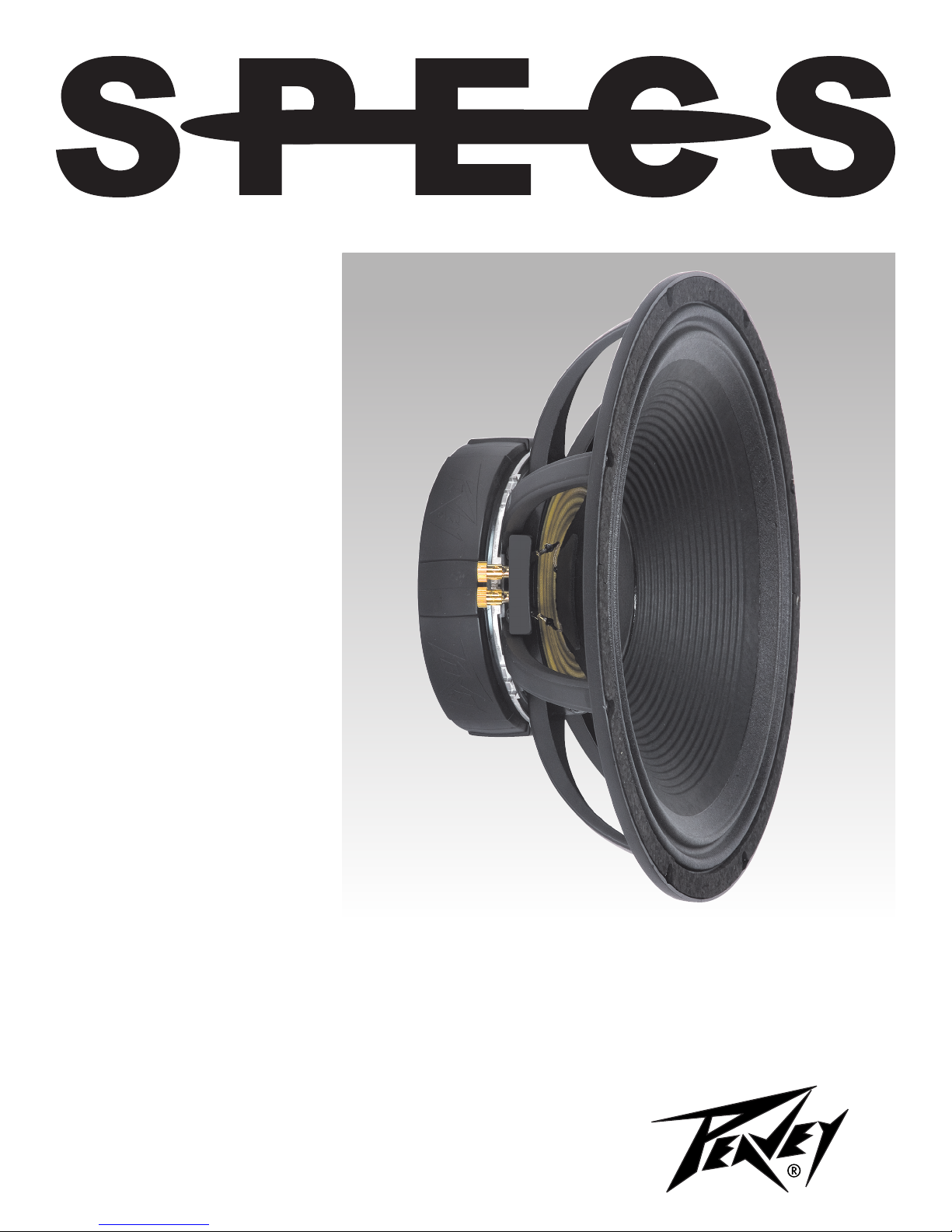
Peavey Lo Max® 18
00560400
Peavey Lo Max® 15
00560290
Finally, there’s a subwoofer
driver that just might be stronger
than your biggest amplier. With
an almost inconceivable power
handling capacity of 2400 watts
program, the Lo Max has more
real world power handling than any
other commercially available sound
reinforcement loudspeaker. A no
compromise design combines this
power capacity with high efciency,
excellent frequency response and
low distortion for revolutionary
performance. It even works well in
compact enclosures.
DESIGN
The Lo Max utilizes the same strong
Kevlar® composite cone and dustcap
used in the Low Rider® series.
The cone is strong and tough, and
uses an innovative asymmetrical-M
surround for superior excursion and
motion control.
High quality gold on brass spring
plunger terminals accepting large
gauge wire are attached to large
diameter, high-current tinsel leads
with silver solder to withstand high
currents, high temperatures and long
excursion. The tinsel termination is
coated with an elastomer material to
improve ex life.
The massive 4” diameter voice coil
uses polyamide insulated copper
ribbon wire, edge wound and
bonded onto an incredibly durable
and heat resistant polyamide
composite former. With a winding
length of 1.150”, the long coil
has much more surface area to
dissipate heat, and its increased
length drives the cone to a far
higher excursion. The coil is over
coated with a tough thermoset
epoxy for added durability,
abrasion resistance and heat
dissipation.
The coil wires are solderless
diffusion welded to high
conductivity OFHC copper ribbon
Page 2

leads, which are embedded
inside the former assembly
and soldered to the tinsel leads
with high temperature silver
solder. The solder joint is then
coated with a special, thermally
conductive silicone adhesive
for encapsulation and heat
dissipation.
The voice coil assembly is bonded
to the Kevlar® composite cone and
new, incredible tough plastiseal
coated Nomex® progressive
roll spider using a thermoset
epoxy originally developed for
attaching nose cones onto ICBM
missiles — truly an aerospace
grade adhesive. The spider and
surround are bonded to the frame
with a high strength, toughened
adhesive.
The stunning, 28lb., chrome-
plated Lo Max magnet structure is
all new and was designed using
extensive Finite Element computer
modeling. The back plate/pole
piece is cold forged from a single
massive billet of ultra low carbon
steel and is a prime example of
form following function. The pole
is extended well beyond the 12.5
mm thick front plate to improve
coil cooling and make it more
magnetically linear. The magnet
structure is powered by two full
size Black Widow® magnets in
stacked conguration.
A specially designed vent plate
greatly improves voice coil
cooling. This heat conductive,
ported and nned aluminum, ring
delivers cool air pumped by the
spider directly to the voice coil
to keep operating temperatures
under control. The improved
cooling increases power handling
and reliability and reduce power
compression.
The cast aluminum frame is tough
and rigid and has the strength
needed to hold the cone and
huge magnet assembly in perfect
alignment. The deep dish design
and large spider clearance make
high excursion and high output
possible.
These dynamic new drivers
also utilize the user friendly
Black Widow replaceable basket
assemblies with Rubatex® gaskets.
The results of these specially
designed components are truly
amazing loudspeakers. The
extremely high power handling and
more than 1.5” of available cone
travel combine for astonishing
low frequency output, while the
possibility of small enclosures
adds a new dimension to compact,
high output sound reinforcement
systems.
APPLICATIONS
The Lo Max is specically
designed for subwoofer use, with
extremely high output capabilities
and almost inconceivable power
handling. While most subwoofer
applications are below 150 Hz, it
is usable to frequencies as high
as 500 Hz.
The compact enclosure
designs are ideal for instrument
amplication and high portability
applications such as DJ and small
touring bands. They provide solid
bass performance in extraordinarily
small enclosures. The very small
size offers interesting possibilities
to large touring systems due to
reduced load out volume.
The medium sized enclosures
are smaller than usual and have
more bass extension and much
higher output capabilities than
conventional designs. They
are excellent choices for thigh
performance sound reinforcement.
For permanent installations and
applications requiring extremely
deep bass performance, the large
vented enclosures are ideal. The
extreme, deep bass and high
sound pressure levels these
systems can produce are almost
beyond comprehension.
Due to the Lo Max’s high output
capabilities, excessive levels
may cause structural damage to
buildings or induce permanent
hearing loss, nausea, vertigo or
intestinal disturbances in listeners.
Please be cautious when setting
maximum sound pressure levels.
ENCLOSURES
To assist with the growing interest
in home built enclosure designs,
Peavey provides complete
parameter data on these drivers,
as well as several recommended
enclosures for each model. This
information and much more can be
found at www.peavey.com
Lo Max drivers are intended for
use in vented enclosures only.
Other enclosure designs such as
sealed, horn-loaded, bandpass and
innite bafe will result in reduced
performance and/or possible driver
overheating and failure.
Since vented enclosures
allow driver over-excursion at
frequencies below vent tuning,
active ltering absolutely must be
included with ampliers greater
than 750 watts. This lter should
be a high pass 24 dB Butterworth
at a minimum of 32 Hz for the 15”.
Filtering is also recommended
below 750 watts in order to
conserve amplier power. Failure
to use high pass ltering with
high power operation may cause
driver damage that could void your
warranty.
Enclosures should be built of
best quality ¾” to 1-1/4” (20mm
to 32mm) marine, 7-ply birch or
other high grade plywood. Use
of construction grade plywood is
Page 3

strongly discouraged, but if no
better material is available choose
grade BC or better and don’t use
wood with loose plies or voids.
Use quality wood glue and t
joints tightly. Dado corner joints
are highly recommended. Wood
screws or a pneumatic nailer
should be used to assemble
the enclosure during gluing to
maximize joint strength.
The strength of the completed
enclosure has a great effect on
the bass performance of the
nished system. Internal bracing
will be required to improve the
structural stiffness of the cabinet
the Lo Max drivers will generate
enormous forces inside the
enclosure, and panels that aren’t
stiff enough will vibrate and cancel
bass output while producing
undesirable resonances.
Vents shown in the examples
require standard schedule 40 PVC
pipe for vent construction. The
pipe should be dadoed tightly into
the back of the bafe and glued
rmly in place with high quality
epoxy or high strength industrial
grade hot glue. Rough up the
outside of the pipe to improve the
glue bond. Radius the inside of the
vent ends to improve air ow and
reduce vent noise.
Lo Max drivers generate huge
amounts of heat at high power.
This heat is transferred to the air
in the enclosure as it is dissipated.
For long term (i.e., greater than
15 minutes) high power operation,
this heated air must escape and be
replaced by cooler air. Enclosure
vents should be placed at the top
and bottom vents. Enclosures
not designed in this way will be
thermally de-rated, and will not be
capable of sustained operation at
high power due to heat build- up.
Vents for these enclosures are
much longer than typical for a
sound reinforcement subwoofer.
This reects the special
characteristics of the Lo Max’s
design that make it possible to
combine a large, high excursion
woofer with an unusually small
enclosure. For best performance,
the inside ends of the vents should
be a distance of at least one vent
diameter from any interior wall of
the enclosure. The vent should
be straight, without elbow ttings
or other methods to bend it for
greater length. Vent diameter
should not be decreased, as high
air velocity will result in noise and
reduced power handling.
Be sure to allow for the
displacement of the vent, bracing
and woofer in your enclosure
design before building it. Mistakes
in net volume will mistune the
enclosure and can drastically
reduce performance. This will
require considerable planning
before construction, but is well
worth the extra effort.
Line the inside of the enclosure with
polyester ber batting such as quilt
stufng. The batting material should
conform to California bedding
re codes. Attach the batting with
spray adhesive or staples and keep
material away from the end of the
vent tube where it can be pulled in
by air ow.
Handles, protective corners,
cabinet covering, grille materials
and crossovers are available
through Peavey Accessories. Take
particular care when positioning
the handles, as subwoofers tend to
be large and heavy.
Do not use ¼” phone plugs or
jacks in the construction of your
enclosure. The power capacity
of Lo Max drivers is well above
safe limits for phone plugs
and jacks, and their use may
constitute a re hazard. Neutrik®
Speakon® connectors are highly
recommended, and internal
cabinet wiring should be at least
16-gauge stranded copper wire.
These instructions are a general
guideline for design. Proper
construction techniques, good
planning and common sense will
result in a reliable, high quality,
performance system.
Peavey in no way accepts liability
for any damage, accident or
injury that may result from design,
construction or operation of
enclosures using this information.
PARAMETERS
Thiele-Small parameters for Lo
Max subwoofers follow. This data
is for use in designing enclosures.
Numerous software packages
are available that use this data
to simulate the response of the
driver and enclosure together
for optimum performance in any
application.
Page 4

Kapton® is a registered trademark of DuPont.
Kevlar® is a registered trademark of DuPont.
Nomex® is a registered trademark of DuPont.
Rubatex® is a registered trademark of Rubatex Corporation.
PARAMETER DEFINITIONS
Znom: The nominal impedance of the driver in
Ohms.
Revc: DC resistance of the driver in ohms, also
known as Re.
Sd: The functional radiating surface area of the
cone assembly in meters 2.
BL: Efciency of the voice coil and magnet
system in Tesla meters.
Fo: Free air resonance. Also known as Fs.
Vas: Volume of air having the same compliance
(springiness) as the driver’s suspension.
Cms: Restorative force of the driver’s
suspension in micrometers/Newton.
Mms: The total mass of the moving parts of the
loudspeaker, including the air load, in grams.
Qms: Resonance characteristics of the
mechanical factors of the loudspeaker.
Qes: Resonance characteristics of electrical
factors of the loudspeaker.
Qts: Resonance characteristics of the electrical
and mechanical factors combined together.
Xmax: Distance the cone can move in one
direction before the coil begins to leave the
magnetic gap.
Le: Inductance of the voice coil in millihenries.
SPL: Typical sound pressure level at 1 watt, 1
meter.
no: Electrical to acoustical conversion efciency
in percent.
Vd: Air displacement of the driver from negative
Xmax to positive Xmax.
Pmax: Maximum continuous program power in
watts.
Disp: Volume displaced by the driver inside the
cabinet when mounted on its rear ange
Page 5

SPECIFICATIONS Lo Max® 18” Lo Max® 15”
Part # 00560400 00560290
Size: inches / mm 18 / 460 nominal 15/ 380 nominal
Frame OD: inches / mm 18-1/8 / 460 15-1/4 / 387
Bolt circle: inches / mm 17-3/8 / 441 14-9/16 / 370
Cutout diameter: inches / mm 16-3/4 / 425 14-1/8 / 359
Depth: inches / mm 8-1/8 / 200 7-1/2 / 190.5
Impedance: 8 Ohms 8 Ohms
Power Capacity: 4800 Watts peak 4800 Watts peak
2400 Watts program 2400 Watts program
1200 Watts continuous 1200 Watts continuous
40 Hz - 400 Hz 40 Hz - 400 Hz
Sensitivity: 97.1 dB / 1 W 1m 95.1 dB / 1 W 1 m
Usable frequency range: 30 Hz -500 Hz 30 Hz -500 Hz
Cone: Kevlar® impregnated cellulose Kevlar impregnated cellulose
Voice coil diameter: 4.0”/100 mm 4.0”/100 mm
Voice coil material: Polyimide coated copper ribbon wire Polyimide coated copper ribbon wire
Polyimide – impregnated Polyimide – impregnated
berglass former berglass former
Nomex® stiffener Nomex stiffener
Solderless diffusion welded Solderless diffusion welded
OFHC Copper Leads OFHC Copper Leads
Net weight: lb./kg 33.5 / 15.2 kg 32.5 / 14.8 kg
Znom (ohms) 8 8
Revc (ohms) 5.40 5.40
Sd (Square Meters) 0.118 0.089
BL (T/M) 23.40 23.40
Fo (Hz) 31.5 38.5
Vas (liters) 294.4 124.0
Cms (uM/N) 140.0 110.8
Mms (gm) 194.68 146.00
Qms 11.15 11.00
Qes 0.330 0.364
Qts 0.386 0.385
Xmax (mm) 10.2 10.2
Le (mH) 0.75 0.75
SPL (1 W 1m) 95.5 95.5
no (%) 2.20 2.20
Vd (cubic inches/milliliters) 73.06 / 1197 55.15 / 904
Pmax (Watts pgm.) 2400 2400
Disp (inches3 / milliliters) 310 / 5080 242 / 3960
Page 6

SUGGESTED ENCLOSURES
For those who want to build their own enclosures but don’t want to go through the design process using driver
parameters, Peavey provides the following optimized designs:
For Lo Max 18:
ENCLOSURE NET VOLUME
Cubic feet/liters (qty) inches/mm inches/mm frequency in Hz point in Hz
Small Vented Box 4.0 /113.3 (4) 4” / 102 12.5 / 318 44 44
Medium Vented Box 6.0 / 170.0 (4) 4” / 102 10 / 254 39 37
Large Vented Box 8.0 / 226.6 (4) 4” / 102 10.625 / 270 33 31
VENT DIAMETER VENT LENGTH Vb BOX TUNING F3, -3 Db
1. Small Vented Box
This enclosure is as small as many 15” cabinets but has better bass performance and handles tons
of power. This design is an excellent choice for large touring systems because it can handle a large
number of enclosures at the same load-out volume.
2. Medium Vented Box
This enclosure offers an exceptional combination of deep bass extension, high power handling and
reasonable size. It is capable of extremely high output (below 35Hz) for excellent performance
3. Large Vented Box
The large vented box produces skull crushing levels of extremely deep bass and is usable to 24Hz
(-10 dB limit) at sound reinforcement SPL levels. As is typical with large vented enclosures, power
handling is reduced about 20%.
For Lo Max15:
ENCLOSURE NET VOLUME
Cubic feet/liters (qty) inches/mm inches/mm frequency in Hz point in Hz
Small Vented Box 2.0 /56.6 (4) 2” / 51 7.5 / 191 41 50
Medium Vented Box 3.0 / 85 (4) 3” / 76 12 / 305 40 38
Large Vented Box 4.0 / 113.3 (4) 3” / 76 9 / 229 39 34
VENT DIAMETER VENT LENGTH Vb BOX TUNING F3, -3 Db
1. Small Vented Box
This incredibly tiny enclosure had good bass performance and serious power capacity. An excellent
choice for very compact, high powered systems and bass guitar/keyboard enclosures.
2. Medium Vented Box
This enclosure is an exceptional compromise of deep bass extension, high power handling, and
compact size. Remarkable bass extension and power handling.
3. Large Vented Box
This large vented box generates incredibly powerful deep bass and is usable to 28 Hz (-10 dB limit)
at sound reinforcement SPL levels. As is typical with large vented enclosures, power handling is
reduced about 20%.
Page 7

Peavey
Lo Max®
speakers
feature convenient
eld-replaceable
1
2
baskets. Replaceable
baskets eliminate the
need for re-coning
speakers and the
frustration and delays
associated with the
re-coning process. It
only takes a few minutes
to replace a basket
and you are back in
business. It just can’t get
any easier than the four
steps outlined here.
3
Baskets are replaced in four easy steps:
1 Remove three screws on back of magnet structure.
2 Lift the magnet structure off the basket frame.
3 Clean the voice coil “gap”.
4 Align screw holes, lower structure into place on new
basket frame, insert screws and tighten.
4
NOTE: For details, refer to the warranty statement. Copies of this statement may be obtained online at www.peavey.com.
ONE YEAR LIMITED WARRANTY
Page 8

Features and specications are subject to change without notice.
Logo referenced in Directive 2002/96/EC Annex IV
(OJ(L)37/38,13.02.03 and defined in EN 50419: 2005
The bar is the symbol for marking of new waste and
is applied only to equipment manufactured after
13 August 2005
Peavey Electronics Corporation • 5022 Hartley Peavey Drive • Meridian • MS • 39305
(601) 483-5365 • FAX (601) 486-1278 • www.peavey.com
©2011 Printed in the U.S.A. 1/11 80306034
 Loading...