

Page 1
ICA
™
SERIES
INDUSTRIAL CONTRACTOR AMPLIFIERS
OPERATING GUIDE
Page 2
2
Intended to alert the user to the presence of uninsulated “dangerous voltage” within the product’s
enclosure that may be of sufficient magnitude to constitute a risk of electric shock to persons.
Intended to alert the user of the presence of important operating and maintenance (servicing)
instructions in the literature accompanying the product.
CAUTION: Risk of electrical shock — DO NOT OPEN!
CAUTION: To reduce the risk of electric shock, do not remove cover. No user serviceable parts inside. Refer
servicing to qualified service personnel.
WARNING: To prevent electrical shock or fire hazard, do not expose this appliance to rain or moisture. Before
using this appliance, read the operating guide for further warnings.
Este símbolo tiene el propósito, de alertar al usuario de la presencia de “(voltaje) peligroso” sin aislamiento dentro de la caja del producto y que puede tener una magnitud suficiente como para constituir
riesgo de descarga eléctrica.
Este símbolo tiene el propósito de alertar al usario de la presencia de instruccones importantes sobre la
operación y mantenimiento en la información que viene con el producto.
PRECAUCION: Riesgo de descarga eléctrica ¡NO ABRIR!
PRECAUCION: Para disminuír el riesgo de descarga eléctrica, no abra la cubierta. No hay piezas útiles dentro.
Deje todo mantenimiento en manos del personal técnico cualificado.
ADVERTENCIA: Para evitar descargas eléctricas o peligro de incendio, no deje expuesto a la lluvia o humedad
este aparato Antes de usar este aparato, Iea más advertencias en la guía de operación.
Ce symbole est utilisé dans ce manuel pour indiquer à l’utilisateur la présence d’une tension dangereuse
pouvant être d’amplitude suffisante pour constituer un risque de choc électrique.
Ce symbole est utilisé dans ce manuel pour indiquer à l’utilisateur qu’il ou qu’elle trouvera d’importantes
instructions concernant l’utilisation et l’entretien de l’appareil dans le paragraphe signalé.
ATTENTION: Risques de choc électrique — NE PAS OUVRIR!
ATTENTION: Afin de réduire le risque de choc électrique, ne pas enlever le couvercle. Il ne se trouve à l’intérieur
aucune pièce pouvant être reparée par l’utilisateur. Confiez I’entretien et la réparation de l’appareil à un réparateur
Peavey agréé.
AVERTISSEMENT: Afin de prévenir les risques de décharge électrique ou de feu, n’exposez pas cet appareil à la
pluie ou à l’humidité. Avant d’utiliser cet appareil, lisez attentivement les avertissements supplémentaires de ce
manuel.
Dieses Symbol soll den Anwender vor unisolierten gefährlichen Spannungen innerhalb des Gehäuses
warnen, die von Ausreichender Stärke sind, um einen elektrischen Schlag verursachen zu können.
Dieses Symbol soll den Benutzer auf wichtige Instruktionen in der Bedienungsanleitung aufmerksam
machen, die Handhabung und Wartung des Produkts betreffen.
VORSICHT: Risiko — Elektrischer Schlag! Nicht öffnen!
VORSICHT: Um das Risiko eines elektrischen Schlages zu vermeiden, nicht die Abdeckung enfernen. Es befinden
sich keine Teile darin, die vom Anwender repariert werden könnten. Reparaturen nur von qualifiziertem
Fachpersonal durchführen lassen.
ACHTUNG: Um einen elektrischen Schlag oder Feuergefahr zu vermeiden, sollte dieses Gerät nicht dem Regen
oder Feuchtigkeit ausgesetzt werden. Vor Inbetriebnahme unbedingt die Bedienungsanleitung lesen.
Page 3

TABLE OF CONTENTS
Page
INTRODUCTION . . . . . . . . . . . . . . . . . . . . . . . . . . . . . . . . . . . . . . . . . . . . . . . . . . . . 4
UNPACKING . . . . . . . . . . . . . . . . . . . . . . . . . . . . . . . . . . . . . . . . . . . . . . . . . . . . . . . 4
INSTALLATION AND MOUNTING . . . . . . . . . . . . . . . . . . . . . . . . . . . . . . . . . . . . . . . 4
BASIC SETUP. . . . . . . . . . . . . . . . . . . . . . . . . . . . . . . . . . . . . . . . . . . . . . . . . . . . . . 4
FRONT PANEL FEATURES. . . . . . . . . . . . . . . . . . . . . . . . . . . . . . . . . . . . . . . . . . . . 5
BACK PANEL FEATURES . . . . . . . . . . . . . . . . . . . . . . . . . . . . . . . . . . . . . . . . . . . . . 6
OPERATION . . . . . . . . . . . . . . . . . . . . . . . . . . . . . . . . . . . . . . . . . . . . . . . . . . . . . . . 7
PROTECTION FEATURES . . . . . . . . . . . . . . . . . . . . . . . . . . . . . . . . . . . . . . . . . . . . 9
SEQUENTIAL TURN-ON / TURN-OFF. . . . . . . . . . . . . . . . . . . . . . . . . . . . . . . . . . . . 10
WIRE GAUGE CHART . . . . . . . . . . . . . . . . . . . . . . . . . . . . . . . . . . . . . . . . . . . . . . . 11
ICA
™
600 SPECIFICATIONS . . . . . . . . . . . . . . . . . . . . . . . . . . . . . . . . . . . . . . . . . . . 12
ICA
™
1200 SPECIFICATIONS . . . . . . . . . . . . . . . . . . . . . . . . . . . . . . . . . . . . . . . . . . 13
ICA™2400 SPECIFICATIONS . . . . . . . . . . . . . . . . . . . . . . . . . . . . . . . . . . . . . . . . . . 14
ICA
™
400V SPECIFICATIONS . . . . . . . . . . . . . . . . . . . . . . . . . . . . . . . . . . . . . . . . . . 15
ICA™800V SPECIFICATIONS . . . . . . . . . . . . . . . . . . . . . . . . . . . . . . . . . . . . . . . . . . 16
ICA
™
2400V SPECIFICATIONS . . . . . . . . . . . . . . . . . . . . . . . . . . . . . . . . . . . . . . . . . 17
IMPORTANT SAFETY INSTRUCTIONS. . . . . . . . . . . . . . . . . . . . . . . . . . . . . . . . . . . 18
WARRANTY INFORMATION . . . . . . . . . . . . . . . . . . . . . . . . . . . . . . . . . . . . . . . . . . . 19
3
Page 4

INTRODUCTION
Congratulations on your purchase of an Architectural Acoustics ICA
™
(Industrial Contractor Amplifier)
from Peavey Electronics. Please read this manual carefully, especially the IMPORTANT SAFETY
INSTRUCTIONS on page 18. It contains information vital to safe operation of the power amplifier.
Also, please fill out and return the enclosed product registration card.
ICA Series amplifiers represent new levels of value and flexibility never before offered to the
contracting market. The ICA Series features models specifically designed to drive 4-ohm outputs,
70.7-volt outputs, and 100-volt outputs. 70.7 and 100-volt outputs can be driven directly, eliminating
the need for transformers or autoformers. These amplifiers cover almost every installed or
distributed sound power requirement imaginable.
ICA Series amplifiers are ruggedly built from high-quality components and feature comprehensive
protection circuits to protect your amplifier from those “real world” occurrences.
If you need setup or operational assistance for this product, please call the Peavey Electronics
Customer Service Department or your local Peavey Electronics representative. We appreciate
suggestions that may help us improve our products and/or service.
UNPACKING
Inspect the amplifier during unpacking. If you find any damage, notify your dealer immediately.
Only the consignee may institute a claim with the carrier for damage incurred during shipping. Be
sure to save the carton and all packing materials. Should you ever need to ship the unit back to
Peavey Electronics, one of its service centers, or the dealer; use only the original factory packing.
INSTALLATION AND MOUNTING
ICA Series amplifiers are 2 or 3-rack-space units of 15 3/4" (400 mm) depth that mount in a
standard 19" rack. On all amplifiers, front panel mounting holes are provided.
BASIC SETUP
1. Rack mount the amplifier in the location where it is to be used, remembering to allow for
adequate access and cooling space. For more information, see the sections on
INSTALLATION AND MOUNTING and COOLING REQUIREMENTS.
2. Make input connections to the plugable terminal blocks on the rear panel. Use the proper
connections for stereo, parallel, bridged mono, and grounding configuration. See the sections
on SIGNAL MODE CONFIGURATION and INPUT MODULE CONNECTIONS for more
information.
3. Connect speakers to the output barrier strip. Be sure to make the correct output connections
for stereo, parallel or bridged mono configuration. See the section on SPEAKER OUTPUT
CONNECTIONS for more information.
4. Make power connections, allowing for proper current draw. See the sections on IEC POWER
CONNECTOR and AC MAINS CIRCUIT SIZE REQUIREMENTS for more information.
5. Turn the front panel 3-position AC POWER switch to ON and bring up the back panel LEVEL
(gain) attenuators to the desired levels.
4
ENGLISH
Page 5

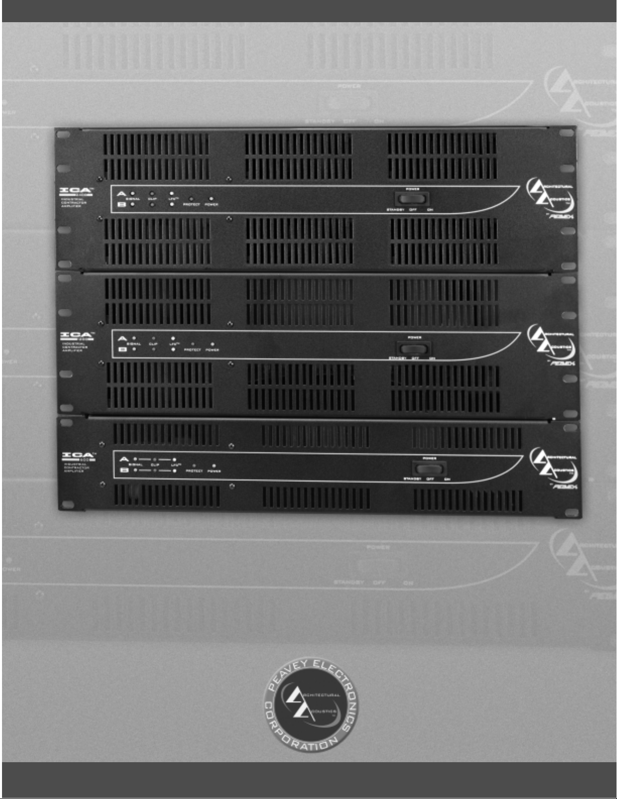
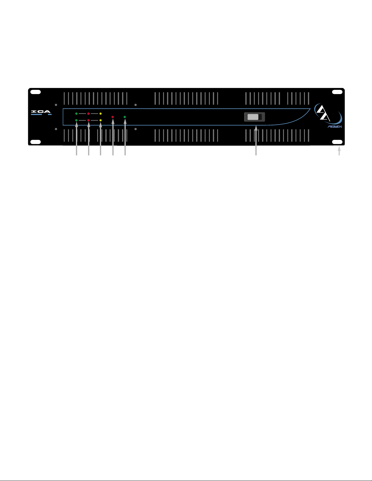
FRONT PANEL FEATURES
1. RACK MOUNTING EARS
These mounting holes are provided on each front mounting ear.
2. 3-POSITION AC POWER SWITCH
A 3-position switch is on the front panel. Sequential remote turn-on capability is a standard
feature. With the switch pushed towards the outside position, the amplifier is ON. The middle
position is OFF, and the inside position is marked STANDBY. When switched to STANDBY,
the amplifier may be activated by the sequential turn-on circuit. See the section on
SEQUENTIAL TURN-ON / TURN-OFF for more information.
3. POWER LED
The POWER LED illuminates when the amplifier is turned on.
4. SIGNAL LED
Each channel has a SIGNAL LED that illuminates when the amplifier output exceeds 1 volt.
5. CLIP LED
Each channel has a CLIP LED that illuminates at the clipping point, and indicates that internal
circuitry is reducing amplifier gain to allow full power. See the section on PROTECTION
FEATURES for more information.
6. LFC
™
LED
Each channel has a LFC (Load Fault Correction) LED. This LED illuminates when the
amplifier channel detects an abnormal load condition. Internal circuitry will instantaneously
reduce the channel gain to allow the amplifier to operate at a safe level into the abnormal
load. See the section on PROTECTION FEATURES for more information.
7. PROTECT LED
If the amplifier has just been turned on or has detected a fault condition, the speaker output
relays will open, illuminating this LED.
5
4
5
6 7 3
2
1
TM
600
INDUSTRIAL
CONTRACTOR
AMPLIFIER
A
B
LFCCLIPSIGNAL
TM
PROTECT
POWER
STANDBY
POWER
OFF ON
RCHITECTURAL
COUSTICS
by
TM
Page 6
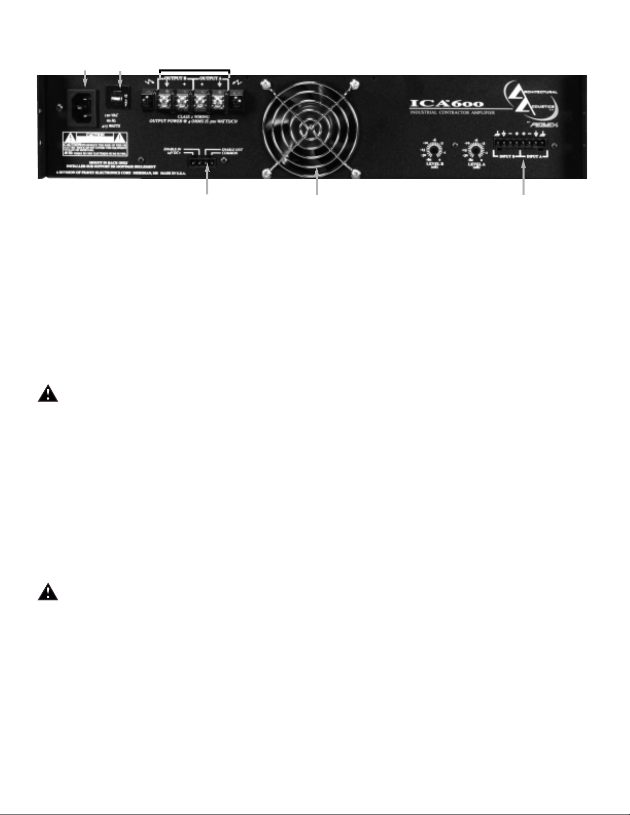
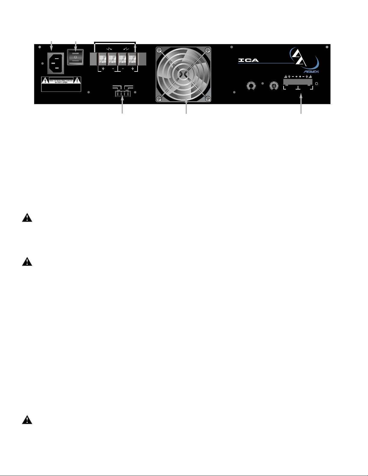
BACK PANEL FEATURES
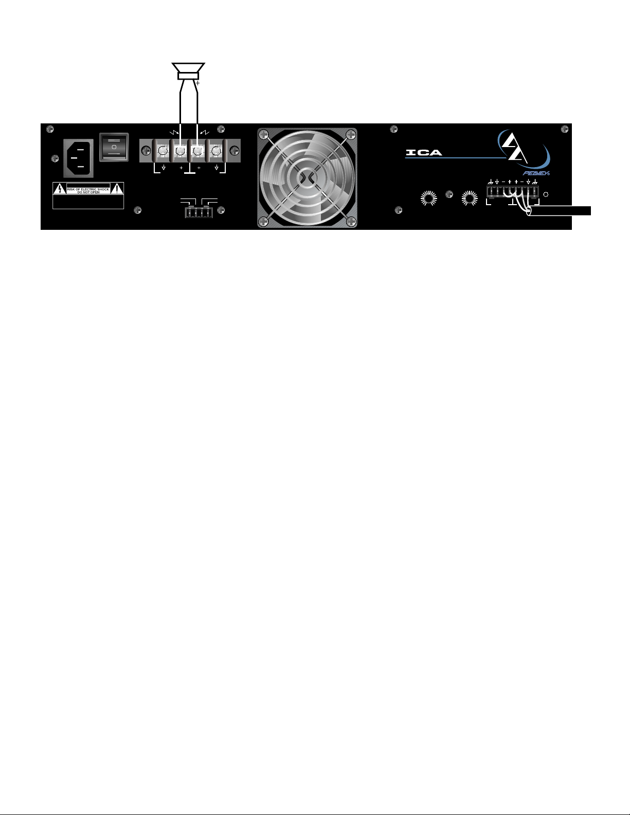
8. INPUT SECTION
The ICA
™
Series comes standard with plugable input connectors and individual channel rotary
attenuators. Connections at the input connector permit the audio signal ground to be
connected or lifted from the chassis ground.
9. OUTPUT BARRIER STRIP
A barrier strip is provided for connection of loudspeakers with bare wire or spade lug
connectors. This barrier strip can accommodate up to two 10-gauge wires per terminal.
10. IEC POWER CONNECTOR
A standard IEC power connector is located at the upper left corner of the amplifier rear panel.
An AC mains cord having an appropriate AC plug for the intended operating voltage is
included.
NOTE: FOR UK ONLY
If the colors of the wires in the mains lead of this unit do not correspond with the colored
markings identifying the terminals in your plug, proceed as follows: (1) The wire that is
colored green and yellow must be connected to the terminal that is marked by the letter E,
the earth symbol, colored green, or colored green and yellow. (2) The wire that is colored
blue must be connected to the terminal that is marked with the letter N or the color black. (3).
The wire that is colored brown must be connected to the terminal that is marked with the
letter L or the color red.
11. CIRCUIT BREAKER
A resettable, protective AC circuit breaker is located at the upper left of the amplifier back
panel. If the breaker has tripped, push it back in to return the amplifier to operating condition.
If the breaker continues to trip, the amplifier needs servicing. Do not continue to reset the
breaker because severe internal damage and safety hazards could occur!
12. SEQUENTIAL TURN-ON CONNECTOR
The ICA
™
Series comes standard with remote-controllable sequential turn on enabled by
setting the front power switch to STANDBY. The amplifier is activated by applying a voltage
between 12 to 24 volts DC to the rear-mounted, 4-pin plugable terminal, and connecting the
ENABLE terminal to the 24 V DC+ terminal. When no voltage is present or the ENABLE
connection is opened, the amplifier will switch off. Other ICA Series amplifiers can be “daisy
chained” by connecting all 24 V DC+ terminals together, all COMMON terminals together, and
6
1110
9
12
13 8
Page 7

connecting the ENABLE OUT to the ENABLE IN of the next amplifier. A mating connector is
shipped with the amplifier.
13. FAN GRILL
A continuously variable-speed DC fan supplies cool air into the amplifier. Do not block this
intake! The fan operates only when the amplifier heat sinks require cooling.
OPERATION
AC MAINS CIRCUIT SIZE REQUIREMENTS
Power requirements for ICA™amplifiers are rated at “idle”, 1/8 power (“typical” music
conditions), 1/3 power, and maximum rated power. The maximum power current draw rating
is limited by the amplifier’s circuit breaker. Consult the specification sheet for the current that each
amplifier will demand. AC mains voltage must be the same as that indicated on the back of the
amplifier. Damage caused by connecting the amplifier to improper AC voltage is not covered by any
warranty. NOTE: Always turn off and disconnect the amplifier from the mains voltage before making
audio connections. As an extra precaution, have the input attenuators turned down during initial
power up.
COOLING REQUIREMENTS
ICA Series amplifiers use a forced-air cooling system to maintain a low, even operating
temperature. Cooling air is drawn by a continuously variable-speed fan mounted on the back
panel, and exhausts through slots on the front panel. The fan will remain inactive until internal
operating temperature rises above 45º C (113º F). Make sure there is enough space around the
back of the amplifier to allow air to enter. NOTE: If the amplifier is rack mounted, do not use doors
or covers on the front or back without pressurizing the back of the rack. Whatever type of rack you
are using, make sure that heated air can escape freely, and that there is no resistance to the intake
of cool air through the back grill. Intake and exhaust air must flow without resistance.
HIBERNATION
™
All ICA Series amps feature Hibernation circuitry. Current draw and thermal emissions are at a
minimum when the absence of input signal is sensed for more than a minute. Once signal is
present, Hibernation instantly restores the amplifier to normal. Current draw specifications while
Hibernation is active are included in specifications under Idle Current Draw.
THERMAL EMISSIONS
The system installer or designer should specify system cooling needs. Refer to the specifications at
the back of this manual for specific thermal emissions figures.
INPUT CONNECTIONS
The input connector accepts balanced and unbalanced audio signals. For use with an unbalanced
source, tie the inverting (-) input to ground by installing a jumper to the signal ground connection. If
the inverting input is left floating, a 6 dB loss in gain will result.
7
Page 8
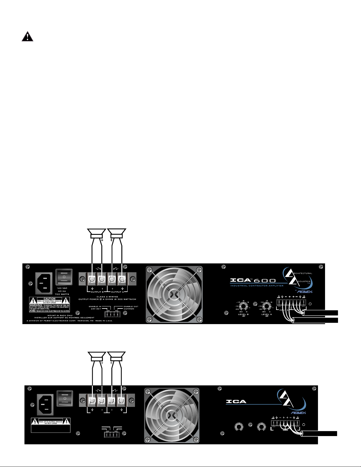
SIGNAL MODE CONFIGURATION
ICA
™
Series amplifiers are configured for Stereo (2-channel), Bridged Mode, or Parallel Mode
operation at the input connector.
To send the same signal to both channels (Parallel Mode), connect the input signal to CHANNEL A
via the input connector. Run jumpers from the positive and negative terminals of the CHANNEL A
input connector to the respective terminals of CHANNEL B. Both channels then share the
CHANNEL A input signal but will operate independently. Speakers are connected as in Stereo Mode.
Bridged Mode converts the amplifier into a single-channel unit with a power rating equal to the sum
of both channel power ratings, and at a load rating twice that of the single-channel rating. In Bridged
Mode, the channels operate at opposite polarity of each other so that one channel “pushes” and the
other “pulls” equally. Signal is connected to the input connector with one jumper connecting the
positive (+) terminal of Input A to the negative (-) terminal of Input B, and another jumper connecting
the negative (-) terminal of Input A to the positive (+) terminal of Input B. Both channel attenuators
(A & B) are used to control signal level, and both must be at the same level, preferably at 0 dB
attenuation. The speakers are connected only to the designated “+” output terminals. NEVER
ground either side of the speaker cable when the amplifier is in Bridged Mode as both sides
are “hot”. If an output patch panel is used, all connections must be isolated from each other and
from the panel. For ICA Series amplifiers, the minimum nominal load impedance in Bridged Mode is
8 ohms; this is the equivalent of driving both channels at 4 ohms. Driving loads of less than 8 ohms
may activate the LFC circuit and may also cause a thermal protect condition. NOTE: Regardless of
operating mode, NEVER connect amplifier outputs together!
STEREO MODE CONNECTION DIAGRAM
PARALLEL MODE DIAGRAM
8
120 VAC
60 Hz
700 WATTS
CAUTION
TO REDUCE THE RISK OF FIRE OR
WARNING:
ELECTRIC SHOCK DO NOT EXPOSE THIS EQUIPMENT
TO RAIN OR MOISTURE.
RISQUE DE CHOC ELECTRIQUE-NE PAS OUVRIR.
AVIS:
MOUNT IN RACK ONLY
INSTALLER SUR SUPPORT DE MONTAGE SEULEMENT
A DIVISION OF PEAVEY ELECTRONICS CORP. MERIDIAN, MS MADE IN U.S.A.
OUTPUT B OUTPUT A
CLASS 2 WIRING
OUTPUT POWER @ 4 OHMS IS 300 WATTS/CH
ENABLE IN
24V DC+
ENABLE OUT
COMMON
TM
-6
-3
-10
-15
-1
-30
-80
0
LEVEL B
(dB) (dB)
600
-10
-15
-30
LEVEL A
-6
-3
-1
0
-80
INDUSTRIAL CONTRACTOR AMPLIFIER
INPUT B
RCHITECTURAL
COUSTICS
by
INPUT A
TM
Page 9
BRIDGED MODE DIAGRAM
SPEAKER OUTPUT CONNECTIONS
Speakers are connected using the output barrier strip connectors. Spade lugs, ring tongues or bare
wire may be connected to the output barrier strip elements. The barrier strip can accommodate up to
two 10-guage wires per terminal. Make sure the amplifier is turned off before you change any output
connections or jumpers. Consult the Wire Gauge Chart at the back of this manual to find a suitable
wire gauge to minimize losses of power in the speaker cables. Also, make sure that the load
impedance is not lower than that rated for the amplifier.
SIGNAL GROUND CONNECTION
Connections at the input connector permit the audio signal ground to be connected or lifted from the
chassis ground. When possible, the shield of the signal source connecting cable should connect to
the chassis ground. In some cases, however, particularly if an amplifier is being installed in an
existing system, this may result in a ground loop. If this happens, connect the shield to the signal
ground only. The chassis ground also connects to the AC ground internally. If the cable shield is
connected to the signal ground only, it will be clamped to +/- 0.6 V above or below chassis/AC
ground.
PROTECTION FEATURES
The ICA™Series incorporates protection features derived from Peavey’s extensive experience with
reliability. The amplifiers are ruggedly built from high-quality components and feature comprehensive
protection circuits to protect your amplifier from those “real world” occurrences.
CLIP LIMITING
At the amplifier’s full power, or clipping point, the channel gain will automatically be reduced,
guarding the loudspeakers against damaging high power and continuous square waves that would
otherwise be produced. This is indicated by illumination of the CLIP LED. Normal program transients
will not trigger Clip Limiting, only steady or excessive clipping will. Operation is virtually transparent
in use and full signal bandwidth is maintained.
LOAD FAULT CORRECTION
™
LFC is an innovative circuit that will instantaneously reduce channel gain to allow the amplifier to
operate at a safe level into an abnormal load. LFC activation is indicated by illumination of the LFC
LED. Moderate activation of LFC is inaudible in normal use. In addition, if extreme low impedance or
a short circuit is encountered during high signal level conditions, the amplifier’s output relay will
open.
9
INPUT B
RCHITECTURAL
COUSTICS
TM
by
INPUT A
120 VAC
60 Hz
700 WATTS
CAUTION
TO REDUCE THE RISK OF FIRE OR
WARNING:
ELECTRIC SHOCK DO NOT EXPOSE THIS EQUIPMENT
TO RAIN OR MOISTURE.
RISQUE DE CHOC ELECTRIQUE-NE PAS OUVRIR.
AVIS:
A DIVISION OF PEAVEY ELECTRONICS CORP. MERIDIAN, MS MADE IN U.S.A.
MOUNT IN RACK ONLY
INSTALLER SUR SUPPORT DE MONTAGE SEULEMENT
OUTPUT B OUTPUT A
OUTPUT POWER @ 4 OHMS IS 300 WATTS/CH
CLASS 2 WIRING
ENABLE IN
24V DC+
ENABLE OUT
COMMON
TM
INDUSTRIAL CONTRACTOR AMPLIFIER
-15
-30
600
-6
-3
-10
-1
0
-80
LEVEL B
(dB) (dB)
-10
-15
-30
-6
-80
LEVEL A
-3
-1
0
Page 10
FADE-IN PROTECTION
This feature operates every time the amplifier is turned on, or after a protect condition. During turn
on, the amplifier goes into protect mode and leaves the speaker load disconnected until the amplifier
determines that the operating status is normal. The Fade-In circuit attenuates the signal during the
initial turn on or protect operation. After relay release, channel gain gradually increases to the
attenuator setting to avoid unnecessary stress on the loudspeakers.
THERMAL PROTECTION
If the heatsink or power transformer reaches an abnormally high temperature, the amplifier will
protect itself by disconnecting the speaker load until the amplifier returns to a normal temperature.
During this time, the PROTECT LED will illuminate, and the cooling fan will operate at maximum
speed.
SHORT CIRCUIT
If an output is shorted, the LFC
™
, speaker relay and thermal circuits will automatically protect the
amplifier. The LFC circuit senses the short circuit as an abnormal load condition and reduces the
channel gain to a safe level for the load. In extreme or severe conditions, the speaker relays will
disconnect the load and initiate a power-on start-up sequence.
DC VOLTAGE PROTECTION
If an amplifier channel detects DC voltage or subsonic signals at its output terminals, the speaker
relay will immediately open to prevent loudspeaker damage. The PROTECT LED will illuminate as
notification of this condition.
SEQUENTIAL TURN-ON / TURN-OFF
The ICA™Series comes standard with remote sequential turn-on. The amplifier front power switch is
set to STANDBY. An external direct plug-in power supply unit providing a nominal voltage between
12 to 24 volts DC must be applied to the 4-pin plugable terminal on the rear panel. The ENABLE
OUT is connected to the ENABLE IN of the next amplifier. ICA Series amplifiers are bussed or
“daisy chained” together in parallel and connected to the DC supply by connecting all 24 V DC+
terminals together and all COMMON terminals together. The first amplifier in the chain requires an
SPST closure between its 24 V DC+ terminal and ENABLE OUT terminal to initiate the power turnon sequence and keep the amplifiers in the chain powered on.
10
To enable In of
To common of
Sequential Turn-On / Turn-Off Wiring
next amplifier
of next amplifier
120 VAC
60 Hz
700 WATTS
CAUTION
TO REDUCE THE RISK OF FIRE OR
WARNING:
ELECTRIC SHOCK DO NOT EXPOSE THIS EQUIPMENT
TO RAIN OR MOISTURE.
RISQUE DE CHOC ELECTRIQUE-NE PAS OUVRIR.
AVIS:
MOUNT IN RACK ONLY
INSTALLER SUR SUPPORT DE MONTAGE SEULEMENT
A DIVISION OF PEAVEY ELECTRONICS CORP. MERIDIAN, MS MADE IN U.S.A.
To 24 VDC+
OUTPUT B OUTPUT A
OUTPUT POWER @ 4 OHMS IS 300 WATTS/CH
CLASS 2 WIRING
ENABLE IN
24V DC+
next amplifier
ENABLE OUT
COMMON
TM
-6
-3
-10
-15
-1
-30
0
-80
LEVEL B
(dB) (dB)
600
-10
-15
-30
-80
LEVEL A
-6
-3
-1
0
INDUSTRIAL CONTRACTOR AMPLIFIER
INPUT B
RCHITECTURAL
COUSTICS
by
INPUT A
TM
Sequential T urn On/
T urn-Off Wiring
24 VDC+
Common
Turn-on s witch
Page 11

WIRE GAUGE CHART
Stranded Power Power Power
Cable Wire Loss Loss Loss
Length Gauge Into Into Into
(Feet) (AWG) 8 ohms 4 ohms 2 ohms
______________________________________________________
5' 18 AWG .79% 1.58% 3.16%
16 .5 1.0 2.0
14 .31 .62 1.24
12 .20 .40 .80
10 .125 .25 .50
10' 18 AWG 1.58% 3.16% 6.32%
16 1.0 2.0 4.00
14 .62 1.25 2.50
12 .40 .80 1.6
10 .25 .50 1.0
40' 18 AWG 8.0% 12.6% 25.2%
16 4.0 8.0 16.0
14 2.5 5.0 10.0
12 1.60 3.2 6.4
10 1.0 2.0 4.0
8 .625 1.25 2.50
80' 16 AWG 8.0% 16.0% 32.0%
14 5.0 10.0 20.0
12 3.2 6.4 12.8
10 2.0 4.0 8.0
11
Page 12

12
Rated Power (2 X 4 ohms):
300 watts @ 20 Hz - 20 kHz, both
channels driven at < 0.1% THD
Rated Power (2 x 8 ohms):
200 watts @ 20 Hz - 20 kHz at
< 0.05% THD
Rated Power (1 x 4 ohms):
360 watts @ 1 kHz at < 0.015% THD
Rated Power (1 x 8 ohms):
275 watts @ 1 kHz at < 0.005%
THD
Minimum Load Impedance:
4 ohms
Maximum RMS Voltage Swing:
57 volts
Frequency Response:
10 Hz - 25 kHz; +0, -3 dB at 1 watt
Power Bandwidth:
10 Hz - 100 kHz; +0, -3 dB at rated
power
THD (2 x 4 ohms):
<0.1% @ 300 W from 20 Hz - 20 kHz
with both channels driven
THD (2 x 8 ohms):
<0.05% @ 200 W from 20 Hz 20 kHz with both channels driven
THD (1 x 4 ohms):
<0.01% @ 350 W @ 1 kHz
THD (1 x 8 ohms):
<0.005% @ 275 W @ 1 kHz
SMPTE IMD:
<0.1% 60 Hz and 7 kHz, 300 W @
4 ohms
Slew Rate:
30 V/µs
Damping Factor (8 ohms):
>450:1 @ 20 Hz - 1 kHz
Input CMRR:
>-65 dB @ 1 kHz
Voltage Gain:
x40 (32 dB)
Input Sensitivity:
.866 volts @ 4 ohms, 1 volt @
8 ohms
Input Impedance:
20 k ohms, balanced
Hum and Noise:
>-108 dB, “A” weighted referenced
to rated power @ 8 ohms
Crosstalk:
>-75 dB, “A” weighted referenced to
rated power @ 8 ohms
Current Draw @ 1/8 power:
670 watts @ 4 ohms, 460 watts @
8 ohms
Current Draw @ 1/3 power:
1,055 watts @ 4 ohms, 650 watts @
8 ohms
Idle Current Draw:
30 watts in Standby Mode
Maximum Current Draw:
1,622 watts @ 4 ohms, 1,010 watts
@ 8 ohms
Thermal Emissions (BTU/hr.):
625 @ 1/3 power 4 ohms,
500 @ 1/3 power 8 ohms,
395 @ 1/8 power 4 ohms,
350 @ 1/8 power 8 ohms
Cooling:
80 mm DC fan, off until heatsinks
reach 45° C, then variable speed
Controls:
2 rear panel attenuators, sequential
turn-on / off
Indicator LEDs:
2 Clip, 2 Signal, 2 LFC, 1 Protect,
1 Power
Protection:
Temp., DC, turn-on bursts, subsonic,
incorrect load or short
Connectors:
8-pin plugable signal input, 4-pin
plugable sequential power,
4-terminal barrier strip, IEC AC
power connector
Construction:
All steel; 16 ga. chassis, 18 ga. top,
12 ga. rack ears
Dimensions:
3.48" x 19" x 16.4"
88.4 mm x 483 mm x 416.6 mm
Gross Weight:
33.6 lbs. (15.25 kg)
Net Weight:
30.2 lbs. (13.7 kg)
ICA™600 SPECIFICATIONS
Due to our efforts for constant improvements, features and specifications are subject to change without notice.
Page 13

13
Rated Power (2 X 4 ohms):
600 watts @ 20 Hz - 20 kHz, both
channels driven at < 0.1% THD
Rated Power (2 X 8 ohms):
400 watts @ 20 Hz - 20 kHz, both
channels driven at < 0.05% THD
Rated Power (1 X 4 ohms):
700 watts @ 1 kHz at < 0.008% THD
Rated Power (1 X 8 ohms):
425 watts @ 1 kHz at < 0.005% THD
Minimum Load Impedance:
4 ohms
Maximum RMS Voltage Swing:
70 volts
Frequency Response:
10 Hz - 25 kHz; +0, -.3 dB at 1 watt
Power Bandwidth:
10 Hz - 100 kHz; +0, -3 dB at rated
power
THD (2 x 4 ohms):
<0.1% @ 600 W from 20 Hz - 20 kHz
with both channels driven
THD (2 x 8 ohms):
<0.05% @ 400 W from 20 Hz 20 kHz with both channels driven
THD (1 X 4 ohms):
<0.008% @ 700 W @ 1 kHz
THD (1 X 8 ohms):
<0.005% @ 425 W @ 1 kHz
SMPTE IMD:
<0.1% 60 Hz and 7 kHz, 600 W @
4 ohms
Slew Rate:
30 V/µs
Damping Factor (8 ohms):
>350:1 @ 20 Hz - 1 kHz
Input CMRR:
>-65 dB @ 1 kHz
Voltage Gain:
x40 (32 dB)
Input Sensitivity:
1.22 volts @ 4 ohms, 1.41 volts @
8 ohms
Input Impedance:
20 k ohms, balanced
Hum and Noise:
>-110 dB, “A” weighted referenced to
rated power
Crosstalk:
>-65 dB, “A” weighted referenced to
rated power
Current Draw @ 1/8 power:
950 watts @ 4 ohms, 725 watts @
8 ohms
Current Draw @ 1/3 power:
1,750 watts @ 4 ohms, 1,150 watts
@ 8 ohms
Idle Current Draw:
32 watts in Standby Mode
Maximum Current Draw:
2,670 watts @ 4 ohms (time limited
by breaker), 1,725 watts @ 8 ohms
Thermal Emissions (BTU/hr.):
1,100 @ 1/3 power 4 ohms,
850 @ 1/3 power 8 ohms,
635 @ 1/8 power 4 ohms,
540 @ 1/8 power 8 ohms
Cooling
120 mm DC fan, off until heatsinks
reach 45° C, then variable speed
Controls:
2 rear panel attenuators, sequential
turn-on / off
Indicator LEDs:
2 Clip, 2 Signal, 2 LFC, 1 Protect,
1 Power
Protection:
Temp., DC, turn-on bursts, subsonic,
incorrect load or short
Connectors:
8-pin plugable signal input, 4-pin
plugable sequential power,
4-terminal barrier strip, IEC AC power
connector
Construction:
All steel; 16 ga. chassis, 18 ga. top,
12 ga. rack ears
Dimensions:
5.25" x 19" x 16.4"
133 mm x 483 mm x 416.6 mm
Gross Weight:
51.4 lbs. (23.3 kg)
Net Weight:
45 lbs. (20.4 kg)
ICA™1200 SPECIFICATIONS
Due to our efforts for constant improvements, features and specifications are subject to change without notice.
Page 14

14
Rated Power (2 x 4 ohms):
1200 watts @ 20 Hz - 20 kHz both
channels driven at < 0.1% THD
Rated Power (2 x 8 ohms):
800 watts @ 20 Hz – 20 kHz both
channels driven at < 0.08% THD
Rated Power (1 x 4 ohms):
1325 watts @ 1 kHz at < 0.08% THD
Rated Power (1 x 8 ohms):
830 watts @ 1 kHz at < 0.08% THD
Topology:
Class H
Minimum Load Impedance:
4 ohms
Maximum RMS Voltage Swing:
95 volts
Frequency Response:
10 Hz – 25 kHz; +0, -.3 dB at 1 watt
Power Bandwidth:
10 Hz – 50 kHz; +0, -3 dB at rated
power
THD (2 x 4 ohms):
<0.025% @ 1200 W @ 1 kHz with
both channels driven
THD (2 x 8 ohms):
<0.008% @ 800 W @ 1 kHz with both
channels driven
THD (1 x 4 ohms):
<0.015% @ 1325 W @ 1kHz
THD (1 x 8 ohms):
<0.006% @ 830 W @ 1kHz
SMPTE IMD:
<0.1% 60 Hz and 7 kHz, 800 W @
8 ohms
Slew Rate:
35 V/us
Damping Factor (8 ohms):
>250:1 @ 20 Hz – 1 kHz
Input CMRR:
> 65 dB @ 1 kHz
Voltage Gain:
x 40 (32 dB)
Input Sensitivity:
1.73 volts @ 4 ohms, 2 volts @
8 ohms
Input Impedance:
20 k ohms, balanced
Hum and Noise:
>-115 dB, “A” weighted referenced to
rated power @ 8 ohms
Crosstalk:
>-55 dB, “A” weighted referenced to
rated power @ 8 ohms
Current Draw @ 1/8 power:
575 watts @ 4 ohms, 380 watts @
8 ohms
Current Draw @ 1/3 power:
1185 watts @ 4 ohms, 860 watts @
8 ohms
Idle Current Draw:
35 VA in Standby Mode
Maximum Current Draw:
2,760 VA (time limited by breaker)
Thermal Emissions (BTU/hr.):
940 @ 1/8 power 4 ohms,
615 @ 1/8 power 8 ohms,
1830 @ 1/3 power 4 ohms,
1335 @ 1/3 power @ 8 ohms
Cooling:
120 mm DC fan, off until heatsinks
reach 45°C, then variable speed
Controls:
2 rear panel attenuators, sequential
turn-on / off
Indicator LEDs:
2 Clip, 2 Signal, 2 LFC, 1 Protect,
1 Power
Protection:
Temp., DC, turn-on bursts, subsonic,
incorrect load or short
Connectors:
8-pin plugable signal input, 4-pin
plugable sequential power, 4-terminal
barrier strip, IEC AC power connector
Construction:
All steel; 16 ga. chassis, 18 ga. top,
12 ga. rack ears
Dimensions:
5.25" x 19" x 16.4"
133 mm x 483 mm x 416.6 mm,
Gross Weight:
51.4 lbs. (23.3 kg.)
Net Weight:
45 lbs. (20.4 kg.)
ICA™2400 SPECIFICATIONS
Due to our efforts for constant improvements, features and specifications are subject to change without notice.
Page 15

15
Rated Power (two channels):
200 watts @ 20 Hz - 20 kHz both
channels driven at <0.1% THD
Rated Power (one channel):
215 watts @ 1 kHz at <0.0075%
THD
Minimum Load Impedance:
ICA 400V-70: 25 ohms
ICA 400V-100: 50 ohms
Maximum RMS Voltage Swing:
ICA 400V-70: 86 volts
ICA 400V-100: 116 volts
Frequency Response:
10 Hz - 25 kHz; +0, -.3 dB at 1 watt
Power Bandwidth:
ICA 400V-70:
10 Hz - 100 kHz; +0, -3 dB at rated
power
ICA 400V-100:
10 Hz - 50 kHz; +0, -.3 dB at rated
power
THD (two channels driven):
ICA 400V-70:
<0.1% @ 200 W from 20 Hz - 20 kHz
with both channels driven
ICA 400V-100:
<0.15% @ 200 W from 20 Hz 20 kHz with both channels driven
THD (one channel driven):
ICA 400V-70:
<0.005% @ 200 W @ 1 kHz
ICA 400V-100:
<0.015% @ 200 W @ 1 kHz
SMPTE IMD:
<0.1% 60 Hz and 7 kHz, 200 W
Slew Rate:
ICA 400V-70: 30 V/µs
ICA 400V-100: 40 V/µs
Damping Factor:
ICA 400V-70:
>1,000:1 @ 20 Hz - 400 Hz
ICA 400V-100:
>2,000:1 @ 20 Hz - 400 Hz
Input CMRR:
> -65 dB @ 1 kHz
Voltage Gain:
x40 (32 dB)
Input Sensitivity:
ICA 400V-70:
1.77 volts for rated output
ICA 400V-100:
2.5 volts for rated output
Input Impedance:
20 k ohms, balanced
Hum and Noise:
> -110 dB, “A” weighted referenced to
rated power
Crosstalk:
ICA 400V-70:
>-70 dB, “A” weighted referenced to
rated power
ICA 400V-100:
>-65 dB, “A” weighted referenced to
rated power
Current Draw @ 1/8 power:
ICA 400V-70: 415 watts
ICA 400V-100: 385 watts
Current Draw @ 1/3 power:
ICA 400V-70: 600 watts
ICA 400V-100: 565 watts
Idle Current Draw:
ICA 400V-70:
38 watts in Standby Mode
ICA 400V-100:
43 watts in Standby Mode
Maximum Current Draw:
ICA 400V-70:
970 watts for rated power
ICA 400V-100:
840 watts for rated power
Thermal Emissions (BTU/hr.):
500 @ 1/3 power,
350 @ 1/8 power
Cooling:
80 mm DC fan, off until heatsinks
reach 45
o
C, then variable speed
Controls:
2 rear panel attenuators, sequential
turn-on / off
Indicator LEDs:
2 Clip, 2 Signal, 2 LFC, 1 Protect,
1 Power
Protection:
Temp., DC, turn-on bursts,
subsonic, incorrect load or short
Connectors:
8-pin plugable signal input, 4-pin
plugable sequential power,
4-terminal barrier strip, IEC AC
power connector
Construction:
All steel; 16 ga. chassis, 18 ga. top,
12 ga. rack ears
Dimensions:
3.48" x 19" x 16.4"
88.4 mm x 483 mm x 416.6 mm
Gross Weight:
33.5 lbs. (15.2 kg.)
Net Weight:
31 lbs. (14 kg.)
ICA™400V SPECIFICATIONS
Due to our efforts for constant improvements, features and specifications are subject to change without notice.
Page 16

16
Rated Power (two channels):
400 watts @ 20 Hz - 20 kHz both
channels driven at < 0.1% THD
Rated Power (one channel):
415 watts @ 1 kHz at < 0.01% THD
Minimum Load Impedance:
ICA 800V-70: 12.5 ohms
ICA 800V-100: 25 ohms
Maximum RMS Voltage Swing:
ICA 800V-70: 85 volts
ICA 800V-100: 110 volts
Frequency Response:
10 Hz - 25 kHz; +0, -.3 dB at 1 watt
Power Bandwidth:
ICA 800V-70:
10 Hz - 100 kHz; +0, -3 dB at rated
power
ICA 800V-100:
10 Hz - 50 kHz; +0, -3 dB at rated
power
THD (two channels driven):
ICA 800V-70:
<0.15% @ 400 W from 20 Hz 20 kHz with both channels driven
ICA 800V-100:
<0.1% @ 400 W from 20 Hz - 20 kHz
with both channels driven
THD (one channel driven):
<0.008% @ 400 W @ 1 kHz
SMPTE IMD:
<0.1% 60 Hz and 7 kHz, @ 400 W
Slew Rate:
35 V/µs
Damping Factor:
>400:1 @ 20 Hz - 400 Hz
Input CMRR:
>-65 dB @ 1 kHz
Voltage Gain:
x40 (32 dB)
Input Sensitivity:
ICA 800V-70:
1.77 volts for rated output
ICA 800V-100:
2.5 volts for rated output
Input Impedance:
20 k ohms, balanced
Hum and Noise:
> -108 dB, “A” weighted referenced to
rated power
Crosstalk:
> -65 dB, “A” weighted referenced to
rated power
Current Draw @ 1/8 power:
ICA 800V-70: 765 watts
ICA 800V-100: 775 watts
Current Draw @ 1/3 power:
ICA 800V-70: 1,100 watts
ICA 800V-100: 1,150 watts
Idle Current Draw:
45 watts in Standby Mode
Maximum Current Draw:
ICA 800V-70:
1,680 watts for rated power
ICA 800V-100:
1,700 watts for rated power
Thermal Emissions (BTU/hr.):
550 @ 1/8 power,
835 @ 1/3 power
Cooling:
120 mm DC fan, off until heatsinks
reach 45
o
C, then variable speed
Controls:
2 rear panel attenuators, sequential
turn-on / off
Indicator LEDs:
2 Clip, 2 Signal, 2 LFC, 1 Protect,
1 Power
Protection:
Temp., DC, turn-on bursts,
subsonic, incorrect load or short
Connectors:
8-pin plugable signal input, 4-pin
plugable sequential power,
4-terminal barrier strip, IEC AC
power connector
Construction:
All steel; 16 ga. chassis, 18 ga. top,
12 ga. rack ears
Dimensions:
5.25" x 19" x 16.4"
133 mm x 483 mm x 416.6 mm
Gross Weight:
51.4 lbs. (23.3 kg.)
Net Weight:
45 lbs. (20.4 kg.)
ICA™800V SPECIFICATIONS
Due to our efforts for constant improvements, features and specifications are subject to change without notice.
Page 17

Rated Power (2 x 4 ohms):
1200 watts @ 20 Hz - 20 kHz both
channels driven at < 0.1% THD
Rated Power (2 x 8 ohms):
800 watts @ 20 Hz – 20 kHz both
channels driven at < 0.08% THD
Rated Power (1 x 4 ohms):
1325 watts @ 1 kHz at < 0.08% THD
Rated Power (1 x 8 ohms):
830 watts @ 1 kHz at < 0.08% THD
Topology:
Class H
Minimum Load Impedance:
4 ohms
Maximum RMS Voltage Swing:
95 volts
Frequency Response:
10 Hz – 25 kHz; +0, -.3 dB at 1 watt
Power Bandwidth:
10 Hz – 50 kHz; +0, -3 dB at rated
power
THD (2 x 4 ohms):
<0.025% @ 1200 W @ 1 kHz with
both channels driven
THD (2 x 8 ohms):
<0.008% @ 800 W @ 1 kHz with both
channels driven
THD (1 x 4 ohms):
<0.015% @ 1325 W @ 1kHz
THD (1 x 8 ohms):
<0.006% @ 830 W @ 1kHz
SMPTE IMD:
<0.1% 60 Hz and 7 kHz, 800 W @
8 ohms
Slew Rate:
35 V/us
Damping Factor (8 ohms):
>250:1 @ 20 Hz – 1 kHz
Input CMRR:
> 65 dB @ 1 kHz
Voltage Gain:
x 40 (32 dB)
Input Sensitivity:
1.73 volts @ 4 ohms, 2 volts @
8 ohms
Input Impedance:
20 k ohms, balanced
Hum and Noise:
>-115 dB, “A” weighted referenced to
rated power @ 8 ohms
Crosstalk:
>-55 dB, “A” weighted referenced to
rated power @ 8 ohms
Current Draw @ 1/8 power:
575 watts @ 4 ohms, 380 watts @
8 ohms
Current Draw @ 1/3 power:
1185 watts @ 4 ohms, 860 watts @
8 ohms
Idle Current Draw:
35 VA in Standby Mode
Maximum Current Draw:
2,760 VA (time limited by breaker)
Thermal Emissions (BTU/hr.):
940 @ 1/8 power 4 ohms,
615 @ 1/8 power 8 ohms,
1830 @ 1/3 power 4 ohms,
1335 @ 1/3 power @ 8 ohms
Cooling:
120 mm DC fan, off until heatsinks
reach 45°C, then variable speed
Controls:
2 rear panel attenuators, sequential
turn-on / off
Indicator LEDs:
2 Clip, 2 Signal, 2 LFC, 1 Protect,
1 Power
Protection:
Temp., DC, turn-on bursts, subsonic,
incorrect load or short
Connectors:
8-pin plugable signal input, 4-pin
plugable sequential power, 4-terminal
barrier strip, IEC AC power connector
Construction:
All steel; 16 ga. chassis, 18 ga. top,
12 ga. rack ears
Dimensions:
5.25" x 19" x 16.4"
133 mm x 483 mm x 416.6 mm,
Gross Weight:
51.4 lbs. (23.3 kg.)
Net Weight:
45 lbs. (20.4 kg.)
17
ICA™2400V SPECIFICATIONS
Due to our efforts for constant improvements, features and specifications are subject to change without notice.
Page 18

INTRODUCCIÓN
Felicidades en su compra de un amplificador de Acústica Arquitectónica ICA
™
(Amplificador de
Contratistas Acústicos por sus siglas en Inglés) de Peavey Electronics. Por favor lea este manual
con atención, especialmente la seccione de SEGURIDAD en la página 18. Esta contiene
información vital para la operación segura del amplificador. Por favor tómese el tiempo de llenar y
mandar su tarjeta de registro del producto.
La serie de amplificadores ICA presenta nuevos niveles de valor y flexibilidad nunca antes ofrecidos
en el mercado de contratistas. La serie ICA incluye modelos específicamente diseñados para
alimentar salidas de 4 ohmios, salidas de 70.7 voltios y salidas de 100 voltios. Las salidas de 70.7
voltios y 100 voltios pueden ser alimentadas directamente, eliminando la necesidad de
transformadores. Estos amplificadores cubren casi todas las necesidades de distribución o
instalación de poder de sonido imaginables.
Los amplificadores de la serie ICA han sido construidos para que sean durables con materiales de
alta calidad para proporcionar la protección requerida a los circuitos y proteger al amplificador de
situaciones “de la vida real”.
Si requiere información adicional o asistencia en la operación de este producto, por favor llame al
Departamento de Servicio al Cliente de Peavey Electronics o su representante de Peavey local. Las
sugerencias que nos ayuden a mejorar nuestros productos siempre son bienvenidas.
DESEMPACAR
Por favor inspeccione el amplificador cuando lo desempaque. Si encuentra algún daño, informé a
su distribuidor inmediatamente. Sólo el consignatario puede llevar a cabo un reclamo con el
transportista en caso que se hayan experimentado daños durante el flete. Asegúrese de guardar la
caja y todos los materiales de empaque. Si alguna vez fuera necesario enviar el producto Peavey
Electronics o alguno de sus centros de servicio, o distribuidores, use sólo los materiales de
empaque originales.
INSTALACIÓN Y MONTURA
Los amplificadores de la serie ICA son unidades de 2 ó 3 espacios de rack con 15 3/4" (400 mm) de
profundidad que se pueden montar en un rack estándar de 19". En todos los amplificadores se
proporcionan agujeros al frente para montar la unidad.
INSTALACIÓN BÁSICA
1. Acomode el amplificador en el espacio de rack donde lo quiera instalar, asegurándose de
mantener suficiente espacio de acceso, así como de ventilación de enfriamiento. Para más
información, ver las secciones de Instalación y Montura y Requisitos de Enfriamiento.
2. Lleve a cabo las conexiones de entrada necesarias en los bloques de terminales del panel
trasero. Use las conexiones apropiadas para funcionamiento estéreo, paralelo, mono (en
puente), y configuración de tierra. Vea la sección de Configuración de Modos de Señal y
Módulo de Conexiones de Entrada para más información.
3. Conecte las bocinas o altavoces al módulo de salida. Asegúrese de llevar a cabo las
conexiones correctas para estéreo, paralelo o mono/puente. Vea la sección Conectores de
Salida de Bocinas para más información.
18
ESPAÑOL
Page 19
4. Lleve a cabo las conexiones de poder, cubriendo las necesidades del amplificador. Vea las
secciones CONECTOR IEC y Requisitos de los circuitos de CA para más información.
5. Gire el interruptor de poder (AC POWER) de tres posiciones a la posición ON y suba los
atenuadores de ganancia (LEVEL) en el panel trasero a los niveles deseados.
CARACTERÍSTICAS DEL PANEL FRONTAL
1. INSTALADOR PARA RACK
Estos agujeros se proporcionan en todas las unidades para su instalación.
2. INTERRUPTOR DE PODER (AC POWER) DE TRES POSICIONES
Un interruptor de poder de tres posiciones se encuentra en el panel frontal. La capacidad de
encender secuencialmente de forma remota es estándar. Con el interruptor presionado hacia
la posición de afuera, el amplificador está encendido. La posición del medio es apagado y la
posición adentro es STANDBY. Cuando se selecciona STANDBY el amplificador puede ser
activado por circuitos de encendido secuenciales. Vea la sección Encendido/Apagado
secuencial para más información.
3. LED DE PODER
El LED de poder se enciende cuando el amplificador está encendido.
4. LED DE SEÑAL
Cada canal cuenta con un LED de señal que se ilumina cuando el amplificador excede 1
voltio.
5. LED DE CLIP
Cada canal cuenta con un LED de clip que se ilumina en el punto de saturación, e indica que
los circuitos internos están reduciendo la ganancia del amplificador para permitir el uso de
todo el poder. Vea la sección sobre Protección para más información.
6. LFC
™
LED
Cada canal cuenta con un LED de LFC (Corrección de Carga Fallida, por sus siglas en
Inglés). Este LED se enciende cuando el canal del amplificador detecta una carga de
condiciones anormales. Los circuitos internos instantáneamente reducen la ganancia del
canal para permitir que el amplificador opere a un nivel seguro a pesar de la carga anormal.
Vea la sección sobre Protección para más información.
7. LED DE PROTECCIÓN
Si el amplificador acaba de ser encendido o ha detectado una condición fallida, los relays de
salida se abrirán, iluminando este LED.
19
4
5
6 7 3 2
1
600
INDUSTRIAL
CONTRACTOR
AMPLIFIER
TM
A
B
TM
LFCCLIPSIGNAL
PROTECT
POWER
STANDBY
POWER
OFF ON
RCHITECTURAL
COUSTICS
by
TM
Page 20
CARACTERÍSTICAS DEL PANEL TRASERO
8. SECCIÓN DE ENTRADA
La serie ICA cuenta con conectores de entrada y atenuadores rotativos individuales para
cada canal como equipamiento estándar. Las conexiones en los conectores de entrada
permiten que la tierra de la señal de audio sea conectada o levantada de la tierra del chasis.
9. CONECTORES DE SALIDA DE PARA CABLES
Se ha proporcionado una sección a la que se pueden conectar cables pelados para bocinas.
Estas secciones pueden alimentar hasta 2 cables de medida 10 por conector.
10. Conector de Poder IEC
Un conector de poder IEC estándar está localizado en la parte superior izquierda del panel
trasero del amplificador. Se incluye un cable de CA que cuenta con la capacidad de voltaje
requerida para operar la unidad.
11. Fusible
Hay un fusible protector de CA que está localizado en la parte superior izquierda del panel
trasero del amplificador. Si el fusible salta, presiónelo a su posición inicial para regresar el
amplificador a modo de operación normal. Si el fusible sigue saltando, el amplificador
necesita servicio. No continúe presionando el fusible, ya que esto puede resultar en serios
daños internos además de crear situaciones peligrosas.
12. Interruptor de Encendido Secuencial
La serie ICA
™
viene equipada con encendido secuencial de control remoto activado al
seleccionar la posición STANDBY en el interruptor frontal. El amplificador será activado al
aplicarle un voltaje entre 12 y 24 voltios CD a la terminal trasera de 4 pins, y al haber
conectado la terminal ENABLE al la terminal de +24 voltios CD. Cuando no hay voltaje
presente o la conexión ENABLE es abierta, el amplificador se apagará. Otros amplificadores
ICA pueden ser conectados en serie (daisy-chain) conectando todas las terminales de +24
voltios CD juntas, todas las terminales COMMON juntas, y conectando las salidas ENABLE
OUT a las entradas ENABLE IN del siguiente amplificador. Un conector para este tipo de
conexiones es incluido con el amplificador.
13. Rejilla del Ventilador
Un ventilador continuo de CD provee aire fresco al amplificador. Nunca bloquee esta entrada.
El ventilador opera únicamente cuando el amplificador requiere enfriamiento.
20
LEVEL B
-1
0
-6
-3
-10
-15
-30
-80
LEVEL A
-1
0
-6
-3
-10
-15
-30
-80
INPUT B
INPUT A
TM
A DIVISION OF PEAVEY ELECTRONICS CORP. MERIDIAN, MS MADE IN U.S.A.
MOUNT IN RACK ONLY
INSTALLER SUR SUPPORT DE MONTAGE SEULEMENT
24V DC+
ENABLE IN
COMMON
ENABLE OUT
OUTPUT POWER @ 4 OHMS IS 300 WATTS/CH
220/240~ VAC
50/60 Hz
700 WATTS
RCHITECTURAL
COUSTICS
WARNING:
CAUTION
RISQUE DE CHOC ELECTRIQUE-NE PAS OUVRIR.
AVIS:
TO RAIN OR MOISTURE.
ELECTRIC SHOCK DO NOT EXPOSE THIS EQUIPMENT
TO REDUCE THE RISK OF FIRE OR
CLASS 2 WIRING
OUTPUT B OUTPUT A
(dB) (dB)
INDUSTRIAL CONTRACTOR AMPLIFIER
by
TM
600
1110
12
13 8
9
Page 21

OPERACIÓN
REQUISITOS DE TAMAÑO DE CIRCUITO DE CA
Los requisitos de poder para los amplificadores ICA™han sido calculados en estado “Idle”, a 1/8
de poder (condiciones de música ‘típicas’), 1/3 de poder y poder máximo. El máximo de poder
requerido es limitado por el interruptor (breaker) del circuito. Consulte las fichas de especificaciones
para conocer las necesidades de corriente de cada amplificador. Los daños que sean resultado de
conectar el amplificador a fuentes inapropiadas no son cubiertos por ninguna garantía. NOTA:
Siempre apague y desconecte el amplificador de la corriente antes de llevar a cabo conexiones de
audio. Como una medida adicional de precaución, tenga los atenuadores de entrada al mínimo al
encender.
REQUISITOS DE ENFRIAMIENTO
Los amplificadores de la serie ICA usan un sistema de enfriamiento por medio de aire forzado
para mantener una temperatura baja y uniforme incluso durante su operación. El aire de
enfriamiento es introducido por medio de un ventilador continuo de velocidad variable montado en
el panel trasero, y sale por las aberturas en el panel frontal. El ventilador se mantendrá apagado
hasta que la temperatura de operación alcance los 45º C (113º F). Asegúrese que exista suficiente
espacio alrededor del panel trasero del amplificador para permitir que el aire pase. NOTA: Si el
amplificador está instalado en un rack no use puertas o paneles de cobertura en la parte trasera o
frontal sin presurizar la parte trasera del rack. Sea cual sea el tipo de rack que use, asegúrese que
el aire caliente pueda escapar libremente, y que no exista resistencia a la entrada de aire frío por la
parrilla trasera. Tanto el aire que entra como el que sale deben fluir sin resistencia.
HIBERNACIÓN (HIBERNATION
™
)
Todos los amplificadores de la serie ICA incluyen circuitos de Hibernación. Las necesidades de
corriente y las emisiones termales son mínimas cuando se identifica que no existe señal de entrada
por más de un minuto. Una vez que la señal está presente la Hibernación inmediatamente regresa
el amplificador a modo de operación normal. Las especificaciones de requisitos de corriente durante
la Hibernación están incluidas en las especificaciones bajo Requisitos de Corriente en bajo uso.
EMISIONES TÉRMICAS
El instalador o diseñador debe especificar las necesidades de enfriamiento. Haga referencia a las
fichas de especificaciones en la parte trasera de este manual para cifras específicas de emisiones
térmicas.
CONEXIONES DE ENTRADA
Las conexiones de entrada aceptan señales de audio tanto balanceadas como no balanceadas.
Para usarse con una fuente no balanceada, se debe amarrar la entrada invertida (-) a tierra
instalando un cable a la tierra de la señal. Si la entrada se deja flotando, el resultado será una
pérdida de 6 dB.
CONFIGURACIÓN DE MODO DE SEÑAL
Los amplificadores de la serie ICA
™
han sido configurados en Estéreo (2 canales), Modo
Puenteado o Modo de operación en Paralelo en las entradas.
Para mandar la misma señal a los dos canales (modo paralelo), conecte la señal de entrada al
CANAL A por medio de su conexión de entrada. Conecte cables de las terminales positiva y
negativa de la conexión del CANAL A a las conexiones de las terminales respectivas del CANAL B.
21
Page 22

Ahora los dos canales comparten la señal del CANAL A, pero operarán independientemente. Las
bocinas son conectadas en modo estéreo.
El Modo “Puenteado” (Bridged) convierte el amplificador en una unidad de un solo canal con una
capacidad de poder igual a la suma de los dos canales, y con una carga del doble que la de un
solo canal. En Modo Puenteado los canales operan con polaridades opuestas entre ellos para que
un canal ‘empuje’ mientras que el otro ‘jala’ al mismo nivel. La señal es conectada a la conexión de
entrada conectando la terminal positiva (+) de la Entrada A a la terminal negativa (-) de la Entrada B
y la terminal negativa (-) de la Entrada A a la terminal positiva (+) de la Entrada B. Ambos
atenuadores (A y B) son usados para controlar el nivel de la señal, y los dos deben estar al mismo
nivel, preferentemente a 0 dB. Las bocinas sólo deben ser conectadas a las terminales de salida
designadas “+”. NUNCA se trate de aterrizar alguno de los canales de los cables de las
bocinas cuando el amplificador esté en Modo Puenteado, ya que los dos lados están
“calientes”. Si se usa un panel de parcheo externo para las salidas, todas las conexiones deben
estar aisladas entre si y del panel. Para los amplificadores de la serie ICA la impedancia de carga
mínima en Modo Puenteado es 8 ohimos, lo equivalente a cargar los dos canales con 4 ohmios
cada uno. Las cargas de menos de 8 ohimos pueden activar los circuitos de LFC y también pueden
causar condiciones térmicas. NOTA: A pesar del modo de operación que se utilice, NUNCA
conecte las salidas del amplificador juntas!
DIAGRAMA DE MODO ESTÉREO
DIAGRAMA DE MODO PARALELO
22
120 VAC
60 Hz
700 WATTS
CAUTION
TO REDUCE THE RISK OF FIRE OR
WARNING:
ELECTRIC SHOCK DO NOT EXPOSE THIS EQUIPMENT
TO RAIN OR MOISTURE.
RISQUE DE CHOC ELECTRIQUE-NE PAS OUVRIR.
AVIS:
MOUNT IN RACK ONLY
INSTALLER SUR SUPPORT DE MONTAGE SEULEMENT
A DIVISION OF PEAVEY ELECTRONICS CORP. MERIDIAN, MS MADE IN U.S.A.
OUTPUT B OUTPUT A
CLASS 2 WIRING
OUTPUT POWER @ 4 OHMS IS 300 WATTS/CH
ENABLE IN
24V DC+
ENABLE OUT
COMMON
TM
-6
-3
-10
-15
-1
-30
-80
0
LEVEL B
(dB) (dB)
600
-10
-15
-30
LEVEL A
-6
-3
-1
0
-80
INDUSTRIAL CONTRACTOR AMPLIFIER
INPUT B
RCHITECTURAL
COUSTICS
by
INPUT A
TM
Page 23

DIAGRAMA DE MODO PUENTEADO
CONEXIONES DE SALIDA DE BOCINAS
Las bocinas son conectadas usando la barra de conexiones de salida. Se puede usar diferentes
tipos de cable para hacer estas conexiones. La barra de conexiones proporciona conexiones de
hasta dos cables de medida 10 por terminal. Asegúrese que el amplificador esta apagado (posición
off) antes de llevar a cabo cualquier conexión de bocinas. Consulte la ficha de medidas de cables
en la parte trasera de este manual para encontrar una medida que minimice las perdidas de poder
en los cables de bocinas. También, asegúrese que la impedancia de la carga no sea inferior a la de
la medida del amplificador.
CONEXIÓN DE TIERRA
Las conexiones de entrada permiten que la señal de audio se conecte a la tierra o que esta sea
levantada del chasis. Cuando sea posible, la armadura del cable de la fuente de la señal debe
conectarse a la tierra del chasis. En algunos casos, particularmente si el amplificador se está
conectando en un sistema existente, esto puede hacer un circuito de tierra. Si esto sucede, conecte
la armadura a la tierra de la señal solamente. La tierra del chasis también se conecta a la tierra de
la CA internamente. Si la armadura del cable es conectada sólo a la tierra de la señal será variada
+/- 0.6 V arriba o debajo de la tierra del chasis/ CA.
CARACTERÍSTICAS DE PROTECCIÓN
La serie de amplificadores ICA
™
incorpora medidas de seguridad y protección derivadas de años de
experiencia en Peavey. Los amplificadores son construidos de forma durable con componentes de
alta calidad e incorporan circuitos de seguridad para proteger al amplificador de “eventos de la vida
real”.
LIMITE DE CLIP
En el punto de máximo poder, o punto de clip (o saturación), la ganancia automáticamente será
reducida, protegiendo a las bocinas contra daños por ondas cuadradas que de otra manera serían
producidos. Esto es indicado por la iluminación del LED de CLIP. La operación normal de la unidad
no disparará el limite de clip, sólo la saturación excesiva o continua. La operación de esta medida
de seguridad es transparente y se mantiene el rango completo de frecuencias.
CORRECCIÓN DE FALLA DE CARGA
LFC (por sus siglas en Inglés) es un circuito innovador que instantáneamente reduce la ganancia de
un canal para permitir que el amplificador opere en un nivel seguro bajo una carga anormal. La
activación del LFC es indicada por la iluminación del LED de LFC. La activación moderada del LFC
no puede ser identificada por el oído bajo condiciones normales. Además, si se encuentra una
impedancia demasiado baja o un corto circuito durante condiciones de señal alta, el relay del
amplificador se abrirá.
23
INPUT B
RCHITECTURAL
COUSTICS
TM
by
INPUT A
120 VAC
60 Hz
700 WATTS
CAUTION
TO REDUCE THE RISK OF FIRE OR
WARNING:
ELECTRIC SHOCK DO NOT EXPOSE THIS EQUIPMENT
TO RAIN OR MOISTURE.
RISQUE DE CHOC ELECTRIQUE-NE PAS OUVRIR.
AVIS:
MOUNT IN RACK ONLY
INSTALLER SUR SUPPORT DE MONTAGE SEULEMENT
A DIVISION OF PEAVEY ELECTRONICS CORP. MERIDIAN, MS MADE IN U.S.A.
OUTPUT B OUTPUT A
OUTPUT POWER @ 4 OHMS IS 300 WATTS/CH
CLASS 2 WIRING
ENABLE IN
24V DC+
ENABLE OUT
COMMON
TM
INDUSTRIAL CONTRACTOR AMPLIFIER
-15
-30
600
-6
-3
-10
-1
0
-80
LEVEL B
(dB) (dB)
-10
-15
-30
-6
-80
LEVEL A
-3
-1
0
Page 24

PROTECCIÓN DE FADE-IN
Esta función se activa cada vez que el amplificador es encendido, o después de una condición de
protección. Al encenderlo, el amplificador automáticamente se encuentra en modo de protección y
mantiene las cargas a las bocinas desconectadas hasta que el amplificador determina que el modo
de operación es normal. La protección de Fade-In atenúa la señal durante el proceso inicial de
encendido para proteger su operación. Una vez que el relay ha sido soltado, la ganancia de los
canales se incrementa gradualmente a su posición para liberar a las bocinas de estrés innecesario.
PROTECCIÓN TÉRMICA
Si el amplificador detecta que la temperatura de operación alcanza niveles muy altos, el
amplificador se protegerá desconectando la carga de las bocinas hasta que el amplificador regrese
a temperaturas de operación aceptables. Durante este tiempo el LED de PROTECCIÓN se
iluminará, y el ventilador funcionará a su capacidad máxima.
CORTO CIRCUITO
Si una salida tiene un corto el LFC
™
, el relay de bocinas y los circuitos térmicos automáticamente
protegerán al amplificador. El circuito de LFC siente el corto como una condición de carga anormal
y reduce la ganancia del canal a un nivel seguro para la carga e inicia la secuencia de encendido.
PROTECCIÓN DE VOLTAJE DE CD
Si un canal del amplificador detecta voltaje de CD o señales subsonoras en sus terminales de
salida, el relay de bocinas inmediatamente se abrirá para prevenir daños a las bocinas. El LED de
PROTECCIÓN se iluminará para notificar esta situación.
ENCENDIDO/APAGADO SECUENCIAL
La serie de amplificadores ICA
™
viene estándar con operación secuencial remota. El interruptor
general del panel frontal debe estar en la posición STANDBY. Una fuente de poder externa que
provea voltaje entre 12 y 24 voltios de CD deber ser conectada a la terminal de 4 pins del panel
trasero. La conexión de salida ENABLE OUT será conectada a la entrada ENABLE IN del siguiente
amplificador. Los amplificadores de la serie ICA™ son entonces conectados entre si de forma
paralela y conectados a la fuente de CD conectando todas las terminales 24 V DC + juntas y todas
las terminales COMMON juntas. El primer amplificador de la cadena requiere una cerradura SPST
entre su terminal 24 V DC + y su terminal ENBLE OUT para iniciar la secuencia y mantener a todos
los amplificadores de la cadena encendidos.
Encendido/Apagado Secuencial
24
To enable In of
next amplifier
To 24 VDC+
of next amplifier
120 VAC
60 Hz
700 WATTS
CAUTION
TO REDUCE THE RISK OF FIRE OR
WARNING:
ELECTRIC SHOCK DO NOT EXPOSE THIS EQUIPMENT
TO RAIN OR MOISTURE.
RISQUE DE CHOC ELECTRIQUE-NE PAS OUVRIR.
AVIS:
MOUNT IN RACK ONLY
INSTALLER SUR SUPPORT DE MONTAGE SEULEMENT
A DIVISION OF PEAVEY ELECTRONICS CORP. MERIDIAN, MS MADE IN U.S.A.
Sequential Turn-On /
Turn-Off Wiring
24 VDC+
Common
OUTPUT B OUTPUT A
OUTPUT POWER @ 4 OHMS IS 300 WATTS/CH
ENABLE IN
24V DC+
CLASS 2 WIRING
To common of
next amplifier
ENABLE OUT
COMMON
TM
-6
-3
-10
-15
-30
-80
0
LEVEL B
(dB) (dB)
-1
600
-10
-15
-30
-80
LEVEL A
-6
-3
-1
0
INDUSTRIAL CONTRACTOR AMPLIFIER
INPUT B
RCHITECTURAL
COUSTICS
by
INPUT A
TM
Turn-on switch
Page 25

25
FICHA DE MEDIDAS DE CABLES
Medida Poder Poder Poder
Longitud de cables Perdido Perdido Perdido
De cable Aislados a a a
(pies) (AWG) 8 ohmios 4 ohmios 2 ohmios
______________________________________________________
5' 18 AWG .79% 1.58% 3.16%
16 .5 1.0 2.0
14 .31 .62 1.24
12 .20 .40 .80
10 .125 .25 .50
10' 18 AWG 1.58% 3.16% 6.32%
16 1.0 2.0 4.00
14 .62 1.25 2.50
12 .40 .80 1.6
10 .25 .50 1.0
40' 18 AWG 8.0% 12.6% 25.2%
16 4.0 8.0 16.0
14 2.5 5.0 10.0
12 1.60 3.2 6.4
10 1.0 2.0 4.0
8 .625 1.25 2.50
80' 16 AWG 8.0% 16.0% 32.0%
14 5.0 10.0 20.0
12 3.2 6.4 12.8
10 2.0 4.0 8.0
Page 26

Poder Medido (2 X 4 ohmios):
300 watts @ 20 Hz - 20 kHz, Los dos
canales a < 0.1% THD (Distorsión
Total Armónica)
Poder Medido (2 x 8 ohmios):
200 watts @ 20 Hz - 20 kHz a
< 0.05% THD
Poder Medido (1 x 4 ohmios):
360 watts @ 1 kHz at < 0.015% THD
Poder Medido (1 x 8 ohmios):
275 watts @ 1 kHz at < 0.005% THD
Impedancia de Carga Mínima:
4 ohmios
Máximo swing de voltaje RMS:
57 voltios
Respuesta de Frecuencias:
10 Hz - 25 kHz; +0, -3 dB a 1 watt
Banda de Poder:
10 Hz - 100 kHz; +0, -3 dB a Poder
Medido
THD (Distorsión Total Armónica)
(2 x 4 ohmios):
<0.1% @ 300 W de 20 Hz - 20 kHz
con los dos canales
THD (2 x 8 ohmios):
<0.05% @ 200 W de 20 Hz 20 kHz con los dos canales
THD (1 x 4 ohmios):
<0.01% @ 350 W @ 1 kHz
THD (1 x 8 ohmios):
<0.005% @ 275 W @ 1 kHz
SMPTE IMD:
<0.1% 60 Hz y 7 kHz, 300 W @
4 ohmios
Razón de Slew:
30 V/µs
Factor de Reducción (damping)
(8 ohmios):
>450:1 @ 20 Hz - 1 kHz
Entrada CMRR:
>-65 dB @ 1 kHz
Ganancia de Voltaje:
x40 (32 dB)
Sensibilidad de Entrada:
.866 voltios @ 4 ohmios, 1 voltio @
8 ohmios
Impedancia de Entrada:
20 k ohmios, balanceada
Hum y Ruido:
>-108 dB, Medido de referencia “A”
a poder medido @ 8 ohmios
Crosstalk:
>-75 dB, Medido de referencia “A”
a poder medido @ 8 ohmios
Necesidad de Corriente @ 1/8
power:
670 watts @ 4 ohmios, 460 watts
@ 8 ohmios
Necesidad de Corriente @ 1/3
power:
1,055 watts @ 4 ohmios, 650 watts
@ 8 ohmios
Necesidad de Corriente encendido
solamente (Idle):
30 watts en modo Standby
Necesidad de Corriente Máxima:
1,622 watts @ 4 ohmios, 1,010 watts
@ 8 ohmios
Emisiones Térmicas (BTU/hr.):
625 @ 1/3 de poder 4 ohmios,
500 @ 1/3 de poder 8 ohmios,
395 @ 1/8 de poder 4 ohmios,
350 @ 1/8 de poder 8 ohmios
Enframiento:
Ventilador de CD de 80 mm, apagado
hasta 45° C, luego velocidad variable.
Controles:
2 atenuadores en el panel trasero,
Encendido / apagado secuecial
Indicadores de LEDs:
2 de Clip, 2 de Señal, 2 de LFC, 1 de
protección, 1 de poder (encendido)
Protección:
Temp., DC, arranques iniciales,
subsonoro, carga incorrecta o corto
Conectadores:
Entradas de señal de 8-pin,
Poder secuencial de 4-pin,
4-barras de terminales, IEC de CA
para corriente
Construcción:
Todo metal; chassis de 16 ga., 18 ga.
Arriba,
12 ga. En instaladores de rack
Dimensiones:
3.48" x 19" x 16.4"
88.4 mm x 483 mm x 416.6 mm
Peso:
33.6 lbs. (15.25 kg)
Peso Neto:
30.2 lbs. (13.7 kg)
26
Especificaciones del ICA™600
Due to our efforts for constant improvements, features and specifications are subject to change without notice.
Page 27

Poder Medido (2 X 4 ohmios):
600 watts @ 20 Hz - 20 kHz, Los dos
canales a < 0.1% THD (Distorsión
Total Armónica)
Poder Medido (2 x 8 ohmios):
400 watts @ 20 Hz - 20 kHz a
< 0.05% THD
Poder Medido (1 x 4 ohmios):
70 watts @ 1 kHz at < 0.015% THD
Poder Medido (1 x 8 ohmios):
425 watts @ 1 kHz at < 0.005% THD
Impedancia de Carga Mínima:
4 ohmios
Máximo swing de voltaje RMS:
70 voltios
Respuesta de Frecuencias:
10 Hz - 25 kHz; +0, -3 dB a 1 Watt
Banda de Poder:
10 Hz - 100 kHz; +0, -3 dB a Poder
Medido
THD (Distorsión Total Armónica)
(2 x 4 ohmios):
<0.1% @ 600 W de 20 Hz - 20 kHz
con los dos canales
THD (2 x 8 ohmios):
<0.05% @ 400 W de 20 Hz 20 kHz con los dos canales
THD (1 x 4 ohmios):
<0.008% @ 700 W @ 1 kHz
THD (1 x 8 ohmios):
<0.005% @ 425 W @ 1 kHz
SMPTE IMD:
<0.1% 60 Hz y 7 kHz, 300 W @
4 ohmios
Razón de Slew:
30 V/µs
Factor de Reducción (damping)
(8 ohmios):
>350:1 @ 20 Hz - 1 kHz
Entrada CMRR:
>-65 dB @ 1 kHz
Ganancia de Voltaje:
x40 (32 dB)
Sensibilidad de Entrada:
1.22 voltios @ 4 ohmios, 1.41 voltios
@ 8 ohmios
Impedancia de Entrada:
20 k ohmios, balanceada
Hum y Ruido:
>-110 dB, Medido de referencia “A”
a poder medido
Crosstalk:
>-65 dB, Medido de referencia “A”
a poder medido
Necesidad de Corriente @ 1/8
power:
950 watts @ 4 ohmios, 725 watts @
8 ohmios
Necesidad de Corriente @ 1/3
power:
1,750 watts @ 4 ohmios, 1150 watts
@ 8 ohmios
Necesidad de Corriente encendido
solamente (Idle):
32 watts en modo Standby
Necesidad de Corriente Máxima:
2670 Watts @ 4 ohmios, 1,725 Watts
@ 8 ohmios
Emisiones Térmicas (BTU/hr.):
1,100 @ 1/3 de poder 4 Ohmios,
850 @ 1/3 de poder 8 Ohmios,
635 @ 1/8 de poder 4 Ohmios
540 @ 1/8 de poder 8 Ohmios
Enframiento:
Ventilador de CD de 120 mm,
apagado hasta 45° C, luego velocidad
variable.
Controles:
2 atenuadores en el panel trasero,
Encendido / apagado secuecial
Indicadores de LEDs:
2 de Clip, 2 de Señal, 2 de LFC, 1 de
protección, 1 de poder (encendido)
Protección:
Temp., DC, arranques iniciales,
subsonoro,
carga incorrecta o corto
Conectadores:
Entradas de señal de 8-pin,
Poder secuencial de 4-pin,
4-barras de terminales, IEC de CA
para corriente
Construcción:
Todo metal; chassis de 16 ga., 18 ga.
Arriba, 12 ga. En instaladores de rack
Dimensiones:
5.25" x 19" x 16.4"
133 mm x 483 mm x 416.6 mm
Peso:
51.4 lbs. (23.3 kg)
Peso Neto:
45 lbs. (20.4 kg)
27
Especificaciones del ICA™1200
Due to our efforts for constant improvements, features and specifications are subject to change without notice.
Page 28

Poder Medido (2 X 4 ohmios):
1200 Watts @ 20 Hz - 20 kHz, Los
dos canales a < 0.1% THD (Distorsión
Total Armónica)
Poder Medido (2 x 8 ohmios):
800 Watts @ 20 Hz - 20 kHz a
< 0.08% THD
Poder Medido (1 x 4 ohmios):
1325 Watts @ 1 kHz at < 0.08% THD
Poder Medido (1 x 8 ohmios):
830 Watts @ 1 kHz at < 0.08% THD
Topología:
Clase H
Impedancia de Carga Mínima:
4 ohmios
Máximo swing de voltaje RMS:
95 voltios
Respuesta de Frecuencias:
10 Hz - 25 kHz; +0, -3 dB a 1 Watt
Banda de Poder:
10 Hz - 50 kHz; +0, -3 dB a Poder
Medido
THD (Distorsión Total Armónica)
(2 x 4 ohmios):
<0.025% @ 1200 W a 1 kHz con los
dos canales
THD (2 x 8 ohmios):
<0.008% @ 800 W a 1 kHz con los
dos canales
THD (1 x 4 ohmios):
<0.015% @ 1325 W @ 1 kHz
THD (1 x 8 ohmios):
<0.006% @ 830 W @ 1 kHz
SMPTE IMD:
<0.1% 60 Hz y 7 kHz, 800 W @
8 ohmios
Razón de Slew:
35 V/µs
Factor de Reducción (damping)
(8 ohmios):
>250:1 @ 20 Hz - 1 kHz
Entrada CMRR:
>-65 dB @ 1 kHz
Ganancia de Voltaje:
x40 (32 dB)
Sensibilidad de Entrada:
1.73 voltios @ 4 ohmios, 2 voltios @
8 ohmios
Impedancia de Entrada:
20 k ohmios, balanceada
Hum y Ruido:
>-115 dB, Medido de referencia “A”
a poder medido @ 8 ohmios
Crosstalk:
>-55 dB, Medido de referencia “A”
a poder medido a 8 ohmios
Necesidad de Corriente @ 1/8
power:
575 watts @ 4 ohmios, 380 watts
@ 8 ohmios
Necesidad de Corriente @ 1/3
power:
1,185 watts @ 4 ohmios, 860 watts
@ 8 ohmios
Necesidad de Corriente encendido
solamente (Idle):
35 VA en modo Standby
Necesidad de Corriente Máxima:
2760 VA Limitado al tiempo del
fusible)
Emisiones Térmicas (BTU/hr.):
940 @ 1/8 de poder 4 Ohmios,
615 @ 1/8 de poder 8 Ohmios,
1830 @ 1/3 de poder 4 Ohmios,
1335 @ 1/3 de poder @ 8 Ohmios
Enframiento:
Ventilador de CD de 120 mm,
apagado hasta 45° C, luego velocidad
variable.
Controles:
2 atenuadores en el panel trasero,
Encendido / apagado secuecial
Indicadores de LEDs:
2 de Clip, 2 de Señal, 2 de LFC, 1 de
protección, 1 de poder (encendido)
Protección:
Temp., DC, arranques iniciales,
subsonoro,
carga incorrecta o corto
Conectadores:
Entradas de señal de 8-pin,
Poder secuencial de 4-pin,
4-barras de terminales, IEC de CA
para corriente
Construcción:
Todo metal; chassis de 16 ga., 18 ga.
Arriba, 12 ga. En instaladores de rack
Dimensiones:
5.25" x 19" x 16.4"
133 mm x 483 mm x 416.6 mm
Peso:
51.4 lbs. (23.3 kg)
Peso Neto:
45 lbs. (20.4 kg)
28
Especificaciones del ICA™2400
Due to our efforts for constant improvements, features and specifications are subject to change without notice.
Page 29

Poder Medido (dos canales):
200 watts @ 20 Hz - 20 kHz, Los dos
canales a < 0.1% THD (Distorsión
Total Armónica)
Poder Medido (un canal):
215 watts @ 1 kHz a
< 0.0075% THD
Impedancia de Carga Mínima:
ICA 400V-70: 25 Ohmios
ICA 400V-100: 50 Ohmios
Máximo swing de voltaje RMS:
ICA 400V-70: 86 voltios
ICA 400V-100: 116 voltios
Respuesta de Frecuencias:
10 Hz - 25 kHz; +0, -3 dB a 1 Watt
Banda de Poder:
ICA 400V-70:
10 Hz - 100 kHz; +0, -3 dB a poder
medido
ICA 400V-100:
10 Hz - 50 kHz; +0, -.3 dB a poder
medido
THD (Distorsión Total Armónica)
(dos canales):
ICA 400V-70:
<0.1% @ 200 W de 20 Hz - 20 kHz
con los dos canales
ICA 400V-100:
<0.15% @ 200 W de 20 Hz - 20 kHz
con los dos canales
THD (un canal):
ICA 400V-70:
<0.005% @ 200 W @ 1 kHz
ICA 400V-100:
<0.015% @ 200 W @ 1 kHz
SMPTE IMD:
<0.1% 60 Hz y 7 kHz, 200 W
Razón de Slew:
ICA 400V-70: 30 V/µs
ICA 400V-100: 40 V/µs
Factor de Reducción (damping):
ICA 400V-70:
>1,000:1 @ 20 Hz - 400 Hz
ICA 400V-100:
>2,000:1 @ 20 Hz - 400 Hz
Entrada CMRR:
>-65 dB @ 1 kHz
Ganancia de Voltaje:
x40 (32 dB)
Sensibilidad de Entrada:
ICA 400V-70:
1.77 voltios a poder medido
ICA 400V-100:
2.5 voltios a poder medido
Impedancia de Entrada:
20 k Ohmios, balanceada
Hum y Ruido:
>-110 dB, Medido de referencia “A”
a poder medido
Crosstalk:
ICA 400V-70
>-70 dB, Medido de referencia “A”
a poder medido
ICA 400V-100:
>-65 dB, Medido de referencia “A”
a poder medido
Necesidad de Corriente @ 1/8
power:
ICA 400V-70: 415 watts
ICA 400V-100: 385 watts
Necesidad de Corriente @ 1/3
power:
ICA 400V-70: 600 watts
ICA 400V-100: 565 watts
Necesidad de Corriente encendido
solamente (Idle):
ICA 400V-70:
38 watts en modo Standby
ICA 400V-100:
43 watts en modo Standby
Necesidad de Corriente Máxima:
ICA 400V-70:
970 watts a poder medido
ICA 400V-100:
840 watts a poder medido
Emisiones Térmicas (BTU/hr.):
500 @ 1/3 de poder,
350 @ 1/8 de poder
Enframiento:
Ventilador de CD de 80 mm, apagado
hasta 45° C, luego velocidad variable.
Controles:
2 atenuadores en el panel trasero,
Encendido / apagado secuecial
Indicadores de LEDs:
2 de Clip, 2 de Señal, 2 de LFC, 1 de
protección,
1 de poder (encendido)
Protección:
Temp., DC, arranques iniciales, subsonoro, carga incorrecta o corto
Conectadores:
Entradas de señal de 8-pin,
Poder secuencial de 4-pin,
4-barras de terminales, IEC de CA
para corriente
Construcción:
Todo metal; chassis de 16 ga., 18 ga.
Arriba, 12 ga. En instaladores de rack
Dimensiones:
3.48" x 19" x 16.4"
88.4 mm x 483 mm x 416.6 mm
Peso:
33.5 lbs. (15.2 kg.)
Peso Neto:
31 lbs. (14 kg.)
29
Especificaciones del ICA™400V
Due to our efforts for constant improvements, features and specifications are subject to change without notice.
Page 30

Poder Medido (dos canales):
400 Watts @ 20 Hz - 20 kHz, Los dos
canales a < 0.1% THD (Distorsión
Total Armónica)
Poder Medido (un canal):
415 Watts @ 1 kHz a
< 0.01% THD
Impedancia de Carga Mínima:
ICA 800V-70: 12.5 ohmios
ICA 800V-100: 25 ohmios
Máximo swing de voltaje RMS:
ICA 800V-70: 85 voltios
ICA 800V-100: 110 voltios
Respuesta de Frecuencias:
10 Hz - 25 kHz; +0, -3 dB a 1 Watt
Banda de Poder:
ICA 800V-70:
10 Hz - 100 kHz; +0, -3 dB a poder
medido
ICA 800V-100:
10 Hz - 50 kHz; +0, -3 dB a poder
medido
THD (Distorsión Total Armónica)
(dos canales):
ICA 800V-70:
<0.15% @ 400 W from 20 Hz 20 kHz con los dos canales
ICA 800V-100:
<0.1% @ 400 W from 20 Hz - 20 kHz
con los dos canales
THD (un canal):
<0.008% @ 400 W @ 1 kHz
SMPTE IMD:
<0.1% 60 Hz y 7 kHz, 200 W
Razón de Slew:
35 V/µs
Factor de Reducción (damping):
>400:1 @ 20 Hz - 400 Hz
Entrada CMRR:
>-65 dB @ 1 kHz
Ganancia de Voltaje:
x40 (32 dB)
Sensibilidad de Entrada:
ICA 800V-70:
1.77 voltios a poder medido
ICA 800V-100:
2.5 voltios a poder medido
Impedancia de Entrada:
20 k ohmios, balanceada
Hum y Ruido:
>-108 dB, Medido de referencia “A”
a poder medido
Crosstalk:
>-65 dB, Medido de referencia “A”
a poder medido
Necesidad de Corriente @ 1/8
power:
ICA 800V-70: 765 watts
ICA 800V-100: 775 watts
Necesidad de Corriente @ 1/3
power:
ICA 800V-70: 1,100 watts
ICA 800V-100: 1,150 watts
Necesidad de Corriente encendido
solamente (Idle):
45 watts en modo Standby
Necesidad de Corriente Máxima:
ICA 800V-70:
1,680 watts a poder medido
ICA 800V-100:
1,700 watts a poder medido
Emisiones Térmicas (BTU/hr.):
550 @ 1/8 de poder,
835 @ 1/3 de poder
Enframiento:
Ventilador de CD de 120 mm,
apagado hasta
45° C, luego velocidad variable.
Controles:
2 atenuadores en el panel trasero,
Encendido / apagado secuecial
Indicadores de LEDs:
2 de Clip, 2 de Señal, 2 de LFC, 1 de
protección,
1 de poder (encendido)
Protección:
Temp., DC, arranques iniciales,
subsonoro, carga incorrecta o corto
Conectadores:
Entradas de señal de 8-pin,
Poder secuencial de 4-pin,
4-barras de terminales, IEC de CA
para corriente
Construcción:
Todo metal; chassis de 16 ga., 18 ga.
Arriba, 12 ga. En instaladores de rack
Dimensiones:
5.25" x 19" x 16.4"
133 mm x 483 mm x 416.6 mm
Peso:
51.4 lbs. (23.3 kg.)
Peso Neto:
45 lbs. (20.4 kg.)
30
Especificaciones del ICA™800V
Due to our efforts for constant improvements, features and specifications are subject to change without notice.
Page 31

Poder Medido (dos canales):
1200 watts @ 20 Hz - 20 kHz, Los
dos canales a < 0.1% THD (Distorsión
Total Armónica)
Poder Medido (un canal):
Esperando Resultados
Topología:
Clase H
Impedancia de Carga Mínima:
@ 70.7 volts 6.3 Ohms
Máximo swing de voltaje RMS:
95 voltios
Respuesta de Frecuencias:
10 Hz - 25 kHz; +0, -3 dB a
1 Watt
Banda de Poder:
10 Hz - 50 kHz; +0, -3 dB a poder
medido
THD (Distorsión Total Armónica)
(dos canales):
<0.008% @ 800 W @ 1 kHz con los
dos canales
THD (un canal):
<0.006% @ 830 W @ 1 kHz
SMPTE IMD:
<0.1% 60 Hz y 7 kHz, 200 W
Razón de Slew:
35 V/µs
Factor de Reducción (damping):
>250:1 @ 20 Hz – 1 kHz
Entrada CMRR:
>-65 dB @ 1 kHz
Ganancia de Voltaje:
x40 (32 dB)
Sensibilidad de Entrada:
1.77 voltios
Impedancia de Entrada:
20 k ohmios, balanceada
Hum y Ruido:
>-115 dB, Medido de referencia “A” a
poder medido
Crosstalk:
>-55 dB, Medido de referencia “A” a
poder medido
Necesidad de Corriente @
1/8 power:
497 watts
Necesidad de Corriente @
1/3 power:
1037 watts
Necesidad de Corriente encendido
solamente (Idle):
35 VA en modo Standby
Necesidad de Corriente Máxima:
2,760 VA (con limite de tiempo de
fusible)
Emisiones Térmicas (BTU/hr.):
940 @ 1/8 power,
1,830 @ 1/3 power
Enframiento:
Ventilador de CD de 120 mm,
apagado hasta 45° C, luego velocidad
variable.
Controles:
2 atenuadores en el panel trasero,
Encendido / apagado secuecial
Indicadores de LEDs:
2 de Clip, 2 de Señal, 2 de LFC, 1 de
protección,
1 de poder (encendido)
Protección:
Temp., DC, arranques iniciales,
subsonoro, carga incorrecta o corto
Conectadores:
Entradas de señal de 8-pin,
Poder secuencial de 4-pin,
4-barras de terminales, IEC de CA
para corriente
Construcción:
Todo metal; chassis de 16 ga., 18 ga.
Arriba, 12 ga. En instaladores de rack
Dimensiones:
5.25" x 19" x 16.4"
133 mm x 483 mm x 416.6 mm
Peso:
51.4 lbs. (23.3 kg.)
Peso Neto:
45 lbs. (20.4 kg.)
31
Especificaciones del ICA™2400V
Due to our efforts for constant improvements, features and specifications are subject to change without notice.
Page 32

32
FRANÇAIS
INTRODUCTION
Félicitations d’avoir choisi un Architectural Acoustics ICA™(Industrial Contractor Amplifier) de
Peavey Electronics. Veuillez lire attentivement ce manuel, surtout les CONSIGNES DE SECURITE
à la page 18, qui contiennent des informations essentielles pour le bon fonctionnement de votre
amplificateur. De plus, veuillez remplir et nous retourner la Regitration Card fournie avec votre
matériel.
Les amplificateurs de la série ICA instaurent de nouveaux standarts en terme de qualité et de
flexibilité, jamais atteints à ce jour. Les diffférents modèles de la gamme ICA sont prévus pour
délivrer un signal sous 4ohms, en 70,7Volts ou en 100Volts. Ceci permet d’éviter l’addition de
transformateurs pour une utilisation en ligne 70,7Volts ou 100Volts et fait que ces amplificateurs
conviendront à de très nombreuses utilisations.
Les amplificateurs de la série ICA sont assemblés à partir de composants de très haute qualité,
et possèdent un système de sécurité qui protège votre matériel contre d’éventuels problèmes
d’utilisation.
Si vous avez besoin d’assistance pour l’installation ou l’utilisation de ce matériel, n’hésitez
pas à contacter le service après-vente Peavey Electronics ou votre revendeur agréé. Nous
apprécions toutes remarques ou suggestions nous permettant d’améliorer nos produits ou services.
DEBALLAGE
Inspectez votre unité durant son déballage. Si vous constatez le moindre problème, notifiez-le
immédiatement auprès de votre revendeur. Assurez-vous de garder les emballages d’origine, si
jamais vous deviez renvoyer votre unité chez Peavey Electronics, l’un de ses centres techniques ou
votre revendeur.
INSTALLATION
Les amplificateurs de la série ICA sont de type 2 ou 3-unités-rack, d’une profondeur de 15 3/4" (400
mm) pouvant être installés dans un support standard 19" rack. Sur tous les modèles, vous trouverez
les fixations sur la face avant.
MISE EN ROUTE
1. Installez votre amplificateur dans son emplacement d’utilisation. Assurez-vous qu’il soit
accessible (panneau arrière et avant) et que l’emplacement choisi permette une bonne
circulation d’air pour le système de refroidissement. Pour plus d’informations, reportez-vous
aux paragraphes INSTALLATION et SYSTEME DE REFROIDISSEMENT.
2. Connectez les entrées au bloc de connexions (Input) situé sur le panneau arrière. Utilisez en
fonction de vos besoins les entrées appropriées (Stéréo, Parallèle et Bridge). Pour plus
d’informations, reportez-vous aux paragraphes SIGNAL D’ENTREE et CONNEXIONS
ENTREES.
3. Connectez les enceintes au bloc de connexions (Output) situé sur le panneau arrière. Utilisez
en fonction de vos besoins les entrées appropriées (Stéréo, Parallèle et Bridge).Pour plus
d’informations, reportez-vous aux paragraphes CONNEXIONS SORTIES.
4. Connectez votre unité à une alimentation électrique adéquate. Pour plus d’informations,
reportez-vous aux paragraphes CONNECTEUR D’ALIMENTATION IEC.
5. Mettre l’interrupteur 3-positions situé sur le panneau avant sur ON et tourner les contrôles de
gain situés sur le panneau arrière jusqu’au niveau désiré.
Page 33

PANNEAU AVANT
1. PATTES DE FIXATION RACK
Chaque unité possède un panneau avant au format Rack.
2. INTERRUPTEUR 3-POSITIONS D’ALIMENTATION
La “Mise en Route-Arrêt séquentiel contrôlable à distance” est disponible sur tous les
modèles. Le sélecteur est sur ON en position extérieure (droite), sur OFF dans la position
intermédiaire et sur STANDBY en position intérieure (gauche). Dans cette dernière position,
la mise en route et l’arrêt de votre unité peuvent être controlés à distance. Référez-vous au
paragraphe MISE EN ROUTE / ARRET SEQUENTIELS pour plus d’informations.
3. LED D’ALIMENTATION
Cette Led s’illumine quand l’unité est sous tension.
4. LED DE SIGNAL
Chaque canal possède une Led s’illuminant lorsque son signal d’entrée dépasse 1 volt.
5. LED DE PROTECTION - CLIP
Chaque canal possède une Led s’illuminant lorsque lorsque son circuit de protection se met
en marche. Référez-vous au paragraphe SYSTEMES DE PROTECTION pour plus
d’information.
6. LED LFC
™
Chaque canal possède une Led d’indication Load Fault Correction. Cette Led s’illumine
lorsque le canal détecte une charge de sortie non conforme. Un circuit de protection réduira
automatiquement le gain permettant à l’amplificateur de travailler sans risque avec cette
charge. Référez-vous au paragraphe SYSTEMES DE PROTECTION pour plus d’information.
7. LED DE PROTECTION
Si l’unité vient d’être mise sous tension ou a détecté un problème, cette Led s’illuminera.
33
4
5
6 7 3 2
1
TM
600
INDUSTRIAL
CONTRACTOR
AMPLIFIER
A
B
TM
LFCCLIPSIGNAL
PROTECT
POWER
STANDBY
POWER
OFF ON
RCHITECTURAL
COUSTICS
by
TM
Page 34

PANNEAU ARRIERE
8. ENTREES
Les Amplificateurs ICA
™
sont équipés d’un bloc d’entrée permettant d’y insérer une prise 4connecteurs Phenix par canal. Il vous est possible de relier la masse du signal audio à celle
de votre unité grâce à ces connections.
9. SORTIES
Ce bloc est prévu pour recevoir les connexions des enceintes. Il est prévu pour du fil dénudé
ou équipé d’une cosse à fourche. Il est prévu pour connecter jusqu’à 2 câbles dénudés de
6mm
2
par terminal.
10. CONNECTEUR D’ALIMENTATION IEC
Un connecteur d’alimentation IEC est situé sur le panneau arrière de votre unité. Un câble
IEC est nécessaire pour la connection à la source d’alimentation (fourni).
11. DISJONCTEUR
Il est situé dans le coin supérieur gauche du panneau arrière. Si celui-ci est désengagé
(position sortie), enfoncez-le pour remettre l’unité en condition de fonctionnement. Si le
disjoncteur continue à se désengager, votre unité a besoin d’être vérifiée par un technicien.
N’insistez pas sur le disjoncteur car vous risquez d’endommager sérieusement votre ampli.
12. CONNECTEUR DE CONTROLE A DISTANCES
Les amplificateurs de la série ICA
™
possèdent un mode de fonctionnement contrôlable à
distance, activé quand le sélecteur d’alimentation est en position STANDBY. L’unité se mettra
en fonction à la réception d’un signal de 12 à 24 Volts entre les pins ENABLE et
COMMON(masse). Si aucun signal n’est recu (ou le circuit ouvert), l’ampli se mettra en mode
passif (pas d’amplification). Vous pouvez chainer plusieurs amplis ICA en connectant toutes
les pins +24V ensembles, les pins COMMON ensembles et la pin ENABLE OUT à celle
ENABLE IN de l’unité suivante. Un connecteur inter-unité est fourni.
13. GRILLE DE VENTILATEUR
Un ventilateur à vitesse variable assure la ventilation de votre unité. Ne couvrez pas cette
entrée. Le ventilateur ne fonctionne que lorsque les radiateurs de votre unité le nécessite.
34
LEVEL B
-1
0
-6
-3
-10
-15
-30
-80
LEVEL A
-1
0
-6
-3
-10
-15
-30
-80
INPUT B
INPUT A
TM
A DIVISION OF PEAVEY ELECTRONICS CORP. MERIDIAN, MS MADE IN U.S.A.
MOUNT IN RACK ONLY
INSTALLER SUR SUPPORT DE MONTAGE SEULEMENT
24V DC+
ENABLE IN
COMMON
ENABLE OUT
OUTPUT POWER @ 4 OHMS IS 300 WATTS/CH
220/240~ VAC
50/60 Hz
700 WATTS
RCHITECTURAL
COUSTICS
WARNING:
CAUTION
RISQUE DE CHOC ELECTRIQUE-NE PAS OUVRIR.
AVIS:
TO RAIN OR MOISTURE.
ELECTRIC SHOCK DO NOT EXPOSE THIS EQUIPMENT
TO REDUCE THE RISK OF FIRE OR
CLASS 2 WIRING
OUTPUT B OUTPUT A
(dB) (dB)
INDUSTRIAL CONTRACTOR AMPLIFIER
by
TM
600
1110
12
13 8
9
Page 35

OPERATION
ALIMENTATION ELECTRIQUE
La consommation électrique des unités ICA™est noté: “idle”(en veille), 1/8 puissance maximale
(condition typique musicale), 1/3 puissance maximale, et puissance maximale. Cette dernière
est limitée par la présence d’un disjoncteur. Consultez la feuille de spécificité pour connaître les
besoins de votre unité. Le voltage doit être le même que celui annoté à l’arrière de votre unité. Les
dommages causés par une alimentation inadaptée ne sont pas couverts par la garantie. NOTE:
Toujours mettre hors tension et débrancher de l’alimentation avant de procéder à des connexions
audio. Par mesure de sécurité, toujours positionner les contrôles de gain situés sur le panneau
arriére au minimum lors de la mise sous tension initiale.
REFROIDISSEMENT
Les unités de la série ICA utilisent un système d’air forcé pour maintenir une température de
fonctionnement. La circulation d’air est assurée par un ventilateur à vitesse variable monté sur
le panneau arrière et des grilles d’échappement sur le panneau avant. Le ventilateur ne se met en
fonctionnement qu’à partir d’une température interne de 45º C. Assurez-vous qu’il y ait suffisamment
d’espace autour de votre unité pour ce circuit d’air. NOTE: Si vous installez votre unité dans un
support Rack, n’utilisez pas les portes avant et arrière sans prévoir un système de surpression sur
l’arrière, en prévision des besoins en air frais lors du fonctionnement. L’air doit pouvoir circuler sans
contrainte vers l’entrée (panneau arrière) et depuis la sortie (panneau avant).
HIBERNATION
™
Toutes les unités de la série ICA sont équippés d’un circuit Hibernation. La consommation électrique
et le dégagement calorifique sont reduits au minimum si aucun signal n’est recu en entrée pour plus
d’une minute. Dès qu’un signal est recu, Hibernation restaure le mode de fonctionnement de
l’amplificateur. Les besoins électriques lorsque Hibernation est actif correspondent à ceux notés
“Idle”(en veille).
EMISSIONS THERMIQUES
Le concepteur de votre installation devrait préciser les besoins exacts de votre système.Référezvous aux spécifications notées à la fin de ce manuel pour plus d’informations.
CONNECTEURS D’ENTREE
Le connecteur d’entrée accepte aussi bien les signaux audio symétriques et assymétriques. Dans le
cas d’une source assymétrique, connectez la pin (-) du bloc de connexions à la masse de ce bloc.
Si la pin (-) est laissée non-connectée, il en résultera une perte de gain de 6 dB.
CONFIGURATION DU SIGNAL D’ENTREE
Les unités ICA
™
peuvent fonctionner en stéréo (2 canaux), en pont (Bridge) ou en parallèle
(même signal sur les 2 canaux).
Pour envoyer le même signal aux 2 canaux (Mode Parallèle), connectez normalement le canal A, et
connectez ensemble les bornes positives des 2 entrées puis les bornes négatives des 2 entrées.
Chaque canal recoit le même signal mais agit indépendamment (La connexion des enceintes est
semblable à un mode Stéréo).
Le Mode Pont (Bridge) convertit votre unité en un amplificateur mono-canal dont la puissance est
égale à la somme des puissances de chaque canal d’origine et la charge minimale est la somme
35
Page 36

des charges minimales de chaque canal. Chaque canal agit en inversion par rapport à l’autre, en
connectant la pin (-) du canal A à la pin (+) du canal B et la pin (+) du canal A à la pin (-) du canal B.
Le signal d’entrée est connecté normalement aux pin (+) et (-) du canal A. Les 2 contrôles de gain
agiront sur la puissance du signal, et doivent être à la même valeur (de préférence 0dB). Les hautsparleurs sont connectés aux bornes (+) de chaque canal. Ne jamais connecter un côté des hauts-
parleurs à la masse en mode Pont car les 2 côtés sont dits “chauds”. Si un panneau de
cablâge de sortie (Patch Panel) est utilisé, toutes les connexions doivent être isolées
indépendamment et par rapport au panneau. Les unités de la série ICA permettent une charge
minimum de 8 ohms en Mode Pont, ce qui équivaut à 4 ohms par coté en Mode Stéréo. Une charge
inférieure activerait le circuit de protection de charge ainsi que celui de protection thermique.
STEREO MODE CONNECTION DIAGRAM
PARALLEL MODE DIAGRAM
36
120 VAC
60 Hz
700 WATTS
CAUTION
TO REDUCE THE RISK OF FIRE OR
WARNING:
ELECTRIC SHOCK DO NOT EXPOSE THIS EQUIPMENT
TO RAIN OR MOISTURE.
RISQUE DE CHOC ELECTRIQUE-NE PAS OUVRIR.
AVIS:
A DIVISION OF PEAVEY ELECTRONICS CORP. MERIDIAN, MS MADE IN U.S.A.
MOUNT IN RACK ONLY
INSTALLER SUR SUPPORT DE MONTAGE SEULEMENT
OUTPUT B OUTPUT A
CLASS 2 WIRING
OUTPUT POWER @ 4 OHMS IS 300 WATTS/CH
ENABLE IN
24V DC+
ENABLE OUT
COMMON
TM
-6
-3
-10
-15
-1
-30
-80
0
LEVEL B
(dB) (dB)
600
-10
-15
-30
-80
LEVEL A
-6
-3
-1
INPUT B
0
INDUSTRIAL CONTRACTOR AMPLIFIER
RCHITECTURAL
COUSTICS
by
INPUT A
TM
Page 37

BRIDGED MODE DIAGRAM
CONNEXIONS HAUTS-PARLEUR
Les hauts-parleurs sont à connecter au bloc de sortie (Output). Vous pouvez y connecter des
cosses à fourches ou des fils dénudés, avec un maximum de 2 câbles de 6mm
2
par teminal.
Assurez-vous que votre unité est déconnectée de l’alimentation avant de toucher les connecteurs de
sortie. Consultez la charte de câblage à la fin de ce manuel pour minimiser les pertes. Assurez-vous
également que la charge totale ne soit pas inférieure à celle recommandée pour votre unité
MASSE DU SIGNAL
Le bloc de connexions d’entrée (INPUT) permet d’unifier les masses de votre unité et du signal
audio. Si possible, les différentes masses doivent être connectées ensemble. Néanmoins, surtout si
l’unité est ajoutée à un système existant, cela peut créer une “boucle de masse” engendrant un bruit
parasite. Si ce phénomène se présente, ne connectez la masse du câble qu’à la masse de l’entrée
audio. Cette dernière est également connectée à la masse de l’alimentation de facon interne, et
allouera une différence de potentiel de +/- 0.6 V par rapport à celle de l’alimentation.
SYSTEMES DE PROTECTION
Les unités de la série ICA™incorporent plusieurs systèmes de sécurité résultants de l’expérience de
Peavey dans l’amplification audio. Ils sont assemblés avec des composants de haute qualité et
disposent de protections permettant d’éviter les principaux problèmes et dommages à votre
système.
CLIP LIMITEUR
A pleine puissance (clipping point), le gain du canal concerné sera automatiquement reduit, évitant
d’endommager les hauts-parleurs par l’excès de puissance ou des ondes “créneaux” qui
risqueraient d’être produits. Cette réduction du gain est effective lorsque la Led (Clip Led) s’illumine.
Un signal normal peut déclencher la Led de Clip de temps en temps sans être notifiable au niveau
sonore, seul un niveau excessif et prolongé (Led allumée sans discontinuité) déclenchera une
baisse de gain “audible”. Ce système est dit “transparent” car la bande complète de signal est
maintenue.
CORRECTION DE CHARGE
™
LFC (Load Fault Correction) est un circuit qui réduira instantanément le gain du signal pour
permettre à l’unité d’éviter les problèmes liés à une charge trop faible en sortie. La Led LFC
s’illumine quand ce circuit est actif. Un déclenchement occasionnel de ce circuit est inaudible. Dans
le cas d’un court circuit ou d’une charge excessivement faible sur les sorties de l’unité, le relai de
sortie s’ouvrira.
37
INPUT B
RCHITECTURAL
COUSTICS
TM
by
INPUT A
120 VAC
60 Hz
700 WATTS
CAUTION
TO REDUCE THE RISK OF FIRE OR
WARNING:
ELECTRIC SHOCK DO NOT EXPOSE THIS EQUIPMENT
TO RAIN OR MOISTURE.
RISQUE DE CHOC ELECTRIQUE-NE PAS OUVRIR.
AVIS:
MOUNT IN RACK ONLY
INSTALLER SUR SUPPORT DE MONTAGE SEULEMENT
A DIVISION OF PEAVEY ELECTRONICS CORP. MERIDIAN, MS MADE IN U.S.A.
OUTPUT B OUTPUT A
OUTPUT POWER @ 4 OHMS IS 300 WATTS/CH
CLASS 2 WIRING
ENABLE IN
24V DC+
ENABLE OUT
COMMON
TM
INDUSTRIAL CONTRACTOR AMPLIFIER
-15
-30
600
-6
-3
-10
-1
0
-80
LEVEL B
(dB) (dB)
-10
-15
-30
-6
-80
LEVEL A
-3
-1
0
Page 38

PROTECTION DE MISE EN ROUTE
A chaque fois que l’unité est mise sous tension, ou après une restauration d’état de protection,
celle-ci passera en mode protégé et laisse les hauts-parleurs déconnectés jusqu’à vérification des
systèmes de protection. Une fois la vérification terminée, l’unité fermera le relai du signal, mais en
atténuant le gain, et augmentera celui-ci progressivement jusqu’au niveau normal pour éviter tout
dommage aux hauts-parleurs.
PROTECTION THERMALE
Si le transformateur ou les radiateurs atteignent une température anormale, l’unité s’auto-protègera
en déconnectant la charge de sortie jusqu’à regagner la température de fonctionnement. Pendant
cette coupure, la PROTECT LED s’illuminera et le ventilateur fonctionnera à sa vitesse maximale.
PROTECTION DE COURT CIRCUIT
Si une sortie est en court-circuit, le LFC
™
(Correction de Charge), le relai de sortie et la protection
thermique s’activeront pour protéger l’unité. Le LFC verra une charge trop faible et réduira le gain
du signal. Dans des conditions extrêmes, le relai de sortie s’ouvrira (déconnexion de la sortie) et
entamera une procédure de redémarrage.
PROTECTION DE COURANT CONTINU
Si l’unité détecte un courant continu ou un signal sub-sonique en sortie, le relai de sortie s’ouvrira
instantanément pour éviter tout dommage aux enceintes. La PROTECT LED s’illuminera pour vous
notifier la situation.
MISE EN ROUTE/ARRET SEQUENTIELS
Les unités de la série ICA™sont équippées d’un système de contrôle de mise sous/hors tension à
distance, actif lorsque l’interrupteur d’alimentation est sur STANBDBY. Une alimentation externe
générant de 12 à 24 volts DC doit être appliquée au connecteur situé sur le panneau arrière. Le
ENABLE OUT doit être connecté au ENABLE IN de l’unité suivante. Les différentes unités sont
“couplées” en reliant en parallèle tous les terminaux 24 V DC+ ensemble et COMMON ensemble
pour la séquence de mise en route.
38
MISE EN ROUTE/ARRET SEQUENTIELS
To enable In of
next amplifier
To 24 VDC+
of next amplifier
120 VAC
60 Hz
700 WATTS
CAUTION
TO REDUCE THE RISK OF FIRE OR
WARNING:
ELECTRIC SHOCK DO NOT EXPOSE THIS EQUIPMENT
TO RAIN OR MOISTURE.
RISQUE DE CHOC ELECTRIQUE-NE PAS OUVRIR.
AVIS:
MOUNT IN RACK ONLY
INSTALLER SUR SUPPORT DE MONTAGE SEULEMENT
A DIVISION OF PEAVEY ELECTRONICS CORP. MERIDIAN, MS MADE IN U.S.A.
OUTPUT B OUTPUT A
CLASS 2 WIRING
OUTPUT POWER @ 4 OHMS IS 300 WATTS/CH
ENABLE IN
24V DC+
To common of
next amplifier
ENABLE OUT
COMMON
TM
-6
-3
-10
-15
-1
-30
0
-80
LEVEL B
(dB) (dB)
600
-10
-15
-30
-80
LEVEL A
-6
-3
-1
0
INDUSTRIAL CONTRACTOR AMPLIFIER
INPUT B
RCHITECTURAL
COUSTICS
by
INPUT A
TM
Sequential T urn On/
T urn-Off Wiring
24 VDC+
Common
Turn-on s witch
Page 39

WIRE GAUGE CHART
Stranded Power Power Power
Cable Wire Loss Loss Loss
Length Gauge Into Into Into
(Feet) (mm
2
) 8 ohms 4 ohms 2 o
______________________________________________________
5' 1 .79% 1.58% 3.16%
1,5 .5 1.0 2.0
2,5 .31 .62 1.24
4 .20 .40 .80
6 .125 .25 .50
10' 1 1.58% 3.16% 6.32%
1,5 1.0 2.0 4.00
2,5 .62 1.25 2.50
4 .40 .80 1.6
6 .25 .50 1.0
40' 1 8.0% 12.6% 25.2%
1,5 4.0 8.0 16.0
2,5 2.5 5.0 10.0
4 1.60 3.2 6.4
6 1.0 2.0 4.0
10 .625 1.25 2.50
80' 1,5 8.0% 16.0% 32.0%
2,5 5.0 10.0 20.0
4 3.2 6.4 12.8
6 2.0 4.0 8.0
39
Page 40

40
Rated Power (2 X 4 ohms):
300 watts @ 20 Hz - 20 kHz, both
channels driven at < 0.1% THD
Rated Power (2 x 8 ohms):
200 watts @ 20 Hz - 20 kHz at
< 0.05% THD
Rated Power (1 x 4 ohms):
360 watts @ 1 kHz at < 0.015% THD
Rated Power (1 x 8 ohms):
275 watts @ 1 kHz at < 0.005%
THD
Minimum Load Impedance:
4 ohms
Maximum RMS Voltage Swing:
57 volts
Frequency Response:
10 Hz - 25 kHz; +0, -3 dB at 1 watt
Power Bandwidth:
10 Hz - 100 kHz; +0, -3 dB at rated
power
THD (2 x 4 ohms):
<0.1% @ 300 W from 20 Hz - 20 kHz
with both channels driven
THD (2 x 8 ohms):
<0.05% @ 200 W from 20 Hz 20 kHz with both channels driven
THD (1 x 4 ohms):
<0.01% @ 350 W @ 1 kHz
THD (1 x 8 ohms):
<0.005% @ 275 W @ 1 kHz
SMPTE IMD:
<0.1% 60 Hz and 7 kHz, 300 W @
4 ohms
Slew Rate:
30 V/µs
Damping Factor (8 ohms):
>450:1 @ 20 Hz - 1 kHz
Input CMRR:
>-65 dB @ 1 kHz
Voltage Gain:
x40 (32 dB)
Input Sensitivity:
.866 volts @ 4 ohms, 1 volt @
8 ohms
Input Impedance:
20 k ohms, balanced
Hum and Noise:
>-108 dB, “A” weighted referenced
to rated power @ 8 ohms
Crosstalk:
>-75 dB, “A” weighted referenced to
rated power @ 8 ohms
Current Draw @ 1/8 power:
670 watts @ 4 ohms, 460 watts @
8 ohms
Current Draw @ 1/3 power:
1,055 watts @ 4 ohms, 650 watts @
8 ohms
Idle Current Draw:
30 watts in Standby Mode
Maximum Current Draw:
1,622 watts @ 4 ohms, 1,010 watts
@ 8 ohms
Thermal Emissions (BTU/hr.):
625 @ 1/3 power 4 ohms,
500 @ 1/3 power 8 ohms,
395 @ 1/8 power 4 ohms,
350 @ 1/8 power 8 ohms
Cooling:
80 mm DC fan, off until heatsinks
reach 45° C, then variable speed
Controls:
2 rear panel attenuators, sequential
turn-on / off
Indicator LEDs:
2 Clip, 2 Signal, 2 LFC, 1 Protect,
1 Power
Protection:
Temp., DC, turn-on bursts, subsonic,
incorrect load or short
Connectors:
8-pin plugable signal input, 4-pin
plugable sequential power,
4-terminal barrier strip, IEC AC
power connector
Construction:
All steel; 16 ga. chassis, 18 ga. top,
12 ga. rack ears
Dimensions:
3.48" x 19" x 16.4"
88.4 mm x 483 mm x 416.6 mm
Gross Weight:
33.6 lbs. (15.25 kg)
Net Weight:
30.2 lbs. (13.7 kg)
ICA™600 SPECIFICATIONS
Due to our efforts for constant improvements, features and specifications are subject to change without notice.
Page 41

41
Rated Power (2 X 4 ohms):
600 watts @ 20 Hz - 20 kHz, both
channels driven at < 0.1% THD
Rated Power (2 X 8 ohms):
400 watts @ 20 Hz - 20 kHz, both
channels driven at < 0.05% THD
Rated Power (1 X 4 ohms):
70 watts @ 1 kHz at < 0.008% THD
Rated Power (1 X 8 ohms):
425 watts @ 1 kHz at < 0.005% THD
Minimum Load Impedance:
4 ohms
Maximum RMS Voltage Swing:
70 volts
Frequency Response:
10 Hz - 25 kHz; +0, -.3 dB at 1 watt
Power Bandwidth:
10 Hz - 100 kHz; +0, -3 dB at rated
power
THD (2 x 4 ohms):
<0.1% @ 600 W from 20 Hz - 20 kHz
with both channels driven
THD (2 x 8 ohms):
<0.05% @ 400 W from 20 Hz 20 kHz with both channels driven
THD (1 X 4 ohms):
<0.008% @ 700 W @ 1 kHz
THD (1 X 8 ohms):
<0.005% @ 425 W @ 1 kHz
SMPTE IMD:
<0.1% 60 Hz and 7 kHz, 600 W @
4 ohms
Slew Rate:
30 V/µs
Damping Factor (8 ohms):
>350:1 @ 20 Hz - 1 kHz
Input CMRR:
>-65 dB @ 1 kHz
Voltage Gain:
x40 (32 dB)
Input Sensitivity:
1.22 volts @ 4 ohms, 1.41 volts @
8 ohms
Input Impedance:
20 k ohms, balanced
Hum and Noise:
>-110 dB, “A” weighted referenced to
rated power
Crosstalk:
>-65 dB, “A” weighted referenced to
rated power
Current Draw @ 1/8 power:
950 watts @ 4 ohms, 725 watts @
8 ohms
Current Draw @ 1/3 power:
1,750 watts @ 4 ohms, 1,150 watts
@ 8 ohms
Idle Current Draw:
32 watts in Standby Mode
Maximum Current Draw:
2,670 watts @ 4 ohms (time limited
by breaker), 1,725 watts @ 8 ohms
Thermal Emissions (BTU/hr.):
1,100 @ 1/3 power 4 ohms,
850 @ 1/3 power 8 ohms,
635 @ 1/8 power 4 ohms,
540 @ 1/8 power 8 ohms
Cooling
120 mm DC fan, off until heatsinks
reach 45° C, then variable speed
Controls:
2 rear panel attenuators, sequential
turn-on / off
Indicator LEDs:
2 Clip, 2 Signal, 2 LFC, 1 Protect,
1 Power
Protection:
Temp., DC, turn-on bursts, subsonic,
incorrect load or short
Connectors:
8-pin plugable signal input, 4-pin
plugable sequential power,
4-terminal barrier strip, IEC AC power
connector
Construction:
All steel; 16 ga. chassis, 18 ga. top,
12 ga. rack ears
Dimensions:
5.25" x 19" x 16.4"
133 mm x 483 mm x 416.6 mm
Gross Weight:
51.4 lbs. (23.3 kg)
Net Weight:
45 lbs. (20.4 kg)
ICA™1200 SPECIFICATIONS
Due to our efforts for constant improvements, features and specifications are subject to change without notice.
Page 42

42
Rated Power (2 x 4 ohms):
1200 watts @ 20 Hz - 20 kHz both
channels driven at < 0.1% THD
Rated Power (2 x 8 ohms):
800 watts @ 20 Hz – 20 kHz both
channels driven at < 0.08% THD
Rated Power (1 x 4 ohms):
1325 watts @ 1 kHz at < 0.08% THD
Rated Power (1 x 8 ohms):
830 watts @ 1 kHz at < 0.08% THD
Topology:
Class H
Minimum Load Impedance:
4 ohms
Maximum RMS Voltage Swing:
95 volts
Frequency Response:
10 Hz – 25 kHz; +0, -.3 dB at 1 watt
Power Bandwidth:
10 Hz – 50 kHz; +0, -3 dB at rated
power
THD (2 x 4 ohms):
<0.025% @ 1200 W @ 1 kHz with
both channels driven
THD (2 x 8 ohms):
<0.008% @ 800 W @ 1 kHz with both
channels driven
THD (1 x 4 ohms):
<0.015% @ 1325 W @ 1kHz
THD (1 x 8 ohms):
<0.006% @ 830 W @ 1kHz
SMPTE IMD:
<0.1% 60 Hz and 7 kHz, 800 W @
8 ohms
Slew Rate:
35 V/us
Damping Factor (8 ohms):
>250:1 @ 20 Hz – 1 kHz
Input CMRR:
> 65 dB @ 1 kHz
Voltage Gain:
x 40 (32 dB)
Input Sensitivity:
1.73 volts @ 4 ohms, 2 volts @
8 ohms
Input Impedance:
20 k ohms, balanced
Hum and Noise:
>-115 dB, “A” weighted referenced to
rated power @ 8 ohms
Crosstalk:
>-55 dB, “A” weighted referenced to
rated power @ 8 ohms
Current Draw @ 1/8 power:
575 watts @ 4 ohms, 380 watts @
8 ohms
Current Draw @ 1/3 power:
1185 watts @ 4 ohms, 860 watts @
8 ohms
Idle Current Draw:
35 VA in Standby Mode
Maximum Current Draw:
2,760 VA (time limited by breaker)
Thermal Emissions (BTU/hr.):
940 @ 1/8 power 4 ohms,
615 @ 1/8 power 8 ohms,
1830 @ 1/3 power 4 ohms,
1335 @ 1/3 power @ 8 ohms
Cooling:
120 mm DC fan, off until heatsinks
reach 45°C, then variable speed
Controls:
2 rear panel attenuators, sequential
turn-on / off
Indicator LEDs:
2 Clip, 2 Signal, 2 LFC, 1 Protect,
1 Power
Protection:
Temp., DC, turn-on bursts, subsonic,
incorrect load or short
Connectors:
8-pin plugable signal input, 4-pin
plugable sequential power, 4-terminal
barrier strip, IEC AC power connector
Construction:
All steel; 16 ga. chassis, 18 ga. top,
12 ga. rack ears
Dimensions:
5.25" x 19" x 16.4"
133 mm x 483 mm x 416.6 mm,
Gross Weight:
51.4 lbs. (23.3 kg.)
Net Weight:
45 lbs. (20.4 kg.)
ICA™2400 SPECIFICATIONS
Due to our efforts for constant improvements, features and specifications are subject to change without notice.
Page 43

43
Rated Power (two channels):
200 watts @ 20 Hz - 20 kHz both
channels driven at <0.1% THD
Rated Power (one channel):
215 watts @ 1 kHz at <0.0075%
THD
Minimum Load Impedance:
ICA 400V-70: 25 ohms
ICA 400V-100: 50 ohms
Maximum RMS Voltage Swing:
ICA 400V-70: 86 volts
ICA 400V-100: 116 volts
Frequency Response:
10 Hz - 25 kHz; +0, -.3 dB at 1 watt
Power Bandwidth:
ICA 400V-70:
10 Hz - 100 kHz; +0, -3 dB at rated
power
ICA 400V-100:
10 Hz - 50 kHz; +0, -.3 dB at rated
power
THD (two channels driven):
ICA 400V-70:
<0.1% @ 200 W from 20 Hz - 20 kHz
with both channels driven
ICA 400V-100:
<0.15% @ 200 W from 20 Hz 20 kHz with both channels driven
THD (one channel driven):
ICA 400V-70:
<0.005% @ 200 W @ 1 kHz
ICA 400V-100:
<0.015% @ 200 W @ 1 kHz
SMPTE IMD:
<0.1% 60 Hz and 7 kHz, 200 W
Slew Rate:
ICA 400V-70: 30 V/µs
ICA 400V-100: 40 V/µs
Damping Factor:
ICA 400V-70:
>1,000:1 @ 20 Hz - 400 Hz
ICA 400V-100:
>2,000:1 @ 20 Hz - 400 Hz
Input CMRR:
> -65 dB @ 1 kHz
Voltage Gain:
x40 (32 dB)
Input Sensitivity:
ICA 400V-70:
1.77 volts for rated output
ICA 400V-100:
2.5 volts for rated output
Input Impedance:
20 k ohms, balanced
Hum and Noise:
> -110 dB, “A” weighted referenced to
rated power
Crosstalk:
ICA 400V-70:
>-70 dB, “A” weighted referenced to
rated power
ICA 400V-100:
>-65 dB, “A” weighted referenced to
rated power
Current Draw @ 1/8 power:
ICA 400V-70: 415 watts
ICA 400V-100: 385 watts
Current Draw @ 1/3 power:
ICA 400V-70: 600 watts
ICA 400V-100: 565 watts
Idle Current Draw:
ICA 400V-70:
38 watts in Standby Mode
ICA 400V-100:
43 watts in Standby Mode
Maximum Current Draw:
ICA 400V-70:
970 watts for rated power
ICA 400V-100:
840 watts for rated power
Thermal Emissions (BTU/hr.):
500 @ 1/3 power,
350 @ 1/8 power
Cooling:
80 mm DC fan, off until heatsinks
reach 45
o
C, then variable speed
Controls:
2 rear panel attenuators, sequential
turn-on / off
Indicator LEDs:
2 Clip, 2 Signal, 2 LFC, 1 Protect,
1 Power
Protection:
Temp., DC, turn-on bursts,
subsonic, incorrect load or short
Connectors:
8-pin plugable signal input, 4-pin
plugable sequential power,
4-terminal barrier strip, IEC AC
power connector
Construction:
All steel; 16 ga. chassis, 18 ga. top,
12 ga. rack ears
Dimensions:
3.48" x 19" x 16.4"
88.4 mm x 483 mm x 416.6 mm
Gross Weight:
33.5 lbs. (15.2 kg.)
Net Weight:
31 lbs. (14 kg.)
ICA™400V SPECIFICATIONS
Due to our efforts for constant improvements, features and specifications are subject to change without notice.
Page 44

44
Rated Power (two channels):
400 watts @ 20 Hz - 20 kHz both
channels driven at < 0.1% THD
Rated Power (one channel):
415 watts @ 1 kHz at < 0.01% THD
Minimum Load Impedance:
ICA 800V-70: 12.5 ohms
ICA 800V-100: 25 ohms
Maximum RMS Voltage Swing:
ICA 800V-70: 85 volts
ICA 800V-100: 110 volts
Frequency Response:
10 Hz - 25 kHz; +0, -.3 dB at 1 watt
Power Bandwidth:
ICA 800V-70:
10 Hz - 100 kHz; +0, -3 dB at rated
power
ICA 800V-100:
10 Hz - 50 kHz; +0, -3 dB at rated
power
THD (two channels driven):
ICA 800V-70:
<0.15% @ 400 W from 20 Hz 20 kHz with both channels driven
ICA 800V-100:
<0.1% @ 400 W from 20 Hz - 20 kHz
with both channels driven
THD (one channel driven):
<0.008% @ 400 W @ 1 kHz
SMPTE IMD:
<0.1% 60 Hz and 7 kHz, @ 400 W
Slew Rate:
35 V/µs
Damping Factor:
>400:1 @ 20 Hz - 400 Hz
Input CMRR:
>-65 dB @ 1 kHz
Voltage Gain:
x40 (32 dB)
Input Sensitivity:
ICA 800V-70:
1.77 volts for rated output
ICA 800V-100:
2.5 volts for rated output
Input Impedance:
20 k ohms, balanced
Hum and Noise:
> -108 dB, “A” weighted referenced to
rated power
Crosstalk:
> -65 dB, “A” weighted referenced to
rated power
Current Draw @ 1/8 power:
ICA 800V-70: 765 watts
ICA 800V-100: 775 watts
Current Draw @ 1/3 power:
ICA 800V-70: 1,100 watts
ICA 800V-100: 1,150 watts
Idle Current Draw:
45 watts in Standby Mode
Maximum Current Draw:
ICA 800V-70:
1,680 watts for rated power
ICA 800V-100:
1,700 watts for rated power
Thermal Emissions (BTU/hr.):
550 @ 1/8 power,
835 @ 1/3 power
Cooling:
120 mm DC fan, off until heatsinks
reach 45
o
C, then variable speed
Controls:
2 rear panel attenuators, sequential
turn-on / off
Indicator LEDs:
2 Clip, 2 Signal, 2 LFC, 1 Protect,
1 Power
Protection:
Temp., DC, turn-on bursts,
subsonic, incorrect load or short
Connectors:
8-pin plugable signal input, 4-pin
plugable sequential power,
4-terminal barrier strip, IEC AC
power connector
Construction:
All steel; 16 ga. chassis, 18 ga. top,
12 ga. rack ears
Dimensions:
5.25" x 19" x 16.4"
133 mm x 483 mm x 416.6 mm
Gross Weight:
51.4 lbs. (23.3 kg.)
Net Weight:
45 lbs. (20.4 kg.)
ICA™800V SPECIFICATIONS
Due to our efforts for constant improvements, features and specifications are subject to change without notice.
Page 45

45
Rated Power (two channels):
1200 watts @ 20 Hz to 20 kHz both
channels driven at < 0.1% THD
Rated Power (one channel):
Awaiting test results
Topology:
Class H
Minimum Load Impedance:
@ 70.7 volts
6.3 ohms
Maximum RMS Voltage Swing:
95 volts
Frequency Response:
10 Hz – 25 kHz; +0, -.3 dB at 1 watt
Power Bandwidth:
10 Hz – 50 kHz; +0, -3 dB at rated
power
THD (two channels driven):
<0.008% @ 800 W @ 1 kHz with both
channels driven
THD (one channel driven):
<0.006% @ 830 W @ 1 kHz
SMPTE IMD:
<0.1% 60 Hz and 7 kHz, 800 W @
8 ohms
Slew Rate:
35 V/us
Damping Factor:
>250:1 @ 20 Hz – 1 kHz
Input CMRR:
>65 dB @ 1 kHz
Voltage Gain:
x 40 (32 dB)
Input Sensitivity:
1.77 volts
Input Impedance:
20 k ohms, balanced
Hum and Noise:
>-115 dB, “A” weighted referenced to
rated power
Crosstalk:
> -55 dB, “A” weighted referenced to
rated power
Current Draw @ 1/8 power:
497 watts
Current Draw @ 1/3 power:
1037 watts
Idle Current Draw:
35 VA in Standby Mode
Maximum Current Draw:
2,760 VA (time limited by breaker)
Thermal Emissions (BTU/hr.):
940 @ 1/8 power,
1,830 @ 1/3 power
Cooling:
120 mm DC fan, off until heatsinks
reach 45° C, then variable speed
Controls:
2 rear panel attenuators, sequential
turn-on /-off:
Indicator LEDs:
2 Clip, 2 Signal, 2 LFC, 1 Protect,
1 Power
Protection:
Temp., DC, turn-on bursts, subsonic,
incorrect load or short
Connectors:
8-pin plugable signal input, 4-pin
plugable sequential power, 4-terminal
barrier strip, IEC AC power connector
Construction:
All steel; 16 ga. chassis, 18 ga. top,
12 ga. rack ears
Dimensions:
5.23" x 19" x 16.4"
133 mm x 483 mm x 416mm
Gross Weight:
51.4 lbs. (23.3 kg.)
Net Weight:
45 lbs. (20.4 kg.)
ICA™2400V SPECIFICATIONS
Due to our efforts for constant improvements, features and specifications are subject to change without notice.
Page 46

EINLEITUNG
Wir freuen uns, dass Sie sich für den Architectural Acoustics ICA (Industrial Contractor Amplifier)
von Peavey Electronics entschieden haben. Bitte lesen Sie vor Inbetriebnahme des Geräts
unbedingt die Bedienungsanleitung, insbesondere die SICHERHEITSHINWEISE auf der vorderen
Umschlaginnenseite. Sie enthalten wichtige Hinweise zum Betrieb des Verstärkers. Jetzt ist auch
der richtige Zeitpunkt, die beiliegende Registrierkarte auszufüllen und an Peavey Electronics zurück
zu senden.
Verstärker der ICA-Serie setzen in Bezug auf Wertbeständigkeit und Flexibilität völlig neue
Maßstäbe für die professionelle Tonbranche. Die ICA-Serie umfasst Verstärkermodelle, die speziell
auf Ausgangsvarianten mit 4 Ohm sowie 70,7 und 100 Volt ausgelegt sind. 70,7- und 100-VoltSysteme lassen sich auf diese Weise direkt betreiben, was die Frage nach geeigneten (Auto)Übertragern erübrigt. Verstärker der ICA-Serie eignen sich für beinahe jedes festinstallierte bzw.
dezentrale Beschallungssystem.
Verstärker der ICA-Serie sind äußerst robuste, aus hochwertigen Komponenten gefertigte Geräte,
die zum Schutz gegen alle “Eventualitäten” mit umfassenden Schutzschaltungen ausgestattet sind.
Sollten Sie Unterstützung in Bezug auf Einrichtung oder Betrieb Ihres ICA-Leistungsverstärkers
benötigen, wenden Sie sich an den Peavey Electronics-Kundendienst oder die nächstgelegene
Peavey Electronics-Vertretung. Verbesserungsvorschläge zu unseren Produkten und/oder
Serviceleistungen sind jeder Zeit willkommen.
AUSPACKEN
Sehen Sie sich den Verstärker beim Auspacken sorgfältig an und wenden sich bei Schäden sofort
Ihren Fachhändler. Für Schadensersatzansprüche auf Grund von Transportschäden wenden Sie
sich direkt an das jeweilige Transportunternehmen. Bewahren Sie den Karton und sämtliche
Verpackungsmaterialien auf, da Sie diese im Servicefall benötigen, um das Gerät an Peavey
Electronics, ein Peavey Service Center oder Ihren Fachhändler einzuschicken.
EINBAU UND ANSCHLUSS
Verstärker der ICA-Serie eignen sich für den Einbau in ein standardmäßiges 19"-Rack (2 bzw. 3 HE,
Einbautiefe 400 mm). Zu diesem Zweck sind sämtliche Modelle frontseitig mit 4 Befestigungslöchern
versehen. Für zusätzliche Stabilität sorgen die ebenfalls im Lieferumfang enthaltenen hinteren RackHalterungen. Der Abstand zwischen vorderer und hinterer Rack-Halterung (gemessen von der
Rückseite der vorderen Rack-Halterung bis zur Mitte der hinteren Befestigungslöcher) beträgt
395 mm.
ERSTE SCHRITTE
1. Bauen Sie den Verstärker unter Beachtung der Platz- und Kühlungserfordernisse dort ein, wo
Sie ihn später einsetzen möchten. Weitere Informationen hierzu finden Sie in den Kapiteln
EINBAU UND ANSCHLUSS und KÜHLUNG.
2. Schließen Sie die Kabel für den Signaleingang an die steckbare Reihenklemme auf der
Verstärkerrückseite an, und beachten Sie dabei die unterschiedlichen Betriebsarten stereo,
parallel und bridged mono sowie die korrekte Erdung. Weitere Informationen hierzu finden
Sie in den Kapiteln BETRIEBSARTEN und EINGANGSMODULE.
46
DEUTSCH
Page 47

3. Schließen Sie die Lautsprecher an die Ausgangs-Schraubklemmleiste an und beachten Sie
dabei die unterschiedlichen Betriebsarten stereo, parallel und bridged mono. Weitere
Informationen hierzu finden Sie im Kapitel LAUTSPRECHERANSCHLUSS.
4. Schließen Sie den Verstärker unter Beachtung der korrekten Spannung an das Stromnetz an.
Weitere Informationen hierzu finden Sie in den Kapiteln EURO-NETZANSCHLUSS und
LEISTUNGSBEDARF.
5. Schalten Sie den Dreifach-Netzschalter (POWER-Schalter) auf der Vorderseite in die ONPosition und stellen mittels der LEVEL-Regler (Gain-Dämpfung) auf der Rückseite den
gewünschten Pegel ein.
VORDERSEITE
1. MONTAGEZUBEHÖR FÜR DEN RACK-EINBAU
Die beiden vorderen Rack-Winkel sind mit je zwei Befestigungslöchern versehen.
2. DREIFACH-NETZSCHALTER
Auf der Gerätefront befindet sich ein Dreifach-Netzschalter, da zu den Standardfunktionen
des Verstärkers auch das zentrale, sequentielle Ein/Ausschalten per Fernbedienung zählt.
Bei Schalterstellung “außen” (ON) ist der Verstärker ein-, in der Mittelposition (OFF)
ausgeschaltet. Bei Schalterstellung “innen” befindet sich das Gerät im STANDBY-Betrieb. In
dieser Betriebsart lässt sich der Verstärker über einen sequentiellen Einschaltkreis oder je
nach Konfiguration auch per Computer steuern. Weitere Informationen hierzu finden Sie im
Kapitel SEQUENTIELLES EIN/AUSSCHALTEN.
3. POWER-LED
Die POWER-LED leuchtet, wenn der Verstärker eingeschaltet ist.
4. SIGNAL-LED
Jeder Kanal ist mit einer SIGNAL-LED ausgestattet, die aufleuchtet, sobald am
Verstärkerausgang ein Signal von mehr als 1 Volt anliegt.
5. CLIP-LED
Jeder Kanal ist mit einer CLIP-LED ausgestattet, die aufleuchtet, sobald der Verstärker
übersteuert und der interne Schaltkreis zur Gain-Reduktion aktiviert wird, so dass der
Verstärker weiterhin unter Volllast gefahren werden kann. Weitere Informationen hierzu finden
Sie im Kapitel SCHUTZSCHALTUNGEN.
47
4
5
6 7 3
2
1
TM
600
INDUSTRIAL
CONTRACTOR
AMPLIFIER
A
B
TM
LFCCLIPSIGNAL
PROTECT
POWER
STANDBY
POWER
OFF ON
RCHITECTURAL
COUSTICS
by
TM
Page 48

6. LFC-LED
Jeder Kanal ist mit einer LFC-(Load Fault Correction-)LED ausgestattet, die aufleuchtet,
sobald der Verstärker ausgangsseitig eine nicht korrekte Last erkennt. Über die interne
Schutzschaltung wird in diesem Fall sofort der Wert für die Eingangsverstärkung (Channel
Gain) reduziert, so dass der Verstärker mit einem bei der jeweiligen Last sicheren Pegel
weiter arbeitet. Weitere Informationen hierzu finden Sie im Kapitel SCHUTZSCHALTUNGEN.
7. PROTECT-LED
Diese LED leuchtet unmittelbar beim Einschalten des Verstärkers bzw. sobald ein
Betriebsfehler erkannt wird und sich die Relays für den Lautsprecherausgang öffnen.
RÜCKSEITE
8. EINGANGSMODUL
ICA-Verstärker sind eingangsseitig serienmäßig mit steckbaren Reihenklemmen und
zusätzlichen Trimmreglern für die Kanaldämpfung ausgestattet. Die entsprechenden internen
Verbindungen für Spannungsverstärkung und Eingangsempfindlichkeit sind ab Werk auf
einen Gesamt-Gain-Wert von 40 eingestellt. Darüber hinaus bietet das Eingangsmodul die
Möglichkeit, die Masseführung des Audiosignals bei Bedarf abzutrennen.
9. AUSGANGS-SCHRAUBKLEMMLEISTE
Für den Lautsprecheranschluss steht eine Schraubklemmleiste bereit, die sich wahlweise für
die Aufnahme von Einzelleitern (bis zu zwei Leiter à max. 2,5883 mm pro Terminal) oder den
Anschluss über Kabelschuhe eignet.
10. EURO-NETZANSCHLUSS
In der oberen linken Ecke der Geräterückseite befindet sich ein standardmäßiger EuroNetzanschluss, an den Sie das im Lieferumfang enthaltene und an die jeweilige
Betriebsspannung angepasste Netzkabel anschließen.
11. SICHERUNG
Oben links auf der Geräterückseite finden Sie einen rücksetzbaren WechselstromSicherungsautomaten. Sollte dieser auslösen, brauchen Sie ihn lediglich herein zu drücken
und der Verstärker ist wieder betriebsbereit. Für den Fall, dass der Sicherungsautomat erneut
auslöst, sollten Sie das Gerät allerdings unbedingt überprüfen lassen. Ein wiederholtes
Zurücksetzen kann zu gravierenden Schäden am Gerät führen und stellt zudem ein
ernstzunehmendes Sicherheitsrisiko dar!
48
LEVEL B
-1
0
-6
-3
-10
-15
-30
-80
LEVEL A
-1
0
-6
-3
-10
-15
-30
-80
INPUT B
INPUT A
TM
A DIVISION OF PEAVEY ELECTRONICS CORP. MERIDIAN, MS MADE IN U.S.A.
MOUNT IN RACK ONLY
INSTALLER SUR SUPPORT DE MONTAGE SEULEMENT
24V DC+
ENABLE IN
COMMON
ENABLE OUT
OUTPUT POWER @ 4 OHMS IS 300 WATTS/CH
220/240~ VAC
50/60 Hz
700 WATTS
RCHITECTURAL
COUSTICS
WARNING:
CAUTION
RISQUE DE CHOC ELECTRIQUE-NE PAS OUVRIR.
AVIS:
TO RAIN OR MOISTURE.
ELECTRIC SHOCK DO NOT EXPOSE THIS EQUIPMENT
TO REDUCE THE RISK OF FIRE OR
CLASS 2 WIRING
OUTPUT B OUTPUT A
(dB) (dB)
INDUSTRIAL CONTRACTOR AMPLIFIER
by
TM
600
1110
12
13 8
9
Page 49

12. SEQUENTIELLE EIN/AUSSCHALT-FUNKTION
Verstärker der ICA-Serie sind serienmäßig mit einer fernsteuerbaren, sequentiellen
Ein/Ausschaltfunktion ausgestattet, die durch das Schalten des Netzschalters in den
STANDBY-Modus aktiviert wird. Wird an der rückwärtigen, 4-poligen steckbaren
Reihenklemme eine Spannung von 12 - 24 V DC erkannt, schaltet sich der Verstärker bei
bestehender Verbindung des ENABLE-Anschlusses mit dem 24 V DC+-Anschluss
automatisch ein. Wenn keine Spannung anliegt oder die ENABLE-Verbindung nicht gesteckt
ist, schaltet der Verstärker ab. Darüber hinaus lassen sich mehrere Verstärker der ICA-Serie
“durchschleifen”, indem Sie die 24 V DC+- und die COMMON-Anschlüsse aller Verstärker
miteinander sowie den ENABLE OUT-Anschluss des ersten mit dem ENABLE IN-Anschluss
des jeweils nächsten Verstärkers verbinden. (Eine geeignete Kupplung ist im Lieferumfang
enthalten.)
13. LÜFTUNGSGITTER
Für die Frischluftzufuhr ins Verstärkerinnere sorgt ein stufenlos regelbarer Gleichstromlüfter,
der nur dann einsetzt, wenn die Kühlkörper eine Kühlung des Verstärkers erforderlich
machen. Versperren Sie niemals die zugehörige Ansaugöffnung!
BEDIENUNG
STROMBEDARF
Der Strombedarf der ICA-Verstärker wurde im “Leerlauf”, bei 1/8 der Gesamtleistung (“typisch”
für Musik), bei 1/3 der Gesamtleistung und unter Volllast ermittelt, wobei die maximale
Stromaufnahme durch die Verstärkersicherung begrenzt wird. Die Werte für Ihr Verstärkermodell
finden Sie in den Technischen Daten. Beachten Sie stets, dass die Netzspannung mit dem auf der
Geräterückseite aufgedruckten Wert übereinstimmen muss. Der Hersteller haftet für keinerlei
Schäden, die durch den Anschluss des Verstärkers an eine ungeeignete Netzspannung entstehen.
HINWEIS: Trennen Sie den Verstärker stets vom Netz, bevor Sie Audioverbindungen stecken oder
verändern. Zusätzlich ist es ratsam, die Eingangs-Trimmpotentiometer während des
Einschaltvorgangs ganz zurück zu drehen.
KÜHLUNG
Verstärker der ICA-Serie sind zur Gewährleistung einer gleichmäßig niedrigen Arbeitstemperatur
mit einer Zwangskühlung ausgestattet, d.h. die Frischluft wird mittels des stufenlos regelbaren
Lüfters auf der Rückseite des Verstärkers ins Geräteinnere und über Lüftungsschlitze auf der
Vorderseite wieder hinaus geführt. Die Lüftung setzt ein, sobald die Arbeitstemperatur im Inneren
des Geräts 45 ∞C überschreitet. Sorgen Sie stets für ausreichend Platz um den Verstärker herum,
damit eine ungehinderte Frischluftzufuhr gewährleistet ist. HINWEIS (bei Rack-Einbau):
Verschließen Sie das Rack weder vorne noch hinten mit Türen oder anderen Abdeckungen, es sei
denn, die Rückseite wird zwangsbelüftet. Ungeachtet des Rack-Typs sollten Sie stets darauf achten,
dass jegliche Hitze ungehindert entweichen kann und die rückseitige Ansaugöffnung unversperrt
bleibt. Das freie Ansaugen und Ausstoßen der Luft ist für einen reibungslosen Betrieb unerlässlich.
SLEEP-FUNKTION
Alle Verstärker der ICA-Serie sind mit einer Sleep-Funktion ausgestattet, die dafür sorgt, dass
Stromzufuhr und Wärmeentwicklung auf ein Minimum reduziert werden, wenn länger als eine Minute
kein Eingangssignal erkannt wird. Sobald wieder ein Signal anliegt, versetzt die Sleep-Schaltung
den Verstärker zurück in den normalen Betriebszustand. Die Stromaufnahme bei aktivierter SleepFunktion finden Sie in den Technischen Daten unter “Ruhestrom”.
49
Page 50

WÄRMEENTWICKLUNG
Die speziellen Kühlungsanforderungen Ihres Systems sollte der jeweils zuständige Techniker am
besten beurteilen können. Die Wärmewerte für Ihr(e) Verstärkermodell(e) finden Sie in den
Technischen Daten hinten in dieser Bedienungsanleitung.
EINGANGSMODUL
Das Eingangsmodul ist auf symmetrische und unsymmetrische Verbindungen ausgelegt. Bei
unsymmetrischen Audiosignalen ist es erforderlich, den mit Minus (-) bezeichneten Eingang mittels
eines Verbindungskabels an Masse anzuschließen, da sich anderenfalls ein Gain-Verlust von 6 dB
ergibt.
BETRIEBSARTEN
Verstärker der ICA-Serie sind eingangsseitig auf Stereo- (2-Kanal-), Brücken- und Parallel-
Betrieb ausgelegt.
Möchten Sie ein und das selbe Signal auf beide Kanäle legen (Parallel-Betrieb), belegen Sie
CHANNEL A des Eingangsmoduls und führen Verbindungskabel von den mit Plus bzw. Minus
bezeichneten Terminals von CHANNEL A auf die entsprechenden Terminals von CHANNEL B.
Anschließend liegt auf beiden Kanälen das Eingangssignal von CHANNEL A an, sie arbeiten jedoch
unabhängig voneinander. Der Anschluss der Lautsprecher erfolgt in der gleichen Weise wie im
Abschnitt Stereo-Betrieb beschrieben.
Im Brückenbetrieb (“Bridged Mode”) arbeitet der Verstärker einkanalig, wobei die Verstärkerleistung
der Summe beider Kanäle entspricht und die Lastwerte zu verdoppeln sind. Im Brückenbetrieb
arbeiten die beiden Verstärkerkanäle mit jeweils umgekehrter Polarität – man könnte also sagen, der
eine Kanal “schiebt” und der andere “zieht” im gleichen Verhältnis. Verbinden Sie hierzu den PlusTerminal (+) von Eingang A mit dem Minus-Terminal (-) von Eingang B, sowie den Minus-Terminal (-)
von Eingang A mit dem Plus-Terminal (+) von Eingang B. Die Signalpegel der Kanäle (A & B) stellen
Sie mittels der zugehörigen Trimmpotentiometer ein (der Dämpfungswert muss bei beiden Kanälen
gleich sein, idealerweise 0 dB). Verbinden Sie nun die Lautsprecher mit den entsprechenden
Ausgangs-Terminals (“+”). Schließen Sie Lautsprecherkabel im Brückenbetrieb NIEMALS an Masse
an, da beide Leiter “signalführend” sind. Sollten Sie für das Routing der Ausgänge eine
Patchbay einsetzen, müssen sämtliche Verbindungen voneinander und von der Patchbay isoliert
sein. Für Verstärker der ICA-Serie gilt im Brückenbetrieb eine nominale Mindestlastimpedanz von 8
Ohm (entsprechend 4 Ohm bei zwei Kanälen). Lastimpedanzen unter 8 Ohm können in diesem Fall
ein Auslösen der Lastfehlerkorrektur (LFC) und/oder des Überhitzungsschutzes bewirken. Hinweis:
Verbinden Sie Verstärkerausgänge NIEMALS miteinander – ungeachtet der Betriebsart!
STEREO-BETRIEB
50
Page 51

PARALLEL-BETRIEB
BRÜCKENBETRIEB
LAUTSPRECHERANSCHLUSS
Der Lautsprecheranschluss erfolgt über Schraubklemmleisten, die sich für den Anschluss von
offenen oder geschlossenen Kabelschuhen sowie die Aufnahme von Einzelleitern (bis zu zwei Leiter
à max. 2,5883 mm pro Terminal) eignen. Vergewissern Sie sich stets, dass der Verstärker
ausgeschaltet ist, bevor Sie Lautsprecher- oder andere Verbindungen verändern. Informationen zu
optimalen Lautsprecherkabelstärken für ein Minimum an Verlustleistung finden Sie in der KabelTabelle im Anhang zu dieser Bedienungsanleitung. Achten Sie zudem stets darauf, dass die
Lastimpedanz die für das jeweilige Verstärkermodell angegebene Mindestlastimpedanz nicht
unterschreitet.
SIGNALERDUNG
Eingangsseitige Verbindungen lassen sich mit oder ohne Masseschluss realisieren. Wenn möglich,
sollte die Abschirmung des Anschlusskabels für die Signalquelle stets mit der Gehäusemasse
(Signalerde) verbunden sein. In manchen Fällen jedoch bewirkt dies eine Erdschleife, insbesondere,
wenn der Verstärker in ein bereits bestehendes System eingebunden wird. Verbinden Sie dann
lediglich die Abschirmung mit der Gehäusemasse, die wiederum geräteintern geerdet ist (das
Spannungspotential ist in diesem Fall auf einen Spannungsbereich von ±0,6 V begrenzt).
SCHUTZSCHALTUNGEN
Ihre hohe Zuverlässigkeit verdanken Peavey-Produkte jahrelanger Erfahrung. Verstärker der ICASerie sind äußerst robuste, aus hochwertigen Komponenten gefertigte Geräte, die zum Schutz
gegen alle “Eventualitäten” mit umfassenden Schutzschaltungen ausgestattet sind.
51
120 VAC
60 Hz
700 WATTS
CAUTION
TO REDUCE THE RISK OF FIRE OR
WARNING:
ELECTRIC SHOCK DO NOT EXPOSE THIS EQUIPMENT
TO RAIN OR MOISTURE.
RISQUE DE CHOC ELECTRIQUE-NE PAS OUVRIR.
AVIS:
MOUNT IN RACK ONLY
INSTALLER SUR SUPPORT DE MONTAGE SEULEMENT
A DIVISION OF PEAVEY ELECTRONICS CORP. MERIDIAN, MS MADE IN U.S.A.
OUTPUT B OUTPUT A
OUTPUT POWER @ 4 OHMS IS 300 WATTS/CH
ENABLE IN
24V DC+
120 VAC
60 Hz
700 WATTS
CAUTION
TO REDUCE THE RISK OF FIRE OR
WARNING:
ELECTRIC SHOCK DO NOT EXPOSE THIS EQUIPMENT
TO RAIN OR MOISTURE.
RISQUE DE CHOC ELECTRIQUE-NE PAS OUVRIR.
AVIS:
A DIVISION OF PEAVEY ELECTRONICS CORP. MERIDIAN, MS MADE IN U.S.A.
MOUNT IN RACK ONLY
INSTALLER SUR SUPPORT DE MONTAGE SEULEMENT
OUTPUT B OUTPUT A
OUTPUT POWER @ 4 OHMS IS 300 WATTS/CH
ENABLE IN
24V DC+
CLASS 2 WIRING
CLASS 2 WIRING
ENABLE OUT
COMMON
ENABLE OUT
COMMON
TM
INDUSTRIAL CONTRACTOR AMPLIFIER
600
-6
-3
-10
-15
-30
-80
0
LEVEL B
(dB) (dB)
INDUSTRIAL CONTRACTOR AMPLIFIER
-10
-15
-30
-80
LEVEL B
-6
-3
-10
-15
-1
-30
0
-80
LEVEL A
TM
600
-6
-3
-10
-15
-1
-30
0
-80
(dB) (dB)
LEVEL A
-1
-6
-3
0
INPUT B
-1
RCHITECTURAL
INPUT A
INPUT B
COUSTICS
by
RCHITECTURAL
COUSTICS
by
INPUT A
TM
TM
Page 52

CLIP-LIMITER
Wird der Verstärker unter Volllast – d.h. kurz vor dem Clipping (Übersteuern) – gefahren, sorgt der
integrierte Clip-Limiter für eine automatische Reduktion der Eingangsverstärkung und schützt die
Lautsprecher so gegen Überlastung und das kontinuierliche Auftreten schädigender Rechteckwellen.
Angezeigt wird dies durch die CLIP-LED. Signalübliche Transienten lassen den Clip-Limiter jedoch
nicht ansprechen, da dieser lediglich der Verhinderung massiver bzw. kontinuierlicher
Übersteuerung dient. Die Schutzschaltung arbeitet dabei ausgesprochen transparent und unter
Erhaltung der vollständigen Bandbreite des Signals.
LASTFEHLERKORREKTUR
LFC (Load Fault Correction) bezeichnet eine innovative Schutzschaltung, die für eine sofortige
Reduktion der Eingangsverstärkung (d.h. einen “sicheren” Pegel) sorgt, wenn der Verstärker mit
einer ungeeigneten Last betrieben wird. Angezeigt wird eine Aktivierung der LFC-Schutzschaltung
durch die LFC-LED. Greift die Lastfehlerkorrektur nur leicht ein, ist dies in der Regel unhörbar. Bei
extrem niedriger Impedanz oder Kurzschluss und einem sehr hohen Signalpegel öffnet sich
allerdings zusätzlich das Ausgangs-Relay.
EINSCHALTVERZÖGERUNG
Die Einschaltverzögerung ist bei jedem Einschalten des Verstärkers, auch beim Wiederaktivieren
nach dem Ansprechen einer Schutzschaltung, aktiv. Während des Einschaltens wechselt der
Verstärker kurzzeitig in den “Protect”-Modus, der eine Abtrennung der Lautsprecherverbindung(en)
bewirkt, bis das Gerät den normalen Betriebszustand erreicht hat. Die Einschaltverzögerung sorgt
dabei für eine Dämpfung des Signals mit anschließender allmählicher Erhöhung der
Eingangsverstärkung bis zu dem durch den Dämpfungsregler vorgegebenen Wert. Auf diese Weise
werden unnötige Belastungen der Lautsprecher vermieden.
ÜBERHITZUNGSSCHUTZ
Sollte der Verstärker am Kühlkörper oder am Netzteil überhitzen, bewirkt diese Schutzschaltung
eine Abtrennung der Lautsprecherverbindung(en), bis wieder die normale Betriebstemperatur
erreicht ist. Währenddessen leuchtet die PROTECT-LED und der Lüfter arbeitet mit maximaler
Geschwindigkeit.
KURZSCHLUSSSCHUTZ
Wird ausgangsseitig ein Kurzschluss erkannt, ist der Verstärker automatisch durch
Schutzschaltungen wie LFC und Überhitzungsschutz sowie das Lautsprecher-Relay geschützt. Die
Lastfehlerkorrektur (LFC) erkennt den Kurzschlusszustand als unkorrekte Last und sorgt sofort für
eine Reduktion der Eingangsverstärkung auf einen sicheren Wert. Unter sehr extremen
Bedingungen trennen die Lautsprecher-Relays die Last ab und bewirken damit einen Neustart.
GLEICHSTROMSCHUTZ
Werden im Ausgangssignal Gleichstrom- oder Subbassanteile erkannt, öffnet sich zur Verhinderung
von Lautsprecherschäden sofort das Lautsprecher-Relay. Angezeigt wird dies durch die PROTECTLED.
SEQUENTIELLES EIN/AUSSCHALTEN
Verstärker der ICA-Serie sind serienmäßig mit einer fernsteuerbaren, sequentiellen
Ein/Ausschaltfunktion ausgestattet, die durch das Schalten des frontseitigen Netzschalters in die
STANDBY-Position aktiviert wird. Schließen Sie zu diesem Zweck ein externes Steuernetzteil mit
einer Nennspannung zwischen 12 und 24 V DC an den vierpoligen Terminal auf der Geräterückseite
an. Verbinden Sie anschließend den ENABLE OUT-Anschluss mit dem ENABLE IN-Anschluss des
52
Page 53

nächsten Verstärkers. Verstärker der ICA-Serie lassen sich parallel schalten (“durchschleifen”) und –
durch Verbindung aller 24 V DC+- und COMMON-Anschlüsse miteinander – an die Steuerspannung
anbinden. Beachten Sie, dass zur Initiierung des Einschaltvorgangs des ersten und sämtlicher
nachfolgender Verstärker zwischen dem 24 V DC+-Terminal und dem ENABLE OUT-Anschluss des
ersten Verstärkers ein einpoliger Schalter (SPST) erforderlich ist.
Verkabelung (Sequentielle Ein/Ausschalt-Funktion)
53
To enable In of
next amplifier
To 24 VDC+
of next amplifier
120 VAC
60 Hz
700 WATTS
CAUTION
TO REDUCE THE RISK OF FIRE OR
WARNING:
ELECTRIC SHOCK DO NOT EXPOSE THIS EQUIPMENT
TO RAIN OR MOISTURE.
RISQUE DE CHOC ELECTRIQUE-NE PAS OUVRIR.
AVIS:
MOUNT IN RACK ONLY
INSTALLER SUR SUPPORT DE MONTAGE SEULEMENT
A DIVISION OF PEAVEY ELECTRONICS CORP. MERIDIAN, MS MADE IN U.S.A.
OUTPUT B OUTPUT A
CLASS 2 WIRING
OUTPUT POWER @ 4 OHMS IS 300 WATTS/CH
ENABLE IN
24V DC+
Sequential T urn On/
T urn-Off Wiring
24 VDC+
Common
Turn-on s witch
To common of
next amplifier
ENABLE OUT
COMMON
TM
-6
-3
-10
-15
-1
-30
0
-80
LEVEL B
(dB) (dB)
600
-15
-30
-10
-80
LEVEL A
-6
-3
0
INDUSTRIAL CONTRACTOR AMPLIFIER
RCHITECTURAL
COUSTICS
TM
by
-1
INPUT B
INPUT A
Page 54

54
WIRE GAUGE CHART
Stranded Power Power Power
Cable Wire Loss Loss Loss
Length Gauge Into Into Into
(Feet) (AWG) 8 ohms 4 ohms 2 ohms
______________________________________________________
5' 18 AWG .79% 1.58% 3.16%
16 .5 1.0 2.0
14 .31 .62 1.24
12 .20 .40 .80
10 .125 .25 .50
10' 18 AWG 1.58% 3.16% 6.32%
16 1.0 2.0 4.00
14 .62 1.25 2.50
12 .40 .80 1.6
10 .25 .50 1.0
40' 18 AWG 8.0% 12.6% 25.2%
16 4.0 8.0 16.0
14 2.5 5.0 10.0
12 1.60 3.2 6.4
10 1.0 2.0 4.0
8 .625 1.25 2.50
80' 16 AWG 8.0% 16.0% 32.0%
14 5.0 10.0 20.0
12 3.2 6.4 12.8
10 2.0 4.0 8.0
Page 55

55
Rated Power (2 X 4 ohms):
300 watts @ 20 Hz - 20 kHz, both
channels driven at < 0.1% THD
Rated Power (2 x 8 ohms):
200 watts @ 20 Hz - 20 kHz at
< 0.05% THD
Rated Power (1 x 4 ohms):
360 watts @ 1 kHz at < 0.015% THD
Rated Power (1 x 8 ohms):
275 watts @ 1 kHz at < 0.005%
THD
Minimum Load Impedance:
4 ohms
Maximum RMS Voltage Swing:
57 volts
Frequency Response:
10 Hz - 25 kHz; +0, -3 dB at 1 watt
Power Bandwidth:
10 Hz - 100 kHz; +0, -3 dB at rated
power
THD (2 x 4 ohms):
<0.1% @ 300 W from 20 Hz - 20 kHz
with both channels driven
THD (2 x 8 ohms):
<0.05% @ 200 W from 20 Hz 20 kHz with both channels driven
THD (1 x 4 ohms):
<0.01% @ 350 W @ 1 kHz
THD (1 x 8 ohms):
<0.005% @ 275 W @ 1 kHz
SMPTE IMD:
<0.1% 60 Hz and 7 kHz, 300 W @
4 ohms
Slew Rate:
30 V/µs
Damping Factor (8 ohms):
>450:1 @ 20 Hz - 1 kHz
Input CMRR:
>-65 dB @ 1 kHz
Voltage Gain:
x40 (32 dB)
Input Sensitivity:
.866 volts @ 4 ohms, 1 volt @
8 ohms
Input Impedance:
20 k ohms, balanced
Hum and Noise:
>-108 dB, “A” weighted referenced
to rated power @ 8 ohms
Crosstalk:
>-75 dB, “A” weighted referenced to
rated power @ 8 ohms
Current Draw @ 1/8 power:
670 watts @ 4 ohms, 460 watts @
8 ohms
Current Draw @ 1/3 power:
1,055 watts @ 4 ohms, 650 watts @
8 ohms
Idle Current Draw:
30 watts in Standby Mode
Maximum Current Draw:
1,622 watts @ 4 ohms, 1,010 watts
@ 8 ohms
Thermal Emissions (BTU/hr.):
625 @ 1/3 power 4 ohms,
500 @ 1/3 power 8 ohms,
395 @ 1/8 power 4 ohms,
350 @ 1/8 power 8 ohms
Cooling:
80 mm DC fan, off until heatsinks
reach 45° C, then variable speed
Controls:
2 rear panel attenuators, sequential
turn-on / off
Indicator LEDs:
2 Clip, 2 Signal, 2 LFC, 1 Protect,
1 Power
Protection:
Temp., DC, turn-on bursts, subsonic,
incorrect load or short
Connectors:
8-pin plugable signal input, 4-pin
plugable sequential power,
4-terminal barrier strip, IEC AC
power connector
Construction:
All steel; 16 ga. chassis, 18 ga. top,
12 ga. rack ears
Dimensions:
3.48" x 19" x 16.4"
88.4 mm x 483 mm x 416.6 mm
Gross Weight:
33.6 lbs. (15.25 kg)
Net Weight:
30.2 lbs. (13.7 kg)
ICA™600 SPECIFICATIONS
Due to our efforts for constant improvements, features and specifications are subject to change without notice.
Page 56

56
Rated Power (2 X 4 ohms):
600 watts @ 20 Hz - 20 kHz, both
channels driven at < 0.1% THD
Rated Power (2 X 8 ohms):
400 watts @ 20 Hz - 20 kHz, both
channels driven at < 0.05% THD
Rated Power (1 X 4 ohms):
700 watts @ 1 kHz at < 0.008% THD
Rated Power (1 X 8 ohms):
425 watts @ 1 kHz at < 0.005% THD
Minimum Load Impedance:
4 ohms
Maximum RMS Voltage Swing:
70 volts
Frequency Response:
10 Hz - 25 kHz; +0, -.3 dB at 1 watt
Power Bandwidth:
10 Hz - 100 kHz; +0, -3 dB at rated
power
THD (2 x 4 ohms):
<0.1% @ 600 W from 20 Hz - 20 kHz
with both channels driven
THD (2 x 8 ohms):
<0.05% @ 400 W from 20 Hz 20 kHz with both channels driven
THD (1 X 4 ohms):
<0.008% @ 700 W @ 1 kHz
THD (1 X 8 ohms):
<0.005% @ 425 W @ 1 kHz
SMPTE IMD:
<0.1% 60 Hz and 7 kHz, 600 W @
4 ohms
Slew Rate:
30 V/µs
Damping Factor (8 ohms):
>350:1 @ 20 Hz - 1 kHz
Input CMRR:
>-65 dB @ 1 kHz
Voltage Gain:
x40 (32 dB)
Input Sensitivity:
1.22 volts @ 4 ohms, 1.41 volts @
8 ohms
Input Impedance:
20 k ohms, balanced
Hum and Noise:
>-110 dB, “A” weighted referenced to
rated power
Crosstalk:
>-65 dB, “A” weighted referenced to
rated power
Current Draw @ 1/8 power:
950 watts @ 4 ohms, 725 watts @
8 ohms
Current Draw @ 1/3 power:
1,750 watts @ 4 ohms, 1,150 watts
@ 8 ohms
Idle Current Draw:
32 watts in Standby Mode
Maximum Current Draw:
2,670 watts @ 4 ohms (time limited
by breaker), 1,725 watts @ 8 ohms
Thermal Emissions (BTU/hr.):
1,100 @ 1/3 power 4 ohms,
850 @ 1/3 power 8 ohms,
635 @ 1/8 power 4 ohms,
540 @ 1/8 power 8 ohms
Cooling
120 mm DC fan, off until heatsinks
reach 45° C, then variable speed
Controls:
2 rear panel attenuators, sequential
turn-on / off
Indicator LEDs:
2 Clip, 2 Signal, 2 LFC, 1 Protect,
1 Power
Protection:
Temp., DC, turn-on bursts, subsonic,
incorrect load or short
Connectors:
8-pin plugable signal input, 4-pin
plugable sequential power,
4-terminal barrier strip, IEC AC power
connector
Construction:
All steel; 16 ga. chassis, 18 ga. top,
12 ga. rack ears
Dimensions:
5.25" x 19" x 16.4"
133 mm x 483 mm x 416.6 mm
Gross Weight:
51.4 lbs. (23.3 kg)
Net Weight:
45 lbs. (20.4 kg)
ICA™1200 SPECIFICATIONS
Due to our efforts for constant improvements, features and specifications are subject to change without notice.
Page 57

57
Due to our efforts for constant improvements, features and specifications are subject to change without notice.
Rated Power (2 x 4 ohms):
1200 watts @ 20 Hz - 20 kHz both
channels driven at < 0.1% THD
Rated Power (2 x 8 ohms):
800 watts @ 20 Hz – 20 kHz both
channels driven at < 0.08% THD
Rated Power (1 x 4 ohms):
1325 watts @ 1 kHz at < 0.08% THD
Rated Power (1 x 8 ohms):
830 watts @ 1 kHz at < 0.08% THD
Topology:
Class H
Minimum Load Impedance:
4 ohms
Maximum RMS Voltage Swing:
95 volts
Frequency Response:
10 Hz – 25 kHz; +0, -.3 dB at 1 watt
Power Bandwidth:
10 Hz – 50 kHz; +0, -3 dB at rated
power
THD (2 x 4 ohms):
<0.025% @ 1200 W @ 1 kHz with
both channels driven
THD (2 x 8 ohms):
<0.008% @ 800 W @ 1 kHz with both
channels driven
THD (1 x 4 ohms):
<0.015% @ 1325 W @ 1kHz
THD (1 x 8 ohms):
<0.006% @ 830 W @ 1kHz
SMPTE IMD:
<0.1% 60 Hz and 7 kHz, 800 W @
8 ohms
Slew Rate:
35 V/us
Damping Factor (8 ohms):
>250:1 @ 20 Hz – 1 kHz
Input CMRR:
> 65 dB @ 1 kHz
Voltage Gain:
x 40 (32 dB)
Input Sensitivity:
1.73 volts @ 4 ohms, 2 volts @
8 ohms
Input Impedance:
20 k ohms, balanced
Hum and Noise:
>-115 dB, “A” weighted referenced to
rated power @ 8 ohms
Crosstalk:
>-55 dB, “A” weighted referenced to
rated power @ 8 ohms
Current Draw @ 1/8 power:
575 watts @ 4 ohms, 380 watts @
8 ohms
Current Draw @ 1/3 power:
1185 watts @ 4 ohms, 860 watts @
8 ohms
Idle Current Draw:
35 VA in Standby Mode
Maximum Current Draw:
2,760 VA (time limited by breaker)
Thermal Emissions (BTU/hr.):
940 @ 1/8 power 4 ohms,
615 @ 1/8 power 8 ohms,
1830 @ 1/3 power 4 ohms,
1335 @ 1/3 power @ 8 ohms
Cooling:
120 mm DC fan, off until heatsinks
reach 45°C, then variable speed
Controls:
2 rear panel attenuators, sequential
turn-on / off
Indicator LEDs:
2 Clip, 2 Signal, 2 LFC, 1 Protect,
1 Power
Protection:
Temp., DC, turn-on bursts, subsonic,
incorrect load or short
Connectors:
8-pin plugable signal input, 4-pin
plugable sequential power, 4-terminal
barrier strip, IEC AC power connector
Construction:
All steel; 16 ga. chassis, 18 ga. top,
12 ga. rack ears
Dimensions:
5.25" x 19" x 16.4"
133 mm x 483 mm x 416.6 mm,
Gross Weight:
51.4 lbs. (23.3 kg.)
Net Weight:
45 lbs. (20.4 kg.)
ICA™2400 SPECIFICATIONS
Page 58

58
Rated Power (two channels):
200 watts @ 20 Hz - 20 kHz both
channels driven at <0.1% THD
Rated Power (one channel):
215 watts @ 1 kHz at <0.0075%
THD
Minimum Load Impedance:
ICA 400V-70: 25 ohms
ICA 400V-100: 50 ohms
Maximum RMS Voltage Swing:
ICA 400V-70: 86 volts
ICA 400V-100: 116 volts
Frequency Response:
10 Hz - 25 kHz; +0, -.3 dB at 1 watt
Power Bandwidth:
ICA 400V-70:
10 Hz - 100 kHz; +0, -3 dB at rated
power
ICA 400V-100:
10 Hz - 50 kHz; +0, -.3 dB at rated
power
THD (two channels driven):
ICA 400V-70:
<0.1% @ 200 W from 20 Hz - 20 kHz
with both channels driven
ICA 400V-100:
<0.15% @ 200 W from 20 Hz 20 kHz with both channels driven
THD (one channel driven):
ICA 400V-70:
<0.005% @ 200 W @ 1 kHz
ICA 400V-100:
<0.015% @ 200 W @ 1 kHz
SMPTE IMD:
<0.1% 60 Hz and 7 kHz, 200 W
Slew Rate:
ICA 400V-70: 30 V/µs
ICA 400V-100: 40 V/µs
Damping Factor:
ICA 400V-70:
>1,000:1 @ 20 Hz - 400 Hz
ICA 400V-100:
>2,000:1 @ 20 Hz - 400 Hz
Input CMRR:
> -65 dB @ 1 kHz
Voltage Gain:
x40 (32 dB)
Input Sensitivity:
ICA 400V-70:
1.77 volts for rated output
ICA 400V-100:
2.5 volts for rated output
Input Impedance:
20 k ohms, balanced
Hum and Noise:
> -110 dB, “A” weighted referenced to
rated power
Crosstalk:
ICA 400V-70:
>-70 dB, “A” weighted referenced to
rated power
ICA 400V-100:
>-65 dB, “A” weighted referenced to
rated power
Current Draw @ 1/8 power:
ICA 400V-70: 415 watts
ICA 400V-100: 385 watts
Current Draw @ 1/3 power:
ICA 400V-70: 600 watts
ICA 400V-100: 565 watts
Idle Current Draw:
ICA 400V-70:
38 watts in Standby Mode
ICA 400V-100:
43 watts in Standby Mode
Maximum Current Draw:
ICA 400V-70:
970 watts for rated power
ICA 400V-100:
840 watts for rated power
Thermal Emissions (BTU/hr.):
500 @ 1/3 power,
350 @ 1/8 power
Cooling:
80 mm DC fan, off until heatsinks
reach 45
o
C, then variable speed
Controls:
2 rear panel attenuators, sequential
turn-on / off
Indicator LEDs:
2 Clip, 2 Signal, 2 LFC, 1 Protect,
1 Power
Protection:
Temp., DC, turn-on bursts,
subsonic, incorrect load or short
Connectors:
8-pin plugable signal input, 4-pin
plugable sequential power,
4-terminal barrier strip, IEC AC
power connector
Construction:
All steel; 16 ga. chassis, 18 ga. top,
12 ga. rack ears
Dimensions:
3.48" x 19" x 16.4"
88.4 mm x 483 mm x 416.6 mm
Gross Weight:
33.5 lbs. (15.2 kg.)
Net Weight:
31 lbs. (14 kg.)
ICA™400V SPECIFICATIONS
Due to our efforts for constant improvements, features and specifications are subject to change without notice.
Page 59

59
Rated Power (two channels):
400 watts @ 20 Hz - 20 kHz both
channels driven at < 0.1% THD
Rated Power (one channel):
415 watts @ 1 kHz at < 0.01% THD
Minimum Load Impedance:
ICA 800V-70: 12.5 ohms
ICA 800V-100: 25 ohms
Maximum RMS Voltage Swing:
ICA 800V-70: 85 volts
ICA 800V-100: 110 volts
Frequency Response:
10 Hz - 25 kHz; +0, -.3 dB at 1 watt
Power Bandwidth:
ICA 800V-70:
10 Hz - 100 kHz; +0, -3 dB at rated
power
ICA 800V-100:
10 Hz - 50 kHz; +0, -3 dB at rated
power
THD (two channels driven):
ICA 800V-70:
<0.15% @ 400 W from 20 Hz 20 kHz with both channels driven
ICA 800V-100:
<0.1% @ 400 W from 20 Hz - 20 kHz
with both channels driven
THD (one channel driven):
<0.008% @ 400 W @ 1 kHz
SMPTE IMD:
<0.1% 60 Hz and 7 kHz, @ 400 W
Slew Rate:
35 V/µs
Damping Factor:
>400:1 @ 20 Hz - 400 Hz
Input CMRR:
>-65 dB @ 1 kHz
Voltage Gain:
x40 (32 dB)
Input Sensitivity:
ICA 800V-70:
1.77 volts for rated output
ICA 800V-100:
2.5 volts for rated output
Input Impedance:
20 k ohms, balanced
Hum and Noise:
> -108 dB, “A” weighted referenced to
rated power
Crosstalk:
> -65 dB, “A” weighted referenced to
rated power
Current Draw @ 1/8 power:
ICA 800V-70: 765 watts
ICA 800V-100: 775 watts
Current Draw @ 1/3 power:
ICA 800V-70: 1,100 watts
ICA 800V-100: 1,150 watts
Idle Current Draw:
45 watts in Standby Mode
Maximum Current Draw:
ICA 800V-70:
1,680 watts for rated power
ICA 800V-100:
1,700 watts for rated power
Thermal Emissions (BTU/hr.):
550 @ 1/8 power,
835 @ 1/3 power
Cooling:
120 mm DC fan, off until heatsinks
reach 45
o
C, then variable speed
Controls:
2 rear panel attenuators, sequential
turn-on / off
Indicator LEDs:
2 Clip, 2 Signal, 2 LFC, 1 Protect,
1 Power
Protection:
Temp., DC, turn-on bursts,
subsonic, incorrect load or short
Connectors:
8-pin plugable signal input, 4-pin
plugable sequential power,
4-terminal barrier strip, IEC AC
power connector
Construction:
All steel; 16 ga. chassis, 18 ga. top,
12 ga. rack ears
Dimensions:
5.25" x 19" x 16.4"
133 mm x 483 mm x 416.6 mm
Gross Weight:
51.4 lbs. (23.3 kg.)
Net Weight:
45 lbs. (20.4 kg.)
ICA™800V SPECIFICATIONS
Due to our efforts for constant improvements, features and specifications are subject to change without notice.
Page 60

60
Rated Power (2 x 4 ohms):
1200 watts @ 20 Hz - 20 kHz both
channels driven at < 0.1% THD
Rated Power (2 x 8 ohms):
800 watts @ 20 Hz – 20 kHz both
channels driven at < 0.08% THD
Rated Power (1 x 4 ohms):
1325 watts @ 1 kHz at < 0.08% THD
Rated Power (1 x 8 ohms):
830 watts @ 1 kHz at < 0.08% THD
Topology:
Class H
Minimum Load Impedance:
4 ohms
Maximum RMS Voltage Swing:
95 volts
Frequency Response:
10 Hz – 25 kHz; +0, -.3 dB at 1 watt
Power Bandwidth:
10 Hz – 50 kHz; +0, -3 dB at rated
power
THD (2 x 4 ohms):
<0.025% @ 1200 W @ 1 kHz with
both channels driven
THD (2 x 8 ohms):
<0.008% @ 800 W @ 1 kHz with both
channels driven
THD (1 x 4 ohms):
<0.015% @ 1325 W @ 1kHz
THD (1 x 8 ohms):
<0.006% @ 830 W @ 1kHz
SMPTE IMD:
<0.1% 60 Hz and 7 kHz, 800 W @
8 ohms
Slew Rate:
35 V/us
Damping Factor (8 ohms):
>250:1 @ 20 Hz – 1 kHz
Input CMRR:
> 65 dB @ 1 kHz
Voltage Gain:
x 40 (32 dB)
Input Sensitivity:
1.73 volts @ 4 ohms, 2 volts @
8 ohms
Input Impedance:
20 k ohms, balanced
Hum and Noise:
>-115 dB, “A” weighted referenced to
rated power @ 8 ohms
Crosstalk:
>-55 dB, “A” weighted referenced to
rated power @ 8 ohms
Current Draw @ 1/8 power:
575 watts @ 4 ohms, 380 watts @
8 ohms
Current Draw @ 1/3 power:
1185 watts @ 4 ohms, 860 watts @
8 ohms
Idle Current Draw:
35 VA in Standby Mode
Maximum Current Draw:
2,760 VA (time limited by breaker)
Thermal Emissions (BTU/hr.):
940 @ 1/8 power 4 ohms,
615 @ 1/8 power 8 ohms,
1830 @ 1/3 power 4 ohms,
1335 @ 1/3 power @ 8 ohms
Cooling:
120 mm DC fan, off until heatsinks
reach 45°C, then variable speed
Controls:
2 rear panel attenuators, sequential
turn-on / off
Indicator LEDs:
2 Clip, 2 Signal, 2 LFC, 1 Protect,
1 Power
Protection:
Temp., DC, turn-on bursts, subsonic,
incorrect load or short
Connectors:
8-pin plugable signal input, 4-pin
plugable sequential power, 4-terminal
barrier strip, IEC AC power connector
Construction:
All steel; 16 ga. chassis, 18 ga. top,
12 ga. rack ears
Dimensions:
5.25" x 19" x 16.4"
133 mm x 483 mm x 416.6 mm,
Gross Weight:
51.4 lbs. (23.3 kg.)
Net Weight:
45 lbs. (20.4 kg.)
ICA™2400V SPECIFICATIONS
Due to our efforts for constant improvements, features and specifications are subject to change without notice.
Page 61

Notes:
61
Page 62

62
PEAVEY ELECTRONICS CORPORATION LIMITED WARRANTY
Effective Date: July 1, 1998
What This Warranty Covers
Your Peavey Warranty covers defects in material and workmanship in Peavey products purchased and serviced in the U.S.A. and Canada.
What This Warranty Does Not Cover
The Warranty does not cover: (1) damage caused by accident, misuse, abuse, improper installation or operation, rental, product modification or
neglect; (2) damage occurring during shipment; (3) damage caused by repair or service performed by persons not authorized by Peavey; (4) products
on which the serial number has been altered, defaced or removed; (5) products not purchased from an Authorized Peavey Dealer.
Who This Warranty Protects
This Warranty protects only the original retail purchaser of the product.
How Long This Warranty Lasts
The Warranty begins on the date of purchase by the original retail purchaser. The duration of the Warranty is as follows:
Product Category Duration
Guitars/Basses, Amplifiers, Pre-Amplifiers, Mixers, Electronic
Crossovers and Equalizers 2 years *(+ 3 years)
Drums 2 years *(+ 1 year)
Enclosures 3 years *(+ 2 years)
Digital Effect Devices and Keyboard and MIDI Controllers 1 year *(+ 1 year)
Microphones 2 years
Speaker Components (incl. speakers, baskets, drivers,
diaphragm replacement kits and passive crossovers)
and all Accessories 1 year
Tubes and Meters 90 days
[*denotes additional warranty period applicable if optional Warranty Registration Card is completed and returned to Peavey by original retail purchaser within 90
days of purchase.]
What Peavey Will Do
We will repair or replace (at Peavey's discretion) products covered by warranty at no charge for labor or materials. If the product or component must
be shipped to Peavey for warranty service, the consumer must pay initial shipping charges. If the repairs are covered by warranty, Peavey will pay the
return shipping charges.
How To Get Warranty Service
(1) Take the defective item and your sales receipt or other proof of date of purchase to your Authorized Peavey Dealer or Authorized Peavey
Service Center.
OR
(2) Ship the defective item, prepaid, to Peavey Electronics Corporation, International Service Center, 412 Highway 11 & 80 East, Meridian, MS 39301
or Peavey Canada Ltd., 95 Shields Court, Markham, Ontario, Canada L3R 9T5. Include a detailed description of the problem, together with a copy of
your sales receipt or other proof of date of purchase as evidence of warranty coverage. Also provide a complete return address.
Limitation of Implied Warranties
ANY IMPLIED WARRANTIES, INCLUDING WARRANTIES OF MERCHANTABILITY AND FITNESS FOR APARTICULAR PURPOSE, ARE LIMITED
IN DURATION TO THE LENGTH OF THIS WARRANTY.
Some states do not allow limitations on how long an implied warranty lasts, so the above limitation may not apply to you.
Exclusions of Damages
PEAVEY’S LIABILITY FOR ANY DEFECTIVE PRODUCT IS LIMITED TO THE REPAIR OR REPLACEMENT OF THE PRODUCT, AT PEAVEY’S
OPTION. IF WE ELECT TO REPLACE THE PRODUCT, THE REPLACEMENT MAY BE A RECONDITIONED UNIT. PEAVEY SHALL NOT BE LIABLE
FOR DAMAGES BASED ON INCONVENIENCE, LOSS OF USE, LOST PROFITS, LOST SAVINGS, DAMAGE TO ANY OTHER EQUIPMENT OR
OTHER ITEMS AT THE SITE OF USE, OR ANY OTHER DAMAGES WHETHER INCIDENTAL, CONSEQUENTIALOR OTHERWISE, EVEN IF
PEAVEY HAS BEEN ADVISED OF THE POSSIBILITY OF SUCH DAMAGES.
Some states do not allow the exclusion or limitation of incidental or consequential damages, so the above limitation or exclusion may not
apply to you.
This Warranty gives you specific legal rights, and you may also have other rights which vary from state to state.
If you have any questions about this warranty or service received or if you need assistance in locating an Authorized Service Center, please contact
the Peavey International Service Center at (601) 483-5365 / Peavey Canada Ltd. at (905) 475-2578.
Features and specifications subject to change without notice.
Page 63

63
IMPORTANT SAFETY INSTRUCTIONS
WARNING: When using electric products, basic cautions should always be followed, including the following:
1. Read all safety and operating instructions before using this product.
2. All safety and operating instructions should be retained for future reference.
3. Obey all cautions in the operating instructions and on the back of the unit.
4. All operating instructions should be followed.
5. This product should not be used near water (i.e., a bathtub, sink, swimming pool, wet basement, etc.)
6. This product should be located so that its position does not interfere with its proper ventilation. It should not be placed flat against a wall
or placed in a built-in enclosure that will impede the flow of cooling air.
7. This product should not be placed near a source of heat such as a stove, radiator, or another heat producing amplifier.
8. Connect only to a power supply of the type marked on the unit adjacent to the power supply cord.
9. Never break off the ground pin on the power supply cord. For more information on grounding, write
for our free booklet “Shock Hazard and Grounding."
10. Power supply cords should always be handled carefully. Never walk on or place equipment on power supply cords. Periodically check cords
for cuts or signs of stress, especially at the plug and the point where the cord exits the unit.
11. The power supply cord should be unplugged when the unit is to be unused for long periods of time.
12. If this product is to be mounted in an equipment rack, rear support should be provided.
13. Metal parts can be cleaned with a damp rag. The vinyl covering used on some units can be cleaned with a damp rag or an ammonia-based
household cleaner if necessary. Disconnect unit from power supply before cleaning.
14. Care should be taken so that objects do not fall and liquids are not spilled into the unit through the ventilation holes or any other openings.
15. This unit should be checked by a qualified service technician if:
a. The power supply cord or plug has been damaged.
b. Anything has fallen or been spilled into the unit.
c. The unit does not operate correctly.
d.The unit has been dropped or the enclosure damaged.
16. The user should not attempt to service this equipment. All service work should be done by a qualified service technician.
17. This product should be used only with a cart or stand that is recommended by Peavey Electronics.
18. Exposure to extremely high noise levels may cause a permanent hearing loss. Individuals vary considerably in susceptibility to noise induced
hearing loss, but nearly everyone will lose some hearing if exposed to sufficiently intense noise for a sufficient time. The U.S. Government’s
Occupational Safety and Health Administration (OSHA) has specified the following permissible noise level exposures.
Duration Per Day In Hours Sound Level dBA, Slow Response
890
692
495
397
2 100
1 1/2 102
1 105
1/2 110
1/4 or less 115
According to OSHA, any exposure in excess of the above permissible limits could result in some hearing loss. Ear plugs or protectors for the ear
canals or over the ears must be worn when operating this amplification system in order to prevent a permanent hearing loss if exposure is in excess
of the limits as set forth above. To ensure against potentially dangerous exposure to high sound pressure levels, it is recommended that all persons
exposed to equipment capable of producing high sound pressure levels such as this amplification system be protected by hearing protectors while
this unit is in operation.
SAVE THESE INSTRUCTIONS!
Page 64

Features and specifications subject to change without notice.
Peavey Electronics Corporation • 711 AStreet • Meridian • MS • 39301
(601) 483-5376 • FAX (601) 486-1678 • http://aa.peavey.com
©2001 Printed in the U.S.A. 5/01
80304800
 Loading...