

Page 1
Tour™ Series
™
Headliner
Bass Amplifier Head
Operating
Manual
ENGLISH ............... 15
FRANÇAIS ............ 20
ESPAÑOL .............. 24
DEUTSCH .............. 28
ITALIANO .............. 32
PORTUGUÊS ........ 36
中文 ...................... 40
日本語 .................. 44
www.peavey.com
Page 2

Intended to alert the user to the presence of uninsulated “dangerous voltage” within the product’s enclosure that may be of sufcient
magnitude to constitute a risk of electric shock to persons.
Intended to alert the user of the presence of important operating and maintenance (servicing) instructions in the literature accompanying
the product.
CAUTION: Risk of electrical shock — DO NOT OPEN!
CAUTION: To reduce the risk of electric shock, do not remove cover. No user serviceable parts inside. Refer servicing to qualied service
personnel.
WARNING: To prevent electrical shock or re hazard, this apparatus should not be exposed to rain or moisture‚ and objects lled with
liquids‚ such as vases‚ should not be placed on this apparatus. Before using this apparatus‚ read the operating guide for further warnings.
SPANISHENGLISH
FINNISH
FRENCH
SWEDISH
DEUTSCH
Tarkoitettu kiinnittämään käyttäjän huomio sellaiseen eristämättömään vaaralliseen jännitteeseen tuotteen kotelossa, joka saattaa olla
riittävän suuri aiheuttaakseen sähköiskuvaaran.
Tarkoitettu kiinnittämään käyttäjän huomio tärkeisiin käyttö- ja huolto-ohjeisiin tuotteen mukana seuraavassa ohjeistuksessa.
VAROITUS: Sähköiskun vaara — ÄLÄ AVAA!
VAROITUS: Sähköiskuvaaran vuoksi älä poista kantta. Ei sisällä käyttäjän huollettavissa olevia osia. Huoltaminen tulee jättää pätevän
huoltohenkilöstön tehtäväksi.
VAARA: Sähköiskun tai tulipalon vaaran estämiseksi tätä laitetta ei saa altistaa sateelle tai kosteudelle, eikä sen päälle saa asettaa
nesteellä täytettyjä esineitä, kuten maljakoita. Ennen laitteen käyttöä lue muut varoitukset käyttöohjeesta.
Ce symbole est utilisé dans ce manuel pour indiquer à l’utilisateur la présence d’une tension dangereuse pouvant être d’amplitude
sufsante pour constituer un risque de choc électrique.
Ce symbole est utilisé dans ce manuel pour indiquer à l’utilisateur qu’il ou qu’elle trouvera d’importantes instructions concernant l’utilisation
et l’entretien de l’appareil dans le paragraphe signalé.
ATTENTION: Risques de choc électrique — NE PAS OUVRIR!
ATTENTION: An de réduire le risque de choc électrique, ne pas enlever le couvercle. Il ne se trouve à l’intérieur aucune pièce pouvant
être reparée par l’utilisateur. Conez I’entretien et la réparation de l’appareil à un réparateur Peavey agréé.
AVIS: Dans le but de reduire les risques d’incendie ou de decharge electrique, cet appareil ne doit pas etre expose a la pluie ou a l’humidite
et aucun objet rempli de liquide, tel qu’un vase, ne doit etre pose sur celui-ci. Avant d’utiliser de cet appareil, lisez attentivement le guide
fonctionnant pour avertissements supplémentaires.
Är avsedd att varna användaren för förekomsten av oisolerad ”farlig spänning” inom produktens hölje som kan vara av tillräcklig nivå för att
personer ska riskera elektrisk stöt.
Är avsedd att uppmärksamma användaren på förekomsten av viktiga handhavande- och underhållsinstruktioner (service) i den litteratur
som medföljer produkten.
OBSERVERA: Risk för elektrisk stöt – ÖPPNA INTE!
OBSERVERA: För att minska risken för elektrisk stöt, avlägsna inte höljet. Inga delar inuti kan underhållas av användaren. Låt kvalicerad
servicepersonal sköta servicen.
VARNING: För att förebygga elektrisk stöt eller brandrisk bör apparaten inte utsättas för regn eller fukt, och föremål fyllda med vätskor,
såsom vaser, bör inte placeras på denna apparat. Läs bruksanvisningen för ytterligare varningar innan denna apparat används.
Dieses Symbol soll den Anwender vor unisolierten gefährlichen Spannungen innerhalb des Gehäuses warnen, die von Ausreichender
Stärke sind, um einen elektrischen Schlag verursachen zu können.
Dieses Symbol soll den Benutzer auf wichtige Instruktionen in der Bedienungsanleitung aufmerksam machen, die Handhabung und
Wartung des Produkts betreffen.
VORSICHT: Risiko — Elektrischer Schlag! Nicht öffnen!
VORSICHT: Um das Risiko eines elektrischen Schlages zu vermeiden, nicht die Abdeckung enfernen. Es benden sich keine Teile darin,
die vom Anwender repariert werden könnten. Reparaturen nur von qualiziertem Fachpersonal durchführen lassen.
WARNUNG: Um elektrischen Schlag oder Brandgefahr zu verhindern, sollte dieser Apparat nicht Regen oder Feuchtigkeit ausgesetzt
werden und Gegenstände mit Flüssigkeiten gefuellt, wie Vasen, nicht auf diesen Apparat gesetzt werden. Bevor dieser Apparat verwendet
wird, lesen Sie bitte den Funktionsführer für weitere Warnungen.
Este símbolo tiene el propósito, de alertar al usuario de la presencia de “(voltaje) peligroso” sin aislamiento dentro de la caja del producto
y que puede tener una magnitud suciente como para constituir riesgo de descarga eléctrica.
Este símbolo tiene el propósito de alertar al usario de la presencia de instruccones importantes sobre la operación y mantenimiento en la
información que viene con el producto.
PRECAUCION: Riesgo de descarga eléctrica ¡NO ABRIR!
PRECAUCION: Para disminuír el riesgo de descarga eléctrica, no abra la cubierta. No hay piezas útiles dentro. Deje todo mantenimiento
en manos del personal técnico cualicado.
ADVERTENCIA: Para prevenir choque electrico o riesgo de incendios, este aparato no se debe exponer a la lluvia o a la humedad. Los
objetos llenos de liquidos, como los oreros, no se deben colocar encima de este aparato. Antes de usar este aparato, lea la guia de
funcionamiento para otras advertencias.
Page 3

ENGLISH
IMPORTANT SAFETY INSTRUCTIONS
WARNING: When using electrical products, basic cautions should always be followed, including the following:
1. Read these instructions.
2. Keep these instructions.
3. Heed all warnings.
4. Follow all instructions.
5. Do not use this apparatus near water.
6. Clean only with a dry cloth.
7. Do not block any of the ventilation openings. Install in accordance with manufacturer’s instructions.
8. Do not install near any heat sources such as radiators, heat registers, stoves or other apparatus (including amplifiers) that
produce heat.
9. Do not defeat the safety purpose of the polarized or grounding-type plug. A polarized plug has two blades with one wider than
the other. A grounding type plug has two blades and a third grounding plug. The wide blade or third prong is provided for your
safety. If the provided plug does not fit into your outlet, consult an electrician for replacement of the obsolete outlet.
10. Protect the power cord from being walked on or pinched, particularly at plugs, convenience receptacles, and the point they exit
from the apparatus.
11. Only use attachments/accessories provided by the manufacturer.
12. Use only with a cart, stand, tripod, bracket, or table specified by the manufacturer, or sold with the apparatus. When a cart is
used, use caution when moving the cart/apparatus combination to avoid injury from tip-over.
13. Unplug this apparatus during lightning storms or when unused for long periods of time.
14. Refer all servicing to qualified service personnel. Servicing is required when the apparatus has been damaged in any way, such
as power-supply cord or plug is damaged, liquid has been spilled or objects have fallen into the apparatus, the apparatus has
been exposed to rain or moisture, does not operate normally, or has been dropped.
15. Never break off the ground pin. Write for our free booklet “Shock Hazard and Grounding.” Connect only to a power supply of the
type marked on the unit adjacent to the power supply cord.
16. If this product is to be mounted in an equipment rack, rear support should be provided.
17. Note for UK only: If the colors of the wires in the mains lead of this unit do not correspond with the terminals in your plug‚
proceed as follows: a) The wire that is colored green and yellow must be connected to the terminal that is marked by the letter
E‚ the earth symbol‚ colored green or colored green and yellow. b) The wire that is colored blue must be connected to the
terminal that is marked with the letter N or the color black. c) The wire that is colored brown must be connected to the terminal
that is marked with the letter L or the color red.
18. This electrical apparatus should not be exposed to dripping or splashing and care should be taken not to place objects
containing liquids, such as vases, upon the apparatus.
19. The on/off switch in this unit does not break both sides of the primary mains. Hazardous energy can be present inside the
chassis when the on/off switch is in the off position. The mains plug or appliance coupler is used as the disconnect device, the
disconnect device shall remain readily operable.
20. Exposure to extremely high noise levels may cause a permanent hearing loss. Individuals vary considerably in susceptibility to
noise-induced hearing loss, but nearly everyone will lose some hearing if exposed to sufficiently intense noise for a sufficient
time. The U.S. Government’s Occupational Safety and Health Administration (OSHA) has specified the following permissible
noise level exposures:
Duration Per Day In Hours Sound Level dBA, Slow Response
8 90
6 92
4 95
3 97
2 100
1 1⁄2 102
1 105
1⁄2 110
1⁄4 or less 115
According to OSHA, any exposure in excess of the above permissible limits could result in some hearing loss. Earplugs or protectors to
the ear canals or over the ears must be worn when operating this amplification system in order to prevent a permanent hearing loss, if
exposure is in excess of the limits as set forth above. To ensure against potentially dangerous exposure to high sound pressure levels, it is
recommended that all persons exposed to equipment capable of producing high sound pressure levels such as this amplification system be
protected by hearing protectors while this unit is in operation.
SAVE THESE INSTRUCTIONS!
Page 4

ENGLISH
Tour™ Series Headliner™
Bass Amplifier
Welcome to Peavey® bass amplification!
Peavey bass guitar amplifiers are legendary for their state of the art features, class-leading power, superb tone, and
unmatched reliability. The Peavey Headliner is a 600-watt bass amplifier head that puts an incredible range of features at
players' fingertips. The amp features a seven-band graphic EQ spaced at optimized frequencies, with each slider providing 15
dB of cut and boost, to provide comprehensive tone shaping at precise frequency bands. Players can use the graphic EQ in
conjunction with the low and high shelving-type tone controls, or bypass the graphic EQ entirely. A built-in optical Compressor
with level control and bypass allows players to add the right amount of compression to the mix, while the Crunch feature
adds a vintage tube effect that distorts only the high frequencies, preserving the all-important fat low end. The amp also
features Bright and Contour switches, effects loop, master volume and headphone out. The Compressor and Crunch features
are footswitch selectable. The Headliner features a built-in XLR direct interface that players can use to route the signal to
the house sound system or recording device, and an active/passive pickup switch that compensates for hot inputs. Peavey's
exclusive DDT
amp to retain the tone, headroom and dynamics.
Please read this guide carefully to ensure your personal safety as well as the safety of your amplifier.
™
speaker protection circuitry senses the onset of clipping and responds with slight compression that allows the
FEATURES:
• 7-band graphic equalizer with push-button bypass
• Class D Power Section
• Patented DDT
• Built-in Crunch effect
• Studio quality balanced DI output
• Built-in Optical compressor
• Buffered Effects Loop
• Twist-lock combination Powered Speaker Output
• Active/Passive Instrument Switch
• Pre and Post Gain controls
• Low & High Shelving EQ
• Contour Control
™
(Distortion Detection Technique) technology
VENTILATION: For proper ventilation, allow 12" clearance from the nearest combustible surface.
All vents should have a minimum of 2" of free air space so air can flow thru the unit freely for proper cooling.
15
Page 5

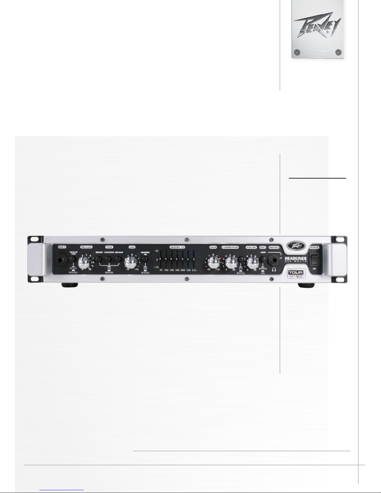
Headliner Front Panel
1
1
2
INPUT
3
5
4
6
8
7
9
11
10
12
14
13
15
16
17
1/4" Instrument Input. WARNING: Never plug the output of a power amplier into the input jacks. Damage
may occur to both units.
ACTIVE/PASSIVE PICKUP SWITCH
2
This switch is included so you can choose the appropriate setting for your instrument. The gain structure of
the amplier is modied to accommodate both active or passive pickup congurations.
3
PRE GAIN
This knob controls input level of the instrument.
4
BRIGHT SWITCH
This button provides a 10 dB boost to frequencies above 1kHz. To activate, press the switch to its “ON”
position.
5
CONTOUR
This button boosts highs and lows while simultaneously cutting mid tones, producing a "scooped" sound.
CRUNCH SWITCH
6
This button engages a crunch effect, simulating the classic overdriven tube amp sound. When using the
crunch feature, turning the tweeter off on your cabinet will result in a more authentic overdriven tone.
7
LOW
This knob provides a shelving tone control for low frequencies and provides cut/boost of +/-15 dB. The
center point is at. The center frequency is 50 Hz. The -3 dB shelf corner frequency is 100Hz.
8
EQ BYPASS
This button removes the graphic equalizer from the audio chain. When this switch is in the "Bypass"
position, the amp will respond as if the graphic equalizer is set at.
9
GRAPHIC EQUALIZER
These sliders provide precise tone control through the constant-Q, seven-band equalizer. Each band may be
boosted or cut 15 dB.
10
HIGH
This knob provides a shelving tone control for high frequencies and cut/boost of +/-15dB. The center point
is at and the frequency is 8 KHz. The -3dB; the shelf corner frequency is 5 KHz.
11
COMPRESSOR
Rotating this knob clockwise will increase the amount of compression in the signal chain.
16
Page 6

Headliner Rear Panel
18
12
13
14
19
21
20
22
23
COMPRESSOR ON/OFF SWITCH
This button switches the compressor on and off.
VOLUME
This knob controls the overall volume of the amplier.
DDT™ (Distortion Detection Technique)
This button prevents power amplier clipping that can damage speakers. Although this feature can be
activated or bypassed by this switch, Peavey® recommends the DDT stay enabled for optimum system
performance.
25
24
HEADPHONE OUTPUT
15
1/4" headphone output for personal monitoring.
16
DDT INDICATOR LIGHT
When DDT is enabled, the Protect/Clip LED will ash when DDT is triggered. This is normal. However,
if the LED is constantly illuminated, the gain level needs to be reduced to prevent possible equipment
damage. When DDT is defeated, the LED becomes a clip indicator. The DDT LED indicator is also a fault
indicator. If the amp is overheating, this LED will light up red and the amp will produce no sound. In this
case, the user needs to stop playing and allow the cooling fan to cool the amp down before continued
use. When the amp has returned to normal operating temperature, the light will turn green again. Also,
the user needs to verify that they are not exceeding the 4 ohm load limit and that the cooling vents are
free from obstruction. The other fault condition is when the output short protection is activated either
by a shorted speaker cable or by exceeding the 4 ohm load limit. If the LED stays red all the time, the
amplier needs to be taken to an authorized Peavey service center immediately for service.
17
POWER SWITCH
To apply power to the unit, ip the switch to the “ON” position. The green LED will illuminate, indicating
that power is being supplied.
Caution: The Power switch in this unit does not break both sides of the primary mains.
Hazardous energy can be present inside the chassis even when the Power switch is in the
"OFF" position.
18
AC POWER INLET:
This is the receptacle for an IEC line cord, which provides AC power to the unit. Connect the line cord to
this connector to provide power to the unit.
Never break off the ground pin on any equipment. It is provided for your safety. If the outlet used does
not have a ground pin, a suitable grounding adapter should be used, and the third wire should be
grounded properly. To prevent the risk of shock or re hazard, always make sure that the amplier and
all associated equipment is properly grounded.
17
Page 7

19
Meridian, MS 39301
Peavey Electronics Corp.
P. O. Box 2898
Title:
DCBA
1
2
3
4
NOTCH
EQ
LO
HI
Graphic EQ
HI PASS
HI PASS
LO PASS
2
1
SHELVING EQ
CONTOUR
PAD
INPUT
BRIGHT
PRE GAIN
POWER AMPLIFIER
STEREO HEADPHONE JACK
HEADPHONE AMPLIFIER
POST GAIN
FX SEND
FX RETURN
GROUND LIFT
COMPRESSOR
CRUNCH CIRCUIT
HEADLINER FUNCTIONAL BLOCK DIAGRAM
SPEAKER OUTPUTS
BALANCED DI
PRE/POST EQ
2
3
4
1
HEADLINER_BLOCK
EXTERNAL SPEAKER OUTPUT
One 2-pin twist-lock powered speaker output, paralleled with 1/4" powered speaker output (20).
1/4" EXTERNAL SPEAKER OUTPUT
20
1/4" powered speaker output, paralleled with 2-pin twist-lock powered output (19).
21
FOOTSWITCH JACK
Plug your Headliner footswitch into this 1/4" jack. The footswitch controls the crunch effect and
the compressor on/off. NOTE: The crunch and compressor buttons MUST be engaged to operate
with the footswitch. The part number for the TNT/Headliner footswitch is 03008010.
EFFECTS LOOP
22
The Send Jack provides a preamp output that may be used to drive slave ampliers and external effects processors. The Return Jack provides a power amp input for the last effect in the chain. NOTE:
When using the unit as a slave power amplier, the Return Jack should be used as the input.
DIRECT INTERFACE (DI)
23
This built-in, balanced Direct Interface is used to send a buffered, signal to an external mixer.
DI PRE/POST SWITCH
24
This button toggles the DI output from pre EQ to post EQ.
GROUND LIFT
25
This button is provided to prevent a ground loop that may result in "hum" noise. When depressed
(IN position), Ground Lift is engaged.
Tour Series Headliner Head Block Diagram
18
Page 8

Tour™ Series Headliner™ Head Specications
Tour Series Headliner Head
NOTE: All specications tested with
mains voltage maintained at nominal
level.
Line Voltage:
100vac to 240vac 50/60 Hz universal
power supply
CAUTION: Do not switch line voltage
while unit is powered on. Doing so may
cause damage to unit.
Typical Power Consumption = 100W
Power Amplier Specications:
Protection:
DDT™ speaker protection with defeat
switch
Short circuit protection
Thermal protection circuit
Current limit protection circuit
DC output protection circuit
Input Sensitivity (signal into return
jack with master volume set to 5):
7.32 dBu
Power Output:
All measurements with no more than
1% THD + N
8 ohms 200 watts (40.0 VRMS)
4 ohms 300 watts (34.6 VRMS)
Headphone Amplier Specications:
Stereo 8 ohm minimum load
Power Output:
All measurements with no more than
1% THD + N
8 ohms 250 mW (1.41 VRMS) x 2
Preamplier Specications:
Settings for the Following
Measurements (unless stated
otherwise):
PRE GAIN = 5 (12 o’clock)
BRIGHT = out
CONTOUR = out
CRUNCH = out
LOW = 0 (12 o’clock)
HIGH = 0 (12 o’clock)
GRAPHIC EQ = All sliders set to center
GRAPHIC EQ SWITCH = out
COMPRESSION = OUT
POST GAIN = 10 (fully CW)
™
DDT
= Active
Input Sensitivity (input selector set to
passive):
Nominal Input = -17.8 dBu
Minimum Input = -40.9 dBu
Maximum Input = 1.3 dBu (maximum
signal at input before clipping)
Input Sensitivity (input selector set to
active):
Nominal Input = -3.80 dBu
Minimum Input = -31.3 dBu
Maximum Input = 10.2 dBu (maximum
signal at input before clipping)
D.I. XLR Output:
Balanced output driven pre-EQ by
buffered instrument signal Foot
Switch Jack:
Ground switching type, TRS phone
plug (T = compressor, R = crunch, S =
ground)
Weight:
12 lbs. / 5.4 Kg
Dimensions (h x w x d):
(h x w x d): 2.813in / 7.14cm x
17.375in / 44.13cm x 12.500in
Features and specifications subject to change without notice.
All specifications tested with mains voltage maintained at nominal level.
19
Page 9

NOTES:
48
Page 10

NOTES:
Features and specifications subject to change without notice.
Peavey Electronics Corporation • 5022 Hartley Peavey Drive • Meridian • MS • 39305
(601) 483-5365 • FAX (601) 486-1278 • www.peavey.com • ©2011• EX000129
49
Page 11

PEAVEY ELECTRONICS CORPORATION LIMITED WARRANTY
Effective Date: 09/15/2010
What This Warranty Covers
Your Peavey Warranty covers defects in material and workmanship in Peavey products purchased and serviced in the U.S.A. and Canada.
What This Warranty Does Not Cover
The Warranty does not cover: (1) damage caused by accident, misuse, abuse, improper installation or operation, rental, product modification or neglect; (2) damage occurring
during shipment; (3) damage caused by repair or service performed by persons not authorized by Peavey; (4) products on which the serial number has been altered, defaced or
removed; (5) products not purchased from an Authorized Peavey Dealer.
Who This Warranty Protects
This Warranty protects only the original purchaser of the product.
How Long This Warranty Lasts
The Warranty begins on the date of purchase by the original retail purchaser. The duration of the Warranty is as follows:
Product Category Duration
Guitars/Basses, Amplifiers, Preamplifiers, Mixers, Electronic Crossovers and Equalizers 2 years *(+ 3 years)
Drums 2 years *(+ 1 year)
Enclosures 3 years *(+ 2 years)
Digital Effect Devices and Keyboards and MIDI Controllers 1 years *(+ 1 year)
Microphones 2 years
Speaker Components 1 year
(incl. Speakers, Baskets, Drivers, Diaphragm Replacement Kits and Passive Crossovers)
Tubes and Meters 90 Days
Cables Limited Lifetime
AmpKit Link, Xport, Rockmaster Series, Strum’n Fun, RetroFire, GT & BT Series Amps 1 year
[* Denotes additional Warranty period applicable if optional Warranty Registration Card is completed and returned to Peavey by original retail purchaser within 90 days of purchase.]
What Peavey Will Do
We will repair or replace (at Peavey’s discretion) products covered by Warranty at no charge for labor or materials. If the product or component must be shipped to Peavey for
Warranty service, the consumer must pay initial shipping charges. If the repairs are covered by Warranty, Peavey will pay the return shipping charges.
How To Get Warranty Service
(1) Take the defective item and your sales receipt or other proof of date of purchase to your Authorized Peavey Dealer or Authorized Peavey Service Center.
OR
(2) Ship the defective item, prepaid, to Peavey Electronics Corporation, International Service Center, 412 Highway 11 & 80 East, Meridian, MS 39301. Include a detailed description
of the problem, together with a copy of your sales receipt or other proof of date of purchase as evidence of Warranty coverage. Also provide a complete return address.
Limitation of Implied Warranties
ANY IMPLIED WARRANTIES, INCLUDING WARRANTIES OF MERCHANTABILITY AND FITNESS FOR A PARTICULAR PURPOSE, ARE LIMITED IN DURATION TO THE LENGTH OF
THIS WARRANTY.
Some states do not allow limitations on how long an implied Warranty lasts, so the above limitation may not apply to you.
Exclusions of Damages
PEAVEY’S LIABILITY FOR ANY DEFECTIVE PRODUCT IS LIMITED TO THE REPAIR OR REPLACEMENT OF THE PRODUCT, AT PEAVEY’S OPTION. IF WE ELECT TO REPLACE THE
PRODUCT, THE REPLACEMENT MAY BE A RECONDITIONED UNIT. PEAVEY SHALL NOT BE LIABLE FOR DAMAGES BASED ON INCONVENIENCE, LOSS OF USE, LOST PROFITS,
LOST SAVINGS, DAMAGE TO ANY OTHER EQUIPMENT OR OTHER ITEMS AT THE SITE OF USE, OR ANY OTHER DAMAGES WHETHER INCIDENTAL, CONSEQUENTIAL OR
OTHERWISE, EVEN IF PEAVEY HAS BEEN ADVISED OF THE POSSIBILITY OF SUCH DAMAGES.
Some states do not allow the exclusion or limitation of incidental or consequential damages, so the above limitation may not apply to you.
This Warranty gives you specific legal rights, and you may also have other rights which vary from state to state.
If you have any questions about this Warranty or services received or if you need assistance in locating an Authorized Service Center, please contact the Peavey International
Service Center at (601) 483-5365.
Features and specifications are subject to change without notice.
Logo referenced in Directive 2002/96/EC Annex IV
(OJ(L)37/38,13.02.03 and defined in EN 50419: 2005
The bar is the symbol for marking of new waste and
is applied only to equipment manufactured after
13 August 2005
Page 12

Logo referenced in Directive 2002/96/EC Annex IV
(OJ(L)37/38,13.02.03 and defined in EN 50419: 2005
The bar is the symbol for marking of new waste and
is applied only to equipment manufactured after
13 August 2005
U.S. customer warranty registration.
Page 13

 Loading...