

Page 1

GPS2600 - 3500
Larry Cook
Peavey Electronics Instructor
1
1
Page 2
Initialization Protection
TM
2
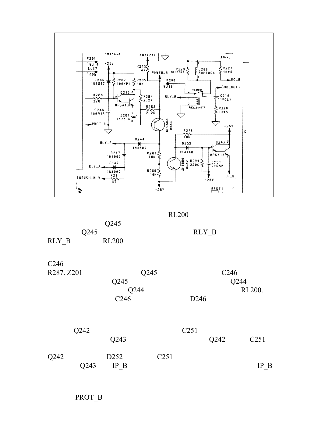
When power is applied to the GPS3500, RL200 isolates the amplifier from the
speakers. Initially, Q245 has zero volts between the base emitter and will be
off. Since Q245 is off Q244 will be off and RLY_B will be low. While
RLY_B is low the RL200 will be off.
C246 will initially have zero volts across it. It will start charging through
R287. Z201 is a 5 volt zener so Q245 will not turn on until C246 charges to
about 6.5 volts. Once Q245 turns on the voltage at the base of Q244 is reduced
to about 5 volts. This turns Q244 on and applies about 24 volts to RL200.
Note during power off C246 discharges through D246 so the relay opens
quick.
Initially Q242 is off and the voltage across C251 is zero. There will be –20
volts at the base of Q243 and it will be off. While Q242 is off, C251 will
charge up and IP_B will increase to +25 volts. Once the relay is energized,
Q242 will turn on. D252 will force C251 to discharge only through the base
emitter of Q243 and IP_B will slowly decrease to zero volts. When IP_B is
high the input is muted. When it is low the input is not muted.
Notice if PROT_B goes low the relay will open and the cycle starts over.
2
Page 3
Initialization Protection
TM
3
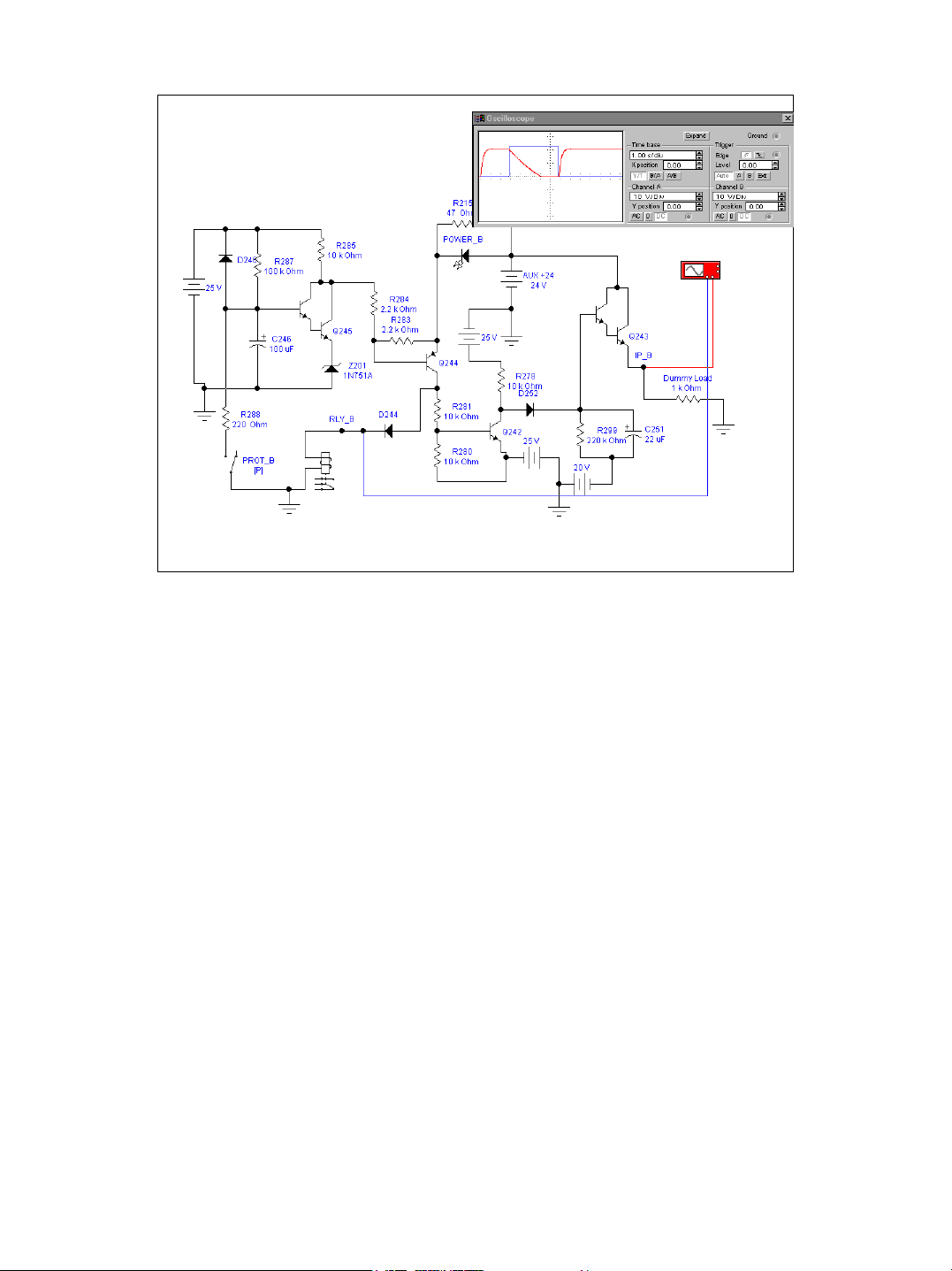
When power is applied to the GPS3500, RL200 isolates the amplifier from the
speakers. Initially, Q245 has zero volts between the base emitter and will be
off. Since Q245 is off Q244 will be off and RLY_B will be low. While
RLY_B is low the RL200 will be off.
C246 will initially have zero volts across it. It will start charging through
R287. Z201 is a 5 volt zener so Q245 will not turn on until C246 charges to
about 6.5 volts. Once Q245 turns on the voltage at the base of Q244 is reduced
to about 5 volts. This turns Q244 on and applies about 24 volts to RL200.
Note during power off C246 discharges through D246 so the relay opens
quick.
Initially Q242 is off and the voltage across C251 is zero. There will be –20
volts at the base of Q243 and it will be off. While Q242 is off, C251 will
charge up and IP_B will increase to +25 volts. Once the relay is energized,
Q242 will turn on. D252 will force C251 to discharge only through the base
emitter of Q243 and IP_B will slowly decrease to zero volts. When IP_B is
high the input is muted. When it is low the input is not muted.
3
Page 4
Thermal Protection
DC Protection
4
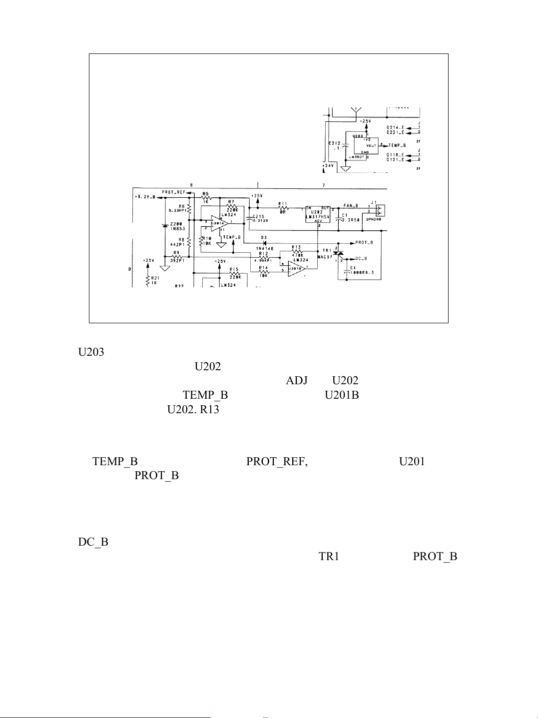
U203 is a precision centigrade temperature sensor. It’s output will be 10mv for
each degree centigrade. U202 is a three terminal voltage regulator. It’s output
is 1.25 volts higher than the voltage on the ADJ pin. U202 directly controls the
speed of the fan. The TEMP_B signal is applied to U201B which controls the
fan speed through U202. R13 provides hysteresis. The fan will stop at a lower
temperature than it started.
If TEMP_B becomes greater than PROT_REF, then the output of U201 will
go low and PROT_B will go low. This will cause the initialization protection
to open the relay and system initialization will start over after the heat sink
cools.
DC_B is feedback from the output before the relay. Subsonic frequencies and
DC on the output of sufficient strength will cause TR1 to turn on and PROT_B
will go low. This will cause the initialization protection to open the relay and
system initialization will start over after the fault condition is removed.
4
Page 5
Short Circuit
Load Fault Protection
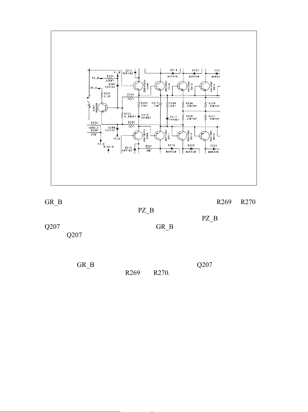
GR_B is normally about +25 volts. Excessive current through R269 or R270
will indicate a load fault or short. PZ_B is feedback from the output. If there is
an output voltage (load fault condition) the voltage from PZ_B will prevent
Q207 from turning fully on. In this case GR_B would reduce the input. Under
a short, Q207 would turn on and the amp will enter the protect mode. This
happens through SH_B and PROT_B not shown here.
TM
5
Notice that GR_B will often be a series of pulses since Q207 will be controlled
by the peak currents through R269 and R270.
5
Page 6
DDT and Others
6
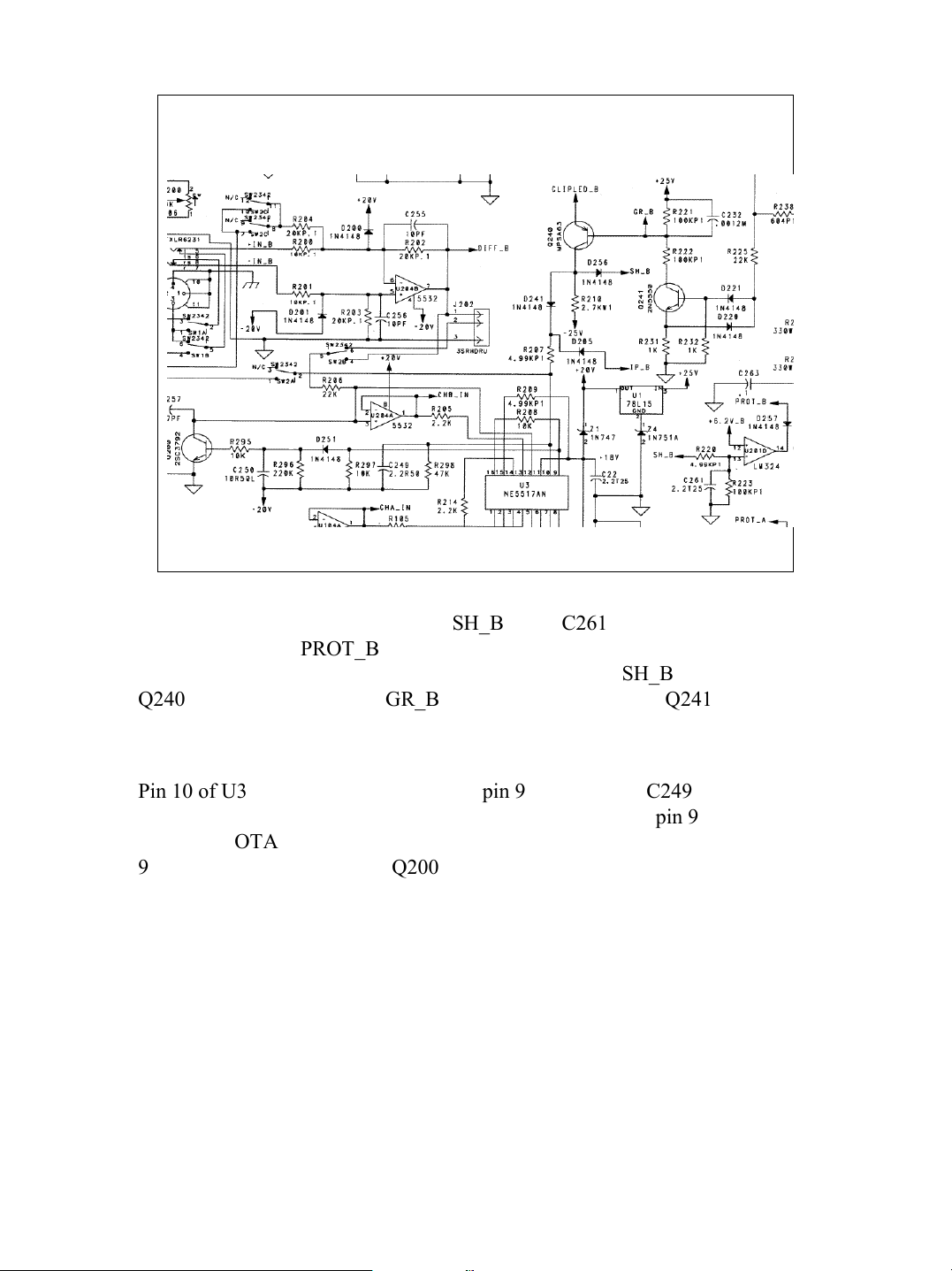
If the frequency and peak voltage of SH_B cause C261 to charge up to greater
than 6.2 volts then PROT_B will go low an the amp will go into protect mode.
Initialization will start over if that condition is removed. SH_B originates from
Q240 which is controlled by GR_B (short and load fault) and Q241 which
detects clipping.
Pin 10 of U3 is the input to a buffer and pin 9 is the output. C249 smoothes the
signal providing a DC level instead of pulses. The output on pin 9 controls the
gain of the OTA reducing the input appropriately. If the average voltage on pin
9 becomes large enough then Q200 will turn on and mute the input.
6
 Loading...