

Page 1
Page 2

A
Intended to alert the user to the presence of uninsulated “dangerous voltage” within the product’s enclosure
that may be of sufficient magnitude to constitute a risk of electric shock to persons.
A
Intended to alert the user of the presence of important operating and maintenance (servicing) instructions in the
literature accompanying the product.
CAUTION:
Risk of electrical shock - DO NOT OPEN!
CAUTION:
To reduce the risk of electric shock, do not remove cover. No user serviceable parts inside. Refer servicing to
qualified service personnel.
WARNING:
To prevent electrical shock or fire hazard, do not expose this appliance to rain or moisture. Before using this
appliance, read the operating guide for further warnings.
Production MixerTM 1000
Please read this entire manual before connecting the mixer to your audio system.
CAUTION:
Do not use spray
cleaner for
any slide control as this will wash out vital lubircants
and shorten
component
life.
Parts Inventory:
In order to read this manual, you will have already unpacked the unit. You should have:
One
PMTM
1000 mixer unit
One 39 V AC UL listed Table top power supply (packed separately)
Please retain the packing material for future use.
2
Page 3
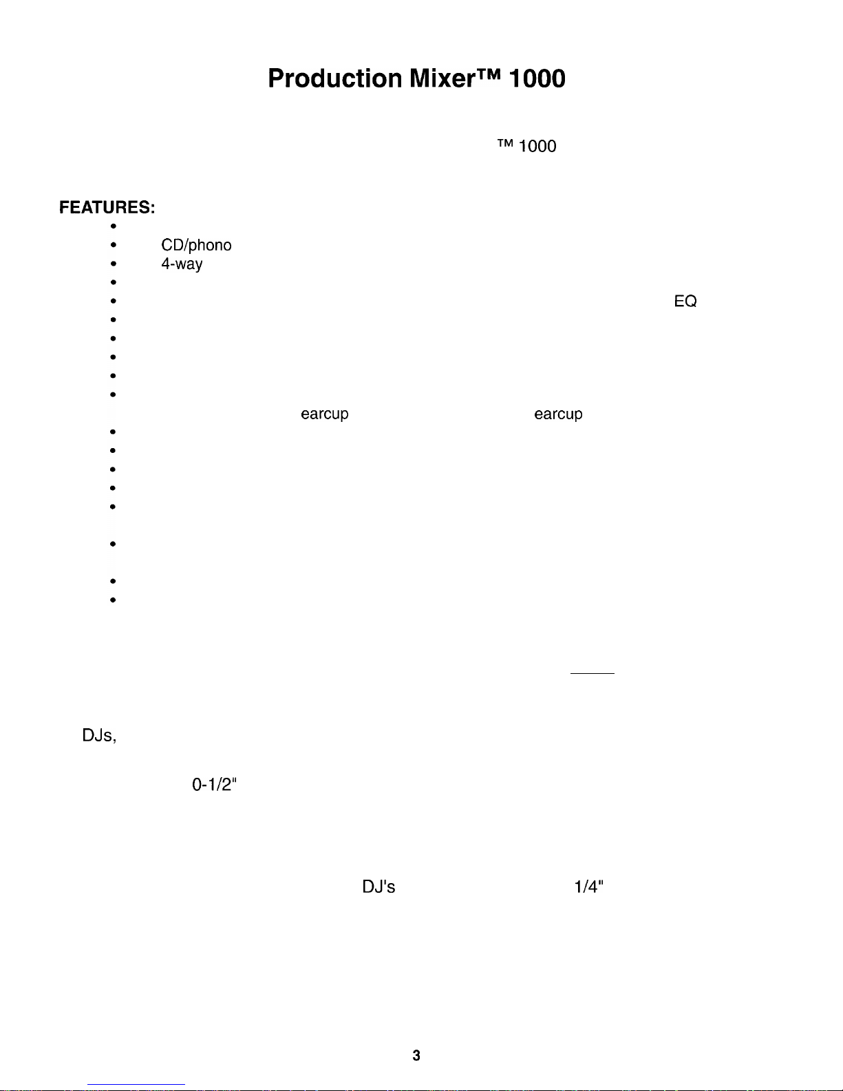
Production MixerTM 1000
Thank you for purchasing the Peavey Production
Mixer
TM
1000
professional DJ mixing unit.
When used in accordance with this manual, your new DJ mixer will give years of good service.
FEATURES:
Monitor Facility with separate switch for mic in/out
CD/phone switches on all four phono music inputs
4-way assignable crossfade switches
Eight music inputs (4 stereo RCA inputs)
Selectable program effects loop to add echo, reverb, etc., or more graphic
EQ
Separate, selectable mic effects loop common to both mic inputs
Individually-selectable headphone cueing for each music channel
Selectable automatic voice-over
Manual push-to-talk voice-over button
Cueing selector to listen to stereo program output, stereo channel cueing, or
channel cue in right
earcup
and program output in left
earcup
Individually adjustable levels for program and channel cueing facilities
Built-in gooseneck XLR light socket
45 mm heavy-duty (field replaceable) crossfade slider
Power on/off switch with LED indicator
High slew-rate, super low-noise op amps are used throughout the entire mixer’s
circuitry
60 mm high-quality Alps slide faders are used on all channels and master level
control
Level trim controls on all music inputs
Channel assignable/defeatable crossfade facility
The Production Mixer 1000 multi-media entertainment mixer is a brand new addition to
Peavey’s line of premium quality DJ equipment. It is an all-American made, high-quality, rug-
ged, and professional DJ mixer.
DJs,
rap recording artists, and specialist DJ equipment dealers were closely involved in
active consultancy during and throughout each design stage.
Housed in a 1
O-1/2”
x 19” rugged steel chassis, the PM 1000 boasts a truly remarkable
array of much preferred DJ features like: four individual music channels; eight music inputs,
four of which are individually switchable to phono or CD; fully assignable/defeatable
crossfader; three-band EQ on each channel; and built-in gooseneck XLR light socket. Low
impedance, phantom powered front/rear panel-mounted microphones deliver fast, positive
connect and disconnect facilities for the
DJ’s
mic; and rear-mounted
l/4”
input is provided for
Hi-Z microphones.
Because vinyl is becoming very difficult to obtain and CDs are playing a much larger part as
the preferred DJ music medium, each phono input on this DJ mixer has an individual slide
switch that changes the input from vinyl to CD (or back again) quickly and easily. Therefore, as
vinyl becomes even more scarce, every phono (record deck) input may also be used for CD
players.
3
Page 4
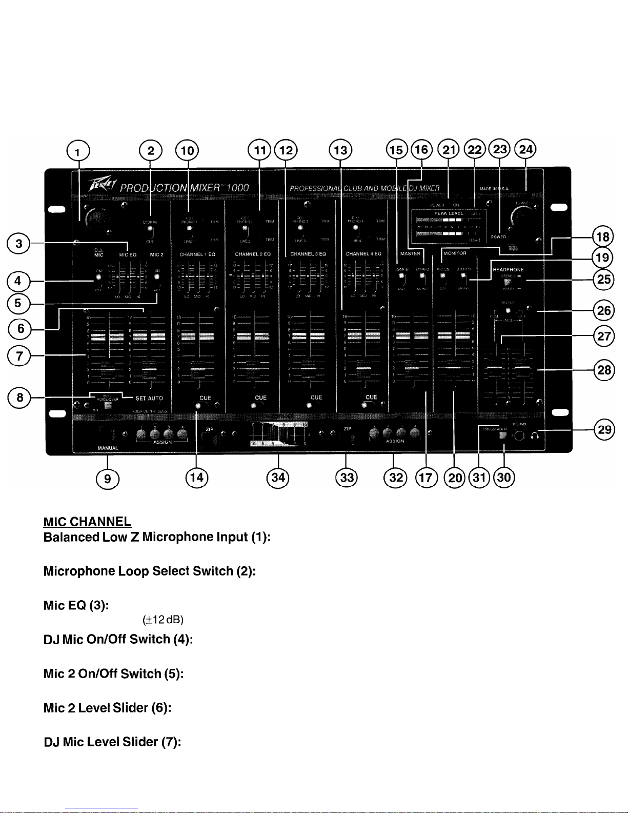
PM 1000 Front Panel:
MIC
CHANNEL
Balanced Low
2
Microphone Input (1):
For use with a low impedance microphone or low level source equipped with an XLR connector.
Microphone Loop Select Switch (2):
When the switch is in the out position, the microphone loop is bypassed.
Mic EQ (3):
Active tone controls (k12
dB)
that vary the Lo, Mid, and Hi frequencies.
DJ Mic On/Off Switch (4):
DJ Mic is “live” when the switch is in the “on” position.
Mic 2 On/Off Switch (5):
Mic 2 is “live” when the switch is in the “on” position.
Mic 2 Level Slider (6):
A mono slider that determines the output level of the second microphone channel.
DJ Mic Level Slider (7):
A mono slider that determines the output level of the microphone channel.
4
Page 5
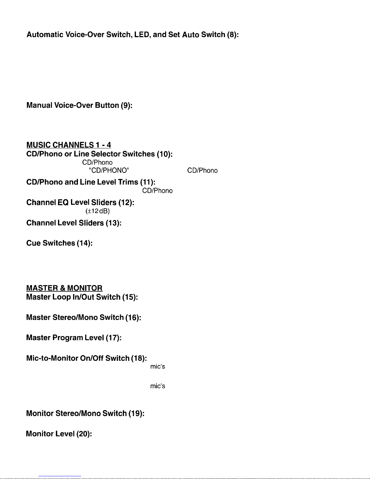
Automatic
Voice-Over Switch, LED, and Set Auto Switch (8):
When this switch is in the “on” position, presentation of signals on either of the two microphone inputs, such
as announcements, etc., automatically drops the level of the music. Placing this switch in the “off” position
defeats this automatic facility. The LED will illuminate when the Voice-Over is active. Use the SET AUTO
controls as follows:
HOLD:
Adjusts length of time music is attenuated when auto voice-over is active.
DEPTH:
Adjusts level that music is attenuated when auto voice-over is active.
SENS:
(Sensitivity Control) Adjusts level of mic signal needed to activate auto voice-over circuitry.
Manual Voice-Over Button (9):
When pressed, this drops the music level enabling the DJ to talk over the music. Press to activate and
release to inactivate.
MUSIC CHANNELS I- 4
CD/Phone or
Line Selector Switches (10):
Allows selection of CD/Phone (L and R) or Line (L and R) inputs. The “LINE” position of this switch selects
the line input and the “CD/PHONO” position selects the CD/Phone input.
CD/Phone
and Line Level Trims (11):
Allows independent level adjustment of CD/Phone and line inputs.
Channel EQ Level Sliders (12):
Active tone controls
(f12 dB)
that vary the Lo, Mid, and Hi frequencies.
Channel Level Sliders (13):
A stereo slider that determines the output level of each particular music channel.
Cue Switches (14):
When placed in the right-hand position, each of these switches routes a channel’s signal to the cue system.
When placed in the left-hand position, each of these switches routes the channel’s signal out of the cue
system.
MASTER & MONITOR
Master Loop In/Out Switch (15):
When the switch is in the out position, the program loop is bypassed.
Master Stereo/Mono Switch (16):
Used to select mono or stereo operation in the Master section.
Master Program Level (17):
A stereo slider that determines the overall program level from Channels 1, 2, 3, 4, and the Mic channel.
Mic-to-Monitor On/Off Switch (18):
When the switch is in the “off” position, the
mic’s
signals are not fed through the monitor system. This is to
enable in-booth program material to be played and cued without feedback from the booth microphones.
When the switch is in the “on” position, the
mic’s
signals are fed through the monitor system. In this position,
the monitor system can be used to set the levels for a second music zone, e.g. a second dance floor or
background level for another zone, instead of being used for monitoring the DJ booth.
Monitor Stereo/Mono Switch (19):
Used to select mono or stereo operation in the monitor section.
Monitor Level (20):
A stereo slider that determines the overall monitor level from Channels 1, 2, 3, 4, and the Mic channel.
5
Page 6

Power LED (21):
Illuminates when AC power is being supplied to the unit.
LED Arrays (Left & Right) (22):
Two calibrated LED arrays are provided to visually indicate program output levels.
Power Switch (23):
Depress to the “on” position to turn the unit on.
Light Socket (24):
A 2-pin XLR jack is provided for connecting an optional gooseneck mixer lamp for illumination in adverse
lighting conditions. Peavey accessory lamp number ML-3 is a suitable gooseneck mixer lamp for this purpose.
HEADPHONE
Headphone Mono/Stereo Selection Switch (25):
This switch enables the operator to select either stereo or mono signals through the headphones. This
feature is particularly useful when the operator uses single-cup mono headphones.
CAUTION: Although you can select mono by using this switch, only
l/4”
stereo Tip-Ring-Sleeve jacks
should be used for headphones. Do not use a mono (Tip-Sleeve) jack to connect your headphones as this
will short out one of the headphone amplifiers and damage to the mixer may result.
PGM/Cue Select Switch (26):
When placed in the PGM (program) position, this switch delivers headphone monitoring of all stereo program material present at the outputs. The PGM/Cue “add” position delivers monitoring of the program
(output) material to the left earcup of the headphones. Material present on the cue bus (see Cue switches
[14])
may be heard in the right earcup of the headphones.
The Cue position delivers cue material “in stereo” to the headphones’ left and right earcups.
Program Headphone Level Fader (27):
Sets PGM sound levels that are available at the headphone socket when PGM is selected.
Cue
Headphone
Level Fader (28):
Sets Cue sound levels that are available at the headphone socket when Cue is selected.
Headphone Jack
(29):
Stereo headphones patched in at this point will allow monitoring of program material or cueing of the system. NOTE: Do not use mono headphones with this system (see number 25 for explanation).
CROSSFADER
Crossfader
In/Out Switch (30):
In the out position, the crossfader is bypassed.
Crossfader
LED (31):
Indicates whether or not crossfader is active.
Crossfader
Assign Switches (32):
The left-hand switch assigns channel 1, 2, 3, or 4 to the left-hand side of the crossfader. The right-hand
switch assigns channel 1, 2, 3, or 4 to the right-hand side of the crossfader.
ZIP (33):
Allows instant transition from left assign to right assign (or vice versa) regardless of crossfader position.
Crossfader
Slider (34):
A stereo slider that delivers crossfade capability between channels 1, 2, 3, or 4 according to the position of
the two crossfade assign switches.
6
Page 7

Blending and crossfading between all channels is accessible by assigning channels 1, 2, 3, or 4 for left- and
right-hand positioning of the crossfader slider. For example:
Left-hand ASSIGN switch set to channel #3 will access channel 3 when the crossfade slider is in the
left-hand position.
Right-hand ASSIGN switch set to channel #2 will access channel 2 when the crossfade slider is in
the right-hand position.
NOTE: It is useful to remember that when the crossfade slider is set to its center (number 5) position, both
channels assigned to the left- and right-hand crossfade positions will be at equal levels. You may then
simply use the channel level controls to crossfade between the two assigned channels and ignore the
crossfade, leaving it set in the center position. This is a more “European” technique of crossfading and is
preferred by some
DJs.
REAR PANEL:
Power Input (35):
External 39 V AC 1 amp power supply should be plugged in at this point. Turn unit power switch off (number
23).
Plug the small jack at the end of the power supply lead into the 39 V AC socket on the rear of the unit.
Plug the power supply provided with your PM 1000 into a main AC wall power receptacle. Turn unit power
switch on (number 23) to activate unit.
CAUTION: Use only the power supply that is provided with this product. If the original power supply
must be replaced, consult your dealer or the factory for assistance in obtaining the correct replace-
ment. Failure to use the correct power supply could result in fire or shock hazard, extensive circuit
damage, decreased performance, or non-operation.
Monitor Outputs (36):
Monitor output left and right jacks are provided for monitoring main Left and Right signals. The output at this
point should be patched to the stereo power amplifiers driving the monitor speaker system.
NOTE: It is often useful to use the monitor outputs to drive an independent sound system for another audio
zone such as a second dance floor or background music elsewhere within the venue.
Program Outputs (37):
Main output left and right jacks are provided for the main (program) output. The output at this point should
be patched to the stereo power amplifiers driving the main speaker system.
7
Page 8

Program Loop - Send (Out) and Return (In) (38):
Send and return jacks are provided for stereo patching of external effects devices, graphic equalizers, or
other signal processing devices to the program and monitor channels.
Chassis Ground Lug (39):
Grounds from other pieces of equipment should be connected at this point to minimize ground loop possibili-
ties between power amps, outboard signal processing units, turntables, etc.
CD/Phone
Switches - Channels 1 - 4 (40):
Selects the CD/Phone inputs to accept input from either a magnetic phono cartridge (Phono [switch down]
position) or a CD or other line source (CD [switch up] position).
CD/Phone
Inputs - Channels 1 - 4 (41):
Left and right inputs are provided for output from turntables or CDs, depending on position of the CD/Phone
’
switch (40) on each channel.
Line Outputs - Channels 1 - 4 (42):
Left and right inputs are provided for “line level” signals from tape decks, CDs, or other sources.
Hi-Z Mic Input (43):
For use with high impedance microphones or high level sources equipped with a phone plug.
Mic 2 Input (44):
For use with low impedance microphones or low level sources equipped with a male XLR connector.
Mic Loop - Send (Out) and Return (In) (45):
Send and return jacks are provided for mono patching of external effects devices, graphic equalizers, or
other signal processing devices at the microphone channel.
Page 9

SPECIFICATIONS
Summarv of
Functions:
Input sensitivity measured with master fader at
8 Stereo inputs - 4 CD/Phone and 4 Line
4-way assignable crossfader
2 Microphone channels with 3-band EQ and
automatic voice-over facility with on/off switch.
Switchable stereo headphone jack
15 V phantom power for electret
mics
45 mm stereo Crossfade slider
One 16 V AC mixer lamp socket
nominal and channel fader at maximum.
0 dBV = 1 volt RMS
CD/Phone
Inputs: @ 1 kHz
Phono Position (RIAA):
Nominal Input Level: -40 dBV (11
mV)
Input Sensitivity:
-50 dBV (3
mV)
Input Impedance: 47 K ohms
ZIP - left assign and right assign
Microphone Functions:
Two Low Z balanced mic inputs with phantom
power
3-band EQ
+I2 dB
Automatic voice-over selector switch
Voice-over Hold, Depth, and Sensitivity controls
Manual voice-over button
Mic On/Off switch (Mic 1 and Mic 2)
60 mm mono level sliders
Effects Loop In/Out switch
Channels
1-4
Functions
(each channel):
l
Stereo (RIAA) Phono input switchable to CD
l Stereo Line input
l CD/Phone selector switch
l
Stereo selector switch for Line input or CD/
Phono input
l 60 mm stereo level slider
l
Independent Cue switch for each channel
l 3-band EQ
+I2 dB
l CD/Phone and Line Trim controls
Master Section:
l Stereo IO-segment LED display
l 60 mm stereo program level slider
l Stereo/Mono switch
l Effects Loop In/Out switch
Monitor Section:
l Mic On/Off switch
l 60 mm stereo monitor level slider
l Stereo/Mono switch
Cue Section:
l Cue Headphone level
l Program Headphone level
l Cue/Program Headphone selector switch
l Stereo/Mono Headphone switch
CD Position:
Nominal Inout Level: 0 dBV (1
V)
Input Sensitivity: -10 dBV
i.316
V)
Input Impedance: 47 K ohms
Line Inputs:
Nominal Input Level:
0 dBV (1 V)
Input Sensitivity: -10 dBV (.316 V)
Input Impedance: 200 K ohms
Mic Inputs (Low-Z):
Nominal Input Level: -50 dBV (3
mV)
Input Sensitivity: -60 dBV (1
mV)
Input Impedance: 3 K ohms
Mic Inputs (Hi-Z):
Nominal Input Level: -38 dBV (14
mV)
Input Sensitivity: -48 dBV (4
mV)
Input Impedance:
IOKohms
Program Outputs:
Nominal Output Level:
0 dBV (1 V)
Maximum Output Level:
+20 dBV (IO V)
Minimum Load Impedance:
2 K ohms
Mic Talkover:
Attenuation (Voice-Over switch enabled or Auto-
matic Voice-Over enabled): -3 dB to -25 dB refer-
enced to the output level
Frequency Response:
Phono Inputs (RIAA):
+O/-3
dB (20 Hz to 20
kHz)
Line/CD Inputs:
+0/-l
dB (20 Hz to 20
kHz)
Headphone:
+0/-l
dB (20 Hz to 20
kHz)
Distortion:
1
kHz @
Nominal Output: < .05%
Signal to Noise Ratio:
Phono:
>
70 dB
Line/CD:
>
88
dB
Due to our efforts for constant improvements,
features
and specifications listed herein are subject to change without notice.
9
Page 10

. . . . . . . . .
. _ _ _ .
.........
.........
. . . . . . . . . . . . . . . . . . . . . . . . . ., . . : . . . . . . . . . . . . . . . . . . . . . . . .
i ; i ii;:
; i
; ii;;
; :;:i
i i .
i:
i :
::
i
: i:::
.
i:
::::
. ; ii;:
. . .
c . . . . . .
>....j . .
j
..i..;..; . . . . . . . . . . . . . . .
i ; i;j;;
; ;
iii:
~~
;
::
::i:
. i i
ii;;
. j
i.ii
; :
:
:
: :
. .
. . .
..I .
. . . . > . . . . . . . .
;...i...;...;
. . . . . . . . . . . . . .
: ~~~~
7~~
: : : I::
. . . . .
. . . . .
. . . . .
>. . ..
=
\
/
. . .
. . . . .
. . . . .
. . . . .:
. . .
..j
. . . . . . . . . . . . . . . . . . . . . . . . . . . . .
:
. .
,.
. .
:
. . . . . . . . . . . . . .
i I
.
.
iii!
: :
*
ii::
.I;
.
i i
* ii..
. i
i.
. . i
I
. . . . . .
s......
>...j
. . . .
j..i..<..i
. . . . . . . . . . .
j ; ii)ii
i i ;;;i
i :
i ii;;
:-r;i--:i-:-i
~
. . . .
..:..
. .
..:
. . . . . . . . . .
~
. . . . . . . . . . .
;...;
. .
i..;..;..;
. . . . . .
.
~.,~..~.~
i I:
i i :
.i
i:::
.ii
.
i i
. :
::
. . . . . .
i :
. . . . . .
..I
. . . . .
f
. . . .
I..;...:..;
. . . . . . . . . . . . . .
.
; i ii;;
. i
ii;i
. i ii
. . :
;
. ; i.
i i
.
:i::
.
i:::
.: ::
. . . . . . .
*
. . . . . . . . . . . . . . .
:..I...:..:
. . . . . . . . . . . . . .
. . .
‘:
. .
..j
. . . . . . . . . . . . . . . . . . . . . . . . . . ,. . . . . . . .
i j i
1 : :
; I
i i :
. i ;
. . . . . . . . .f . . . j . . . . F...'..
i j i
i i
i i
; i
ir-l.--
: :
. . . . . . j...<..
i ii
i :
~
i i i
;
: j
; :
i i .
. ; !
i i .
. . . . . . . ... . . . . . . . . . f . . . . . . . . . . . .
1..
ii
i
. i i
:i: i
:
i:
i
: i .
: : :
.a . . . . . . . . . . . . . . . . . . . . . .
..: . . . .:..
. . . . . . . . . . . . . . .
1Ok
ZOk
100
lk
Page 11

tlflOd
13NNVH3
33HHl
13NNVH3
0M.l
13NNVH3
3N0
13NNVH3
Page 12

PM
1000
Patch Diagram
One device to
each pair of
outputs
Power Amp and loudspeakers
-or-
Tape Recorder
One device to each pair of
CD/phone
inputs per channel
All lines are Stereo
unless otherwise noted
Mono lines
to and from
Graphic
EC&
Delay unit,
Reverb, etc.
Page 13

For further information on other Peavey products,
ask your Authorized Peavey Dealer for the
appropriate Peavey catalog/publication:
Bass Guitars
Guitars
Bass Amplification
Guitar Amplification
Sound Reinforcement Enclosures
Microphones
Keyboards
DJ
Lighting
Mixers, Powered/Non-Powered
Accessories/Cables
Effects Processors
AxcessTM
Wear
The Peavey
BeatTM
Monitor8 Magazine
Key
IssuesTM
Low
DownTM
PMTM
Magazine
13
Page 14

THIS LIMITED WARRANTY VALID ONLY WHEN PURCHASED AND REGISTERED IN THE UNITED STATES OR CANADA. ALL EXPORTED PRODUCTS
ARE SUBJECT TO WARRANTY AND SERVICES TO BE SPECIFIED AND PROVIDED BY THE AUTHORIZED DISTRIBUTOR FOR EACH COUNTRY.
Ces clauses de garantie ne
sont
vaiables qu’aux
Etats-Unis
et au Canada. Dans tour
les
autres pays,
les
clauses de garantie et de maintenance
sont
fixees par le distributeur national et assuree par
lul
seion la legislation envigueur.
l l
Diese Garantie
ist
nur in den USA and Kanada gultig. Alle Export-
Produkte sind der Garantie und dem Service des lmporteurs des jewelligen Landes unterworfen.
.* Esta
garantia es
valida
solamente cuando
el
product0
es
comprado
en E.U. continentales o en Canada. Todos
10s productos
que
Sean
comprados en el extranjero,
estan
sujetos a
las
garantias y
servicio que cada distribuidor autorizado determine y ofrezca en
10s
diferentes paises.
PEAVEY ONE-YEAR LIMITED
WARRANTY/REMEDY
PEAVEY ELECTRONICS CORPORATION (“PEAVEY”) warrants this product, EXCEPT for covers, footswitches, patchcords, tubes and meters, to be free from
defects in material and workmanship for a period of one (1) year from date of purchase, PROVIDED, however, that this limited warranty is extended only to the
original retail purchaser and is subject to the conditions, exclusions, and limitations hereinafter set forth:
PEAVEY
90-DAY
LIMITED WARRANTY ON TUBES AND METERS
If this product contains tubes or meters, Peavey warrants the tubes or meters contained in the product to be free from defects in material and workmanship for
a period of ninety (90) days from date of purchase; PROVIDED, however, that this limited warranty is extended only to the original
retall
purchaser and is also
subject to the conditions, exclusions, and limitations hereinafter set forth.
CONDITIONS, EXCLUSIONS, AND LIMITATIONS OF LIMITED WARRANTIES
These limited warranties shall be void and of no effect, if:
a.
The
first
purchase of the product is for the purpose of resale; or
b.
The original retail purchase is not made from an AUTHORIZED PEAVEY DEALER; or
c.
The product has been damaged by accident or unreasonable use, neglect, improper service or maintenance, or other causes not arising out of defects in
material or workmanship; or
d.
The serial number affixed to the product is altered, defaced, or removed.
In the event of a defect In material and/or workmanship covered by this limited warranty, Peavey will:
a.
In the case of tubes or meters, replace the defective component without charge.
b.
In other covered cases (I.e., cases involving anything other than covers, footswitches, patchcords, tubes or meters), repair the defect
in
material or
workmanship or replace the product, at Peavey’s option; and provided, however, that, in any case, all costs of shipping, if necessary, are paid by you, the
purchaser.
THE WARRANTY REGISTRATION CARD SHOULD BE ACCURATELY COMPLETED AND MAILED TO AND RECEIVED BY PEAVEY WITHIN FOURTEEN (14)
DAYS FROM THE DATE OF YOUR PURCHASE.
In order to obtain service under these warranties, you must:
a.
Bring the defective item to any PEAVEY AUTHORIZED DEALER or AUTHORIZED PEAVEY SERVICE CENTER and present therewith the ORIGINAL
PROOF OF PURCHASE supplied to you by the AUTHORIZED PEAVEY DEALER in connection with your purchase from him of this product.
If the DEALER or SERVICE CENTER is unable to provide the necessary warranty service you will be directed to the nearest other PEAVEY AUTHORIZED
DEALER or AUTHORIZED PEAVEY SERVICE CENTER which can provide such service.
OR
b. Ship the defective item, prepaid, to:
PEAVEY ELECTRONICS CORPORATION
International Service Center
326 Hwy. 11 & 80 East
MERIDIAN, MS 39301
including therewith a complete, detailed description of the problem, together with a legible copy of the original PROOF OF PURCHASE and a complete return
address. Upon Peavey’s receipt of these items:
If the defect is remedial under these limited warranties and the other terms and conditions expressed herein have been complied with, Peavey will provide the
necessary warranty service to repair or replace the product and will return it, FREIGHT COLLECT, to you, the purchaser.
Peavey’s liability to the purchaser for damages from any cause whatsoever and regardless of the form of action, including negligence, is
limited
to the actual
damages up to the greater of $500.00 or an amount equal to the purchase price of the product that caused the damage or that is the subject of or
IS
directly related
to the cause of action. Such purchase price will be that In effect for the specific product when the cause of action arose. This limitation of liability will not apply to
claims for personal injury or damage to real property or tangible personal property allegedly caused by Peavey’s negligence. Peavey does not assume liability for
personal injury or property damage arising out of or caused by a non-Peavey alteration or attachment, nor does Peavey assume any responsbility for damage to
interconnected non-Peavey equipment that may result from the normal functioning and maintenance of the Peavey equipment.
UNDER NO CIRCUMSTANCES WILL PEAVEY BE LIABLE FOR ANY LOST PROFITS, LOST SAVINGS, ANY INCIDENTAL DAMAGES, OR ANY
CONSEQUENTIAL DAMAGES ARISING OUT OF THE USE OR INABILITY TO USE THE PRODUCT, EVEN IF PEAVEY HAS BEEN ADVISED OF THE
POSSIBILITY OF SUCH DAMAGES.
THESE LIMITED WARRANTIES ARE IN LIEU OF ANY AND ALL WARRANTIES EXPRESSED OR IMPLIED, INCLUDING, BUT NOT LIMITED TO, THE
IMPLIED WARRANTIES OF MERCHANTABILITY AND FITNESS FOR A PARTICULAR USE; PROVIDED, HOWEVER, THAT IF THE OTHER TERMS AND
CONDITIONS NECESSARY TO THE EXISTENCE OF THE EXPRESSED, LIMITED WARRANTIES, AS HEREINABOVE STATED, HAVE BEEN COMPLIED
WITH, IMPLIED WARRANTIES ARE NOT DISCLAIMED DURING THE APPLICABLE ONE-YEAR OR NINETY-DAY PERIOD FROM DATE OF PURCHASE OF
THIS PRODUCT.
SOME STATES DO NOT ALLOW LIMITATION ON HOW LONG AN IMPLIED WARRANTY LASTS, OR THE EXCLUSION OR LIMITATION OF INCIDENTAL
OR CONSEQUENTIAL DAMAGES, SO THE ABOVE LIMITATIONS OR EXCLUSIONS MAY NOT APPLY TO YOU. THESE LIMITED WARRANTIES GIVE YOU
SPECIFIC LEGAL RIGHTS, AND YOU MAY ALSO HAVE OTHER RIGHTS WHICH MAY VARY FROM STATE TO STATE.
THESE LIMITED WARRANTIES ARE THE ONLY EXPRESSED WARRANTIES ON THIS PRODUCT, AND NO OTHER STATEMENT, REPRESENTATION,
WARRANTY, OR AGREEMENT BY ANY PERSON SHALL BE VALID OR BINDING UPON PEAVEY.
In the event of any modification or disclaimer of expressed or implied warranties, or any limitation of remedies, contained herein conflicts with applicable law,
then such modification, disclaimer or limitation, as the case may be, shall be deemed to be modified to the extent necessary to comply with such law.
Your remedies for breach of these warranties are limited to those remedies provided herein and Peavey Electronics Corporation gives this
limited
warranty only
with respect to equipment purchased in the United States of America.
INSTRUCTIONS - WARRANTY REGISTRATION CARD
1.
Mail the completed WARRANTY REGISTRATION CARD to:
PEAVEY ELECTRONICS CORPORATION
POST OFFICE BOX 2898
MERIDIAN, MISSISSIPPI 39302-2898
a. Keep the PROOF OF PURCHASE. In the event warranty service is required during the warranty period, you will need this document. There
will
be no
identification card issued by Peavey Electronics Corporation.
2.
IMPORTANCE OF WARRANTY REGISTRATION CARDS AND NOTIFICATION OF CHANGES OF ADDRESSES:
a. Completion and mailing of WARRANTY REGISTRATION CARDS - Should notification become necessary for any condition that may require correction,
the REGISTRATION CARD will help ensure that you are contacted and properly notified.
b. Notice of address changes - If you move from the address shown on the WARRANTY REGISTRATION CARD, you should notify Peavey of the change of
address so as to facilitate your receipt of any bulletins or other forms of notification which may become necessary in connection
with
any condition that may
require dissemination of information or correction.
3.
You may contact Peavey directly by telephoning (601)
483-5365.
14
Page 15

IMPORTANT SAFETY INSTRUCTIONS
WARNING: When using electric products, basic cautions should always be followed, including the following.
1.
2.
3.
4.
5.
6.
Read all safety and operating instructions before using this product.
All safety and operating instructions should be retained for future reference.
Obey all cautions in the operating instructions and on the back of the unit.
All operating instructions should be followed.
7.
8.
9.
This product should not be used near water, i.e., a bathtub, sink, swimming pool, wet basement, etc.
This product should be located so that its position does not interfere with its proper ventilation. It should not be placed flat against a
wall or placed in a built-in enclosure that will impede the flow of cooling air.
This product should not be placed near a source of heat such as a stove, radiator, or another heat producing amplifier.
Connect only to a power supply of the type marked on the unit adjacent to the power supply cord.
Never break off the ground pin on the power supply cord. For more information on grounding, write for our free booklet “Shock
Hazard and Grounding.”
10.
11.
12.
13.
14.
Power supply cords should always be handled carefully. Never walk or place equipment on power supply cords. Periodically check
cords for cuts or signs of stress, especially at the plug and the point where the cord exits the unit.
The power supply cord should be unplugged when the unit is to be unused for long periods of time.
If this product is to be mounted in an equipment rack, rear support should be provided.
Metal parts can be cleaned with a damp rag. The vinyl covering used on some units can be cleaned with a damp rag or an ammonia-
based household cleaner if necessary. Disconnect unit from power supply before cleaning.
Care should be taken so that objects do not fall and liquids are not spilled into the unit through the ventilation holes or any other
openings.
15.
16.
17.
18.
This unit should be checked by a qualified service technician if:
a.
The power supply cord or plug has been damaged.
b.
Anything has fallen or been spilled into the unit.
C.
The unit does not operate correctly.
d.
The unit has been dropped or the enclosure damaged.
The user should not attempt to service this equipment. All service work should be done by a qualified service technician.
This product should be used only with a cart or stand that is recommended by Peavey Electronics.
Exposure to extremely high noise levels may cause a permanent hearing loss. Individuals vary considerably in susceptibility to noise
induced hearing loss, but nearly everyone will lose some hearing if exposed to sufficiently intense noise for a sufficient time.
The U.S. Government’s Occupational Safety and Health Administration (OSHA) has specified the following permissible noise level
exposures.
Duration Per Day In Hours
Sound Level
dBA,
Slow Response
8
90
6
92
4
95
3
97
2
100
1
l/2
102
1
105
l/2
110
l/4
or less
115
According to OSHA, any exposure in excess of the above permissible limits could result in some hearing loss.
Ear plugs or protectors in the ear canals or over the ears must be worn when operating this amplification system in order to prevent a
permanent hearing loss if exposure is in excess of the limits as set forth above. To ensure against potentially dangerous exposure to high
sound pressure levels, it is recommended that all persons exposed to equipment capable of producing high sound pressure levels such as
this amplification system be protected by hearing protectors while this unit is in operation.
SAVE THESE INSTRUCTIONS!
15
Page 16

A
Features and specifications subject to change without notice
CD
01995
Peavey Electronics Corporation 711 A Street / Meridian, MS 39301 / U.S.A. / (601
#I30302335
)
483-5365 I Fax 486-l 278
Printed in U.S.A.
9/95
 Loading...