

Page 1
Page 2
A
the presence
uninsulated “dangerous voltage” within the
enclosure
sufficient magnitude
constitute
risk
electric shock to
A
the presence
important operating and maintenance (servicing) instructions
the
product.
CAUTION: Risk
electrical shock
CAUTION:
reduce the risk
electric shock, do not remove
user serviceable
Refer servicing
personnel.
WARNING:
prevent electrical shock or fire hazard, do not expose
appliance
rain or moisture. Before using this
A
propdsito de alertar
usuario de la presencia de “(voltaje) peligroso” que
tiene
la caja
product0
puede tener una magnitud suficiente coma para constituir riesgo
A
simbolo tiene
propdsito
alertar
usario
la presencia
instruccones importantes
operacidn
la literatura
viene con
producto.
PRECAUCION: Riesgo de corrientazo
PRECAUCION: Para disminuir
riesgo de corrientazo,
la cubierta.
hay piezas adentro que
usario pueda
Deje todo mantenimiento tecnicos calificados.
ADVERTENCIA: Para evitar corrientazos
peligro de incendio,
deje expuesto lluvia
humedad este aparato
usar este
lea mas advertencias en la guia
operation.
A
symbole est utilise pur indiquer
l’utilisateur la presence
l’inttrieur de
produit de tension non-isolee
suffisante pour constituer un risque
choc
A
symbole est utilise pour indiquer
l’utilisateur
ou
trouvera
instructions
dans la litterature accompagnant
produit.
ATTENTION: Risques de choc
ATTENTION: Afin de reduire
risque
choc
enlever
couvercle.
trouve
reparee
Confier
un personnel qualifie.
AVERTISSEMENT: Afin de prevenir
risques
decharge
feu,
cet appareil
la pluie
Avant d’utiliser cet appareil, lisez
avertissements suppltmentaires situ& dans
guide.
1
Symbol
den Anwender vor unisolierten gefahrlichen
innerhalb
Gehauses warnen, die
Ausreichender Starke
einen elektrischen Schlag verursachen
kbnnen.
A
Symbol
den Benutzer
wichtige Instruktionen
der Bedienungsanleitung aufmerksam machen, die
VORSICHT: Risiko
Elektrischer
Nicht offnen!
VORSICHT:
das Risiko eines elektrischen Schlages
vermeiden, nicht die Abdeckung enfernen.
befinden
darin, die vom Anwender repariert werden konnten. Reparaturen nur von qualifiziertem Fachpersonal
ACHTUNG:
einen elektrischen Schlag oder Feuergefahr zu vermeiden, sollte dieses Gerat nicht dem Regen oder
Inbetriebnahme unbedingt die Bedienungsanleitung lesen.
Page 3
800s POWER AMPLIFIER OWNERS MANUAL
Congratulations on your purchase of the new
stereo power amplifier. This latest version is the most advanced
ever, using state-of-the-art switching power supply technology to deliver high fidelity and rock solid performance in a two-
rack-space unit that weighs just under 23 pounds. This new design retains the extended performance capability of the old
providing impressive two ohm output power capability, and maintaining the old 4
8 ohms ratings with
awesome industry standards for power bandwidth, slew rate and distortion specifications. The new
design also reflects
a significant improvement in damping factor specifications. Following is the new
specs:
l 420 W RMS into 4 ohms...600 W RMS into 2 ohms (per channel)
l 840 W RMS into 8 ohms... 1200 W
into 4 ohms (bridged)
l
compression with LED indicators and defeat switch
l Slew Rate: 40 V/microsecond, stereo mode, each channel
l Power Bandwidth:
Hz to 50 KHz
4 ohms,
rated power
l Total Harmonic Distortion: Less than
rated power
l Hum and Noise: 100
below rated power, unweighted
l Damping Factor: Greater than 7000
4 ohms,
Hz, each channel
The heavy transformer is replaced by an extremely reliable switching power supply that uses proven half-bridge topology
to provide 1,700 watts peak power from a high-efficiency
design. The supply has a thermal monitor system with
proportional fold-back which prevents a total shut-down at extreme operating temperatures. The new
retains the
Peavey patented
compression system which virtually eliminates any possibility of clipping. The new back panel
design now includes plug-in modules for both inputs and outputs offering flexible patching features and various connector
choices. Two variable speed DC fans provide tremendous cooling capability upon demand.
THE AMP FEATURES
l Two rack space height-less than 17” depth
l Under 23 Ibs...switching power supply
l Plug-in modular inputs
l Dual XLR (bal)/phone
with “thru” output per channel
Universal three-way crossover module
l Plug-in modular outputs
l Dual phone jack and
binding post per channel
l Dual
Quick Connect with patchable
of pin-outs
l Modular construction
l Replaceable channel and power supply modules
l Significant/y reduced mains turn-on surge
l Two variable speed DC
noise levels
l
input attenuator
each channel
l DDT activation LED
power LED each channel
l Recessed rear
DDT
bridge switch
l /EC mains connector
THE DIGITAL POWER SUPPLY
l Ultra reliable
Robust
l Uses proven Ha/f-Bridge topology-fewer parts
l 1,700 W peak power...25% over-design
l
design...high efficiency
l Light weight-cost effective
l Massive aluminum heat
thermal
l Thermal monitor system with fold-back feature-no shut-down except fault
l Effective, low-cost filter design.../ow conducted EM/
l Fully operational down to 85 V AC Mains (Domestic)...
V AC Mains (Export)
We hope you will find your new
not to be just another power amplifier, but the most exciting power amplifier you
have ever purchased. Please read over this owners manual carefully. It will help you to use this exciting product most
effectively.
Page 4
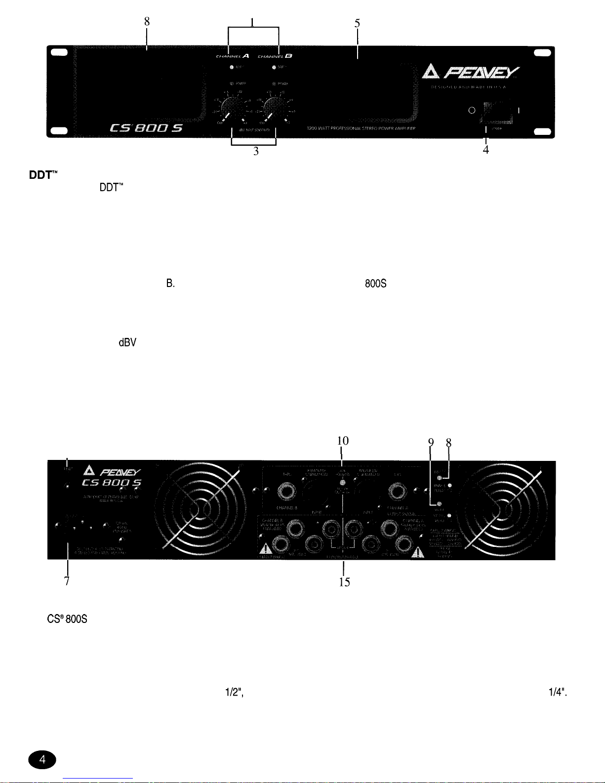
FRONT PANEL
ACTIVE LED (1)
Illuminates when
Compression is taking place. With the ENABLE/DEFEAT switch in the DEFEAT position, the LED indicates
when clipping distortion is occurring.
POWER LED (2)
Illuminates when AC power is being supplied to the amp and the associated channel is operational. Illumination is delayed slightly
during the power-up cycle due to the transient suppression/thermal fault circuitry. If either channel experiences fault conditions or
exceeds the safe operating temperature limits, then that channel will shut down, and the associated power LED will go out indicating
such conditions exist. Also, whenever the BRIDGE mode is selected, the power LED on channel B is defeated (OFF), just as if there
were a fault condition on channel
This provides a positive indication that the CS 800s is in bridge mode.
INPUT SENSITIVITY (3)
Maximum power amplifier input gain (minimum sensitivity) is achieved at the full clockwise setting. This setting yields maximum
mixer/system headroom. A setting of less than full clockwise will yield lower system noise at the expense of headroom. Calibration
indicates sensitivity in
necessary to attain the full output power rating.
POWER SWITCH (4)
Depress to “on” position to power up unit.
AIR EXHAUST PORT (5)
This is where the hot air from the heat sinks exhaust from the amplifier. Any restriction or blockage could cause excessive operation
temperatures and the unit could shut down!
6
I
REAR PANEL
CIRCUIT BREAKER (6)
The
800s uses a circuit breaker in place of the main fuse. This breaker is provided to limit the current to the digital power supply
and thereby protect it from overheating and possible destruction due to fault conditions in the amplifier. The trip current value has
been carefully chosen to allow continuous power output performance while still providing adequate protection for the power supply.
Normally this breaker should not trip unless there is a fault in the amplifier circuitry that draws excessive mains current. However,
abnormal conditions such as a short circuit on either or both channels or continuous operation at overload or clipping, especially into
2 ohm load will cause the breaker to trip. If this occurs, simply reset the breaker and correct the cause of the overload. When tripped,
the button on the breaker will be outward nearly
and can be reset by pushing inward. A normal reset button length is about
If this “thermal” type breaker does trip, then simply pushing the button back in will reset it after waiting a brief period of time to allow it
to cool. If the breaker trips instantly when you attempt to reset it, the unit should be taken to a qualified service center for repair.
Page 5
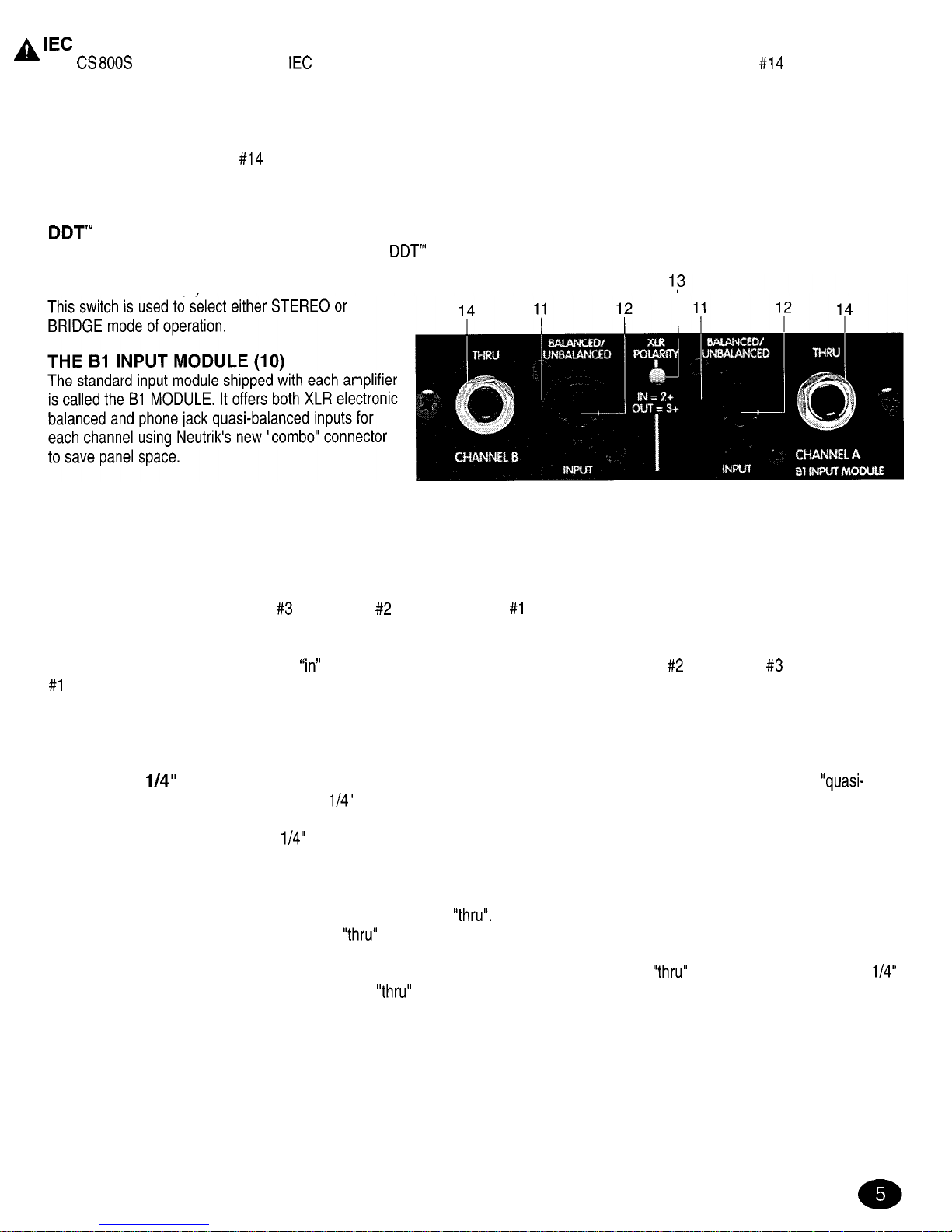
MAINS POWER CONNECTOR (7)
The
800s is fitted with a universal
connector. Into this connector one should always insert a heavy duty
AWG 3
conductor line cord with a conventional AC plug with a ground pin. This line cord should be connected to an independent mains circuit
capable of supporting at least 15 amps continuously or greater. This is particularly critical for sustained high power applications. If the
socket used does not have a ground pin, a suitable ground lift adapter should be used and the third wire grounded properly. Never
break off the ground pin on the 3 conductor line cord. The use of extension cords should be avoided, but if necessary, always use a
three-wire type with at least a
AWG wire size. The use of lighter wire will severely limit the power capability of this amplifier.
Always use a qualified electrician to install any necessary electrical equipment. To prevent the risk of shock or fire hazard, always be
sure that the amplifier is properly grounded.
SWITCH (8)
This switch is used to either ENABLE or DEFEAT the
compressor.
MODE SWITCH (9)
The female XLR inputs (11)
are connected to dual OP AMP circuitry which offers very low noise and extremely high common mode rejection ratio to minimize
outside interference!
Between the two XLR connectors is a recessed switch (13) which allows the user to select the desired polarity (phase) of the
XLR inputs. This switch is a push-push type and a small diameter “tool” is required to select the desired position. Set to the out
(default) position, the polarity is pin
positive, pin
negative, and pin #I ground. This is the polarity found on most Peavey power
amplifiers. Although this is not the world “standard” (IEC) polarity, it was chosen by Peavey more than 20 years ago, and thus we
offer this polarity to be consistent with products both past and present. If this amplifier is used with other competitive products which
use the IEC standard polarity, then the
position of switch (13) should be selected yielding pin
positive, pin
negative, and pin
power amplifier must be in phase with any other loudspeaker enclosures associated with other power amps. If one loudspeaker
system were to “push” while the other “pulls”, then a serious sound “cancellation” could result. Changing the setting of the polarity
switch has the same effect as reversing the polarity of the loudspeaker connections at the output.
The female
phone jack input (12) in the center of the “combo” connectors are also connected to a unique
balanced” input circuitry. When used, these
jacks are not “chassis grounded” but connected to ground through a relatively low
impedance circuit which is part of a “ground loop” elimination circuitry associated with the input. This feature will normally allow “hum
free” operation when relatively short
cable patches are made to this input from various outputs on this amp and other equipment
that share the same rack with this amp. This “quasi-balanced” circuit is “automatic”, and is virtually invisible in normal usage. It can
not be defeated.
Each channel also has a female phone jack (14) labeled “thru”. This jack offers a very flexible patching capability. When the
XLR input connectors (11) are used, then this “thru” jack is the output of the electronic balanced input circuitry, and as such can be
used as a “line out” to connect to the other input jack on this amplifier or other amps in the same rack. Thus one balanced mixer feed
can be connected to the amp via the XLR connector and then further distributed locally via the “thru” jack. Alternatively, when the
phone jack input (12) is used as the input, then the “thru” jack becomes a “bridged” input to it (similar to a Y-cord), again allowing this
input signal to be patched to the other input jack on this amplifier or other amps in the system.
Additional input modules are available from your authorized Peavey Dealer. Details of these modules and the installation instructions
can be secured from this source.
Page 6
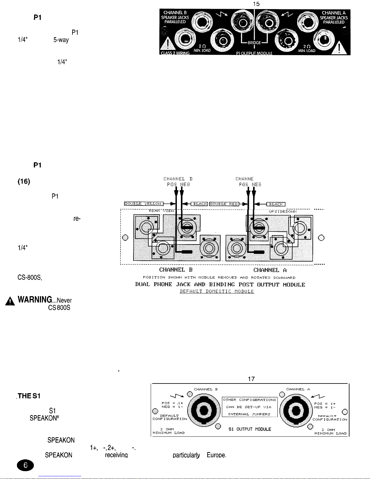
THE
OUTPUT MODULE (15)
The standard output module shipped with each
amplifier is called the
MODULE. It offers both dual
jacks and
binding post speaker outputs for
each channel. For each channel, the outputs are in
parallel, hence the speaker connection cables can be
terminated with
phone plugs, or banana plugs or stripped wires for use in the binding post terminals. For sustained high power
applications, the use of the binding post terminals are recommended; however, care must be exercised to assure the correct speaker
phasing. The red binding posts are the signal outputs from each channel, and the black binding posts are chassis ground. The red
binding post should be connected to the positive inputs of the associated loudspeakers. For bridge mode operation, only the red
binding posts are used, and the associated loudspeaker load is connected between the two red binding posts. The red binding post
associated with channel A should be considered the positive output for the system and thus should be connected to the positive input
of the associated loudspeaker system.
Regardless of what connections are used, the minimum parallel speaker load should always be limited to 2 ohms per channel or 4
ohms bridge mode for any application. Operation at loads of 4 ohms per channel or 8 ohms bridge mode is more desirable for
sustained operation applications due to the fact that the amplifier will run much cooler at this loading. Operation above 4 ohms per
channel and even open circuit conditions can always be considered safe; however, sustained operation at loads below 2 ohms could
result in temporary amplifier shut down due to the thermal limits fault circuitry.
THE
OUTPUT
MODULE REAR VIEW
This diagram shows the
wiring for the PI MODULE.
Note that the module itself is
upside down. This is the
desired position when
connecting this and any
other module. Once the
correct connections to the
spades are made, then
the module itself can be
rotated upward and inserted
into the rear panel of the
and the panel
screws replaced.
16
L
A
operate the
800s with
either the output or input modules removed. Operating in this manor will allow the air flow from the fans to escape from these
openings instead of flowing through the power amp and power supply components, and thereby not provide adequate cooling for
these components.
Following are several other module rear views of a different module and the various wiring schemes. The diagram above and the
ones following are provided so that these modules can be correctly wired. Always double check the wiring. A miswired module can
cause severe audio problems, and in the worse case, can cause loudspeaker degradation and failure. In all cases, the color-coded
wires are indicated. The double red and yellow wires are the power amp outputs and are not interchangeable. The black wires are the
power amp ground connections and are
interchangeable.
OUTPUT MODULE (17)
Another output module available for this amplifier
is called the
MODULE. This module offers
dual
Quick Connectors and a unique
patching capability to wire these connectors to
meet the particular application or loudspeaker
needs. The
is a four-wire connector
with the connections labeled
1 and 2
Depending upon the loudspeaker needs, these connections can be used in various
ways. The
connector is
wide acceptance earticularlv in
Page 7
THE
OUTPUT
MODULE REAR VIEW
LOW CURRENT
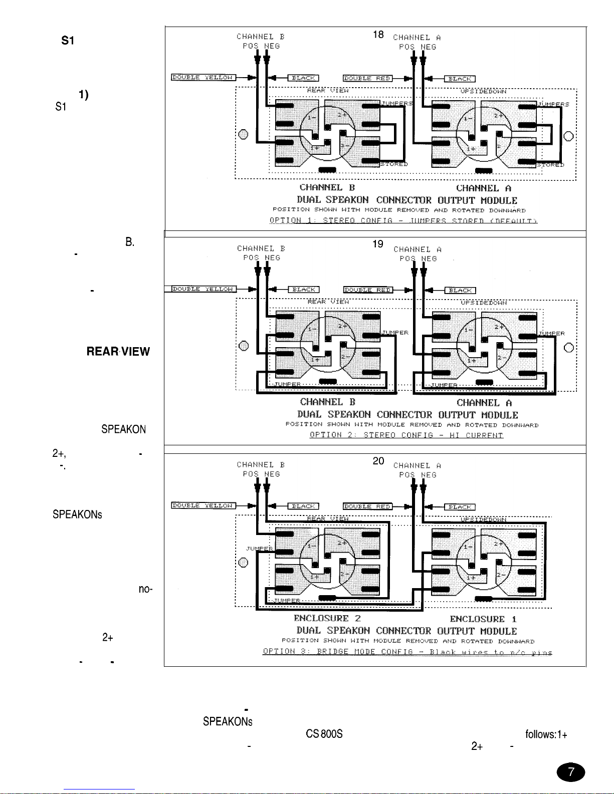
STEREO MODE (18)
(Option
This
module is shipped
wired as follows: lt as the
channel signal output and 1
as the channel chassis
ground. This is really the
defacto standard for most
low-to-medium power
loudspeaker systems. This
wiring allows one enclosure
to be connected to channel
A, and one enclosure to be
connected to channel
The
2 t and 2
connections are
simply not used in this
application! In this case the
2 t and the 2
spades are
used to “store” the jumper
cables for later usage.
THE Sl OUTPUT
MODULE REAR,VIEW
HIGH CURRENT
STEREO MODE (19)
(Option 2)
Many larger loudspeaker
systems use the full
capability of the
connector by paralleling 1 t
and
and paralleling 1
and 2
This wiring improves
the current handling
capability of the system and
reduces losses. Most “subs”
with
are wired
this way. This module can be
easily re-wired to this
configuration using the
supplied jumpers on the rear
of the module. Normally four
jumpers are plugged in a
connect configuration for
“storing”. In this case, one
jumper is connected
between 1 t and
and
another jumper is connected
between 1
and 2
for each
channel. This is a total of
four jumpers. The diagram (19) shows the wiring of the jumpers.
THE Sl OUTPUT MODULE REAR VIEW
BRIDGE MODE (20) (Option 3)
This module can be re-wired to allow the
to be the bridge outputs with both in parallel. This arrangement would allow for
example, two 8 ohm enclosures to be connected in parallel to the
800s in bridge mode. In this case the wiring is as
on
both connectors wired to channel A signal output; 1
on both connectors wired to channel B signal output;
and 2
on both
Page 8
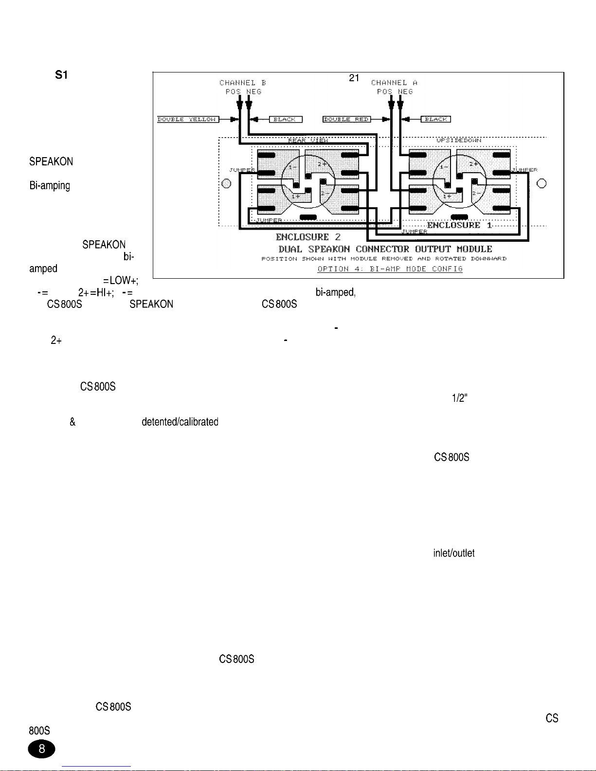
connectors not used; channel A and B chassis ground wires are not uses (plugged into isolated floating terminals)! This wiring
requires one jumper per channel for a total of two; the other two are stored! Again, a wiring diagram is included and check it carefully
before you proceed!
THE
OUTPUT
MODULE REAR VIEW
BI-AMP MODE (21)
(Option 4)
The final wiring
arrangement is really a
natural progression of the
capability with
it’s four wire connections.
is really the
preferred configuration for
most sound reinforcement
systems. It will be
discussed later in this
manual. The
pins used in the typical
loudspeaker
enclosure are: 1 t
1 LOW-;
2 HI-. With the above wiring arrangement, two
wired loudspeaker enclosures can be connected
to a
800s via the two
connectors. First, the
800s must be configured for bi-amp mode with each channel signal
supplied from a suitable crossover, and in this case the configuration is channel A is the “lows” and channel B is the “highs”. For this
one, the wiring is: 1 t on both connectors wired to channel A signal output; 1
on both connectors wired to channel A chassis ground
wire;
on both connectors wired to channel B signal output; 2
on both connectors wired to channel B chassis ground wire. This
configuration also requires two jumpers per channel for a total of four. Again, check the wiring of the module carefully!
INSTALLATION AND CONNECTION
The Peavey
800s commercial series power amplifier is designed for durability in commercial installations and the quality of
performance required in studio and home applications. The unit is a standard rack-mount configuration, 3
high and is cooled by
two variable speed internal fans. All the input and output connections are on the back panel. The front panel contains LED indicators
for power
DDT activation,
sensitivity controls, and a mains power switch.
INDUSTRIAL AND COMMERCIAL INSTALLATIONS
For commercial and other such installations where sustained high powered operation is required, the
800s should be mounted in
a standard EIA 19” rack. It is not necessary to leave rack space between each amplifier in the stack, since the fan pulls air in from the
rear and exhausts the hot air out the front. An adequate source of cool air must be provided for the amplifier when rack-mounted. The
internal fans must have a source of air that is not preheated by other equipment. If cool, the amplifier will start up in low-speed fan
operation, and will normally stay at low-speed operation unless sustained high power operating levels occur. As the amplifier heat
sinks heat up the automatic thermal sensing circuitry will increase the fan speed. Depending upon signal conditions and amp loading,
the fan speed may increase to a maximum value, or it may decrease to a minimum value. This situation is quite normal.
Inadequate cooling due to preheated air, a reduction of air flow caused by blockage of the amplifiers
ports, or severly
overloading the amp may cause the amplifiers thermal sensing system to temporary shut down that particular channel. This will be
indicated by the channel power LED on the front panel ceasing to illuminate. Depending upon available cooling air, operation will be
restored to that channel relatively quickly, and the power LED will then be illuminated. Corrective action should be taken to determine
the cause of the thermal shutdown. If the amplifier is not severely overloaded or shorted, and air flow is normal in and out of the unit,
steps should be taken to provide a cooler environment for all the amplifiers. As a general rule, the cooler electronic equipment is
operated, the longer its useful service life.
STUDIO AND HOME INSTALLATION:
In most low-to medium-power applications, the
800s can be mounted in any configuration. It is desirable that, if at all possible, the
unit be located at the top of an equipment stack. This will prevent possible overheating of any sensitive equipment by the hot air rising
from the power amplifier. As a general rule, most home and studio requirements will never cause maximum high speed fan operation.
If it does however, this may indicate that you have not taken the necessary steps to provide adequate cooling. Remember, closed up
in a cabinet, the
800s will have severe cooling problems, even at low power levels. Again, inadvertent short circuit or sustained
overloaded usage could also cause temporary thermal shutdown. Most home wiring and electrical circuits are only 15 amps. Two
Page 9
A
BRIDGE MODE:
The bridge mode on stereo amplifiers is often misunderstood as to the actual operation and usage. In basic terms, when a
channel amplifier is operated in bridge mode, it is converted into a single channel unit with a power rating equal to the sum of both
channel’s power ratings, at a load rating of twice that of the single channel rating. In this case the
800s is rated at 600 W RMS
per channel into 2 ohms. The bridge mode ratings are 1,200 W RMS into 4 Ohms (minimum load). The bridge mode operation is
accomplished by placing the mode switch into the bridge position, connecting the load between the red binding posts of each
channel, and then using channel A as the input channel. All channel B input functions are defeated.
Another application for bridge mode operation is to drive sound distribution systems in very large public address applications. In this
mode, the
power amplifier can actually drive 70-volt systems directly without using expensive matching transformers. The
real advantage of such an approach is primarily cost. 70-volt distribution systems are very common in domestic applications where
large numbers of relatively small loudspeakers are used for background music and paging. Such systems require the use of 70-volt
transformers at each loudspeaker. Another common use for the bridge mode is in subwoofer applications where very high output
power levels are required to reproduce extreme low frequencies. Such enclosures usually contain two or four loudspeakers to handle
the high power levels involved. For bridge mode usage, the enclosure impedance must be 4 or 8 ohms; never below 4 ohms! Also
make sure the enclosure can handle 1,200 watts reliably.
Peavey’s patented
compression system enables the sound man to maximize the performance of the amplifier/speaker
combination by preventing the power amp from running out of headroom (clipping). This compression system is activated by a unique
circuit that senses signal conditions that might overload the amplifier and reduce the amplifier’s gain when clipping is imminent. The
threshold of compression is clipping itself and no specific threshold control is used. This technique effectively utilizes every precious
watt available for the power amplifier to reproduce the signal while at the same time minimizes clipping and distortion, and thus
significantly reduces the potential of loudspeaker degradation and damage. The DDT system is automatic, hands-off approach to the
problem of power amplifier clipping.
Since the
800s power amplifier uses a circuit breaker for over-current protection, the DDT compression system plays even a
more important roll in the continuous performance by preventing each channel from clipping and overloading. Continuous operation at
clipping can cause the circuit breaker to trip, but with the DDT activated this problem is minimized. For this reason you should always
have the DDT compression system enabled.
SPECIFICATIONS
OUTPUT POWER: (Typical value, 120 V AC, 60 Hz)
Stereo mode, both channels driven
2 ohms, 1
1% THD, 600 W RMS per than
4 ohms, 1
1% THD, 420 W RMS per than
8 ohms, 1
1% THD, 260 W RMS per than
Bridge mode, mono
4 ohms, 1
1% THD, 1,200 WRMS
8 ohms, 1
1% THD, 840 WRMS
RATED OUTPUT POWER: (120
V AC, 60 Hz)
Stereo mode, both channels driven
4 ohms, 10 Hz to 20
0.03% THD, 400 W RMS per than
8 ohms, 10 Hz to 20
0.02% THD, 240 W RMS per than
POWER BANDWIDTH:
Stereo mode, both channels driven
rated power, 4 ohms,
THD
10 Hz to 50
TOTAL HARMONIC DISTORTION:
Stereo mode, both channels driven
10 Hz to 20
4 ohm rated output, Less than 0.03%
HUM
NOISE:
Stereo mode, both channels driven
Below rated output power, 4 ohms, Greater than 100
(30 kHz BW, unweighted)
DAMPING FACTOR:
Stereo mode, both channels driven
4 ohms,
100 Hz,
Greater
than 1,000
4
ohms,
10
Greater
than 400
INPUT SENSITIVITY
IMPEDANCE:
Input attenuator set
FCW
rated output power, 4 ohms, 1.4 V RMS
20k ohms unbalanced
CHANNEL VOLTAGE GAIN:
Input attenuator set
FCW
Stereo mode, 4 ohms, 29
Bridge mode, 8 ohms, 1
35
FREQUENCY RESPONSE:
Stereo mode, both channels driven
-1
1 W RMS, 4 ohms, 3 Hz to 60
-0.1 rated output, 4 ohms, 20 Hz to 20
SLEW RATE:
Stereo mode, each channel
Greater than 40
Bridge mode, mono, Greater than 80
SQUARE WAVE RESPONSE:
Stereo mode, 4 ohms, 80 V P-P output
100 Hz waveform tilt, Less than 5 volts
10 KHz waveform rise-time, Less than 2
(0% over-shoot)
PHASE DISTORTION:
Stereo mode, 4 ohms
rated power
20 Hz leading waveform
Less than 6 degrees
20 KHz lagging waveform
Less than 15 degrees
POWER CONSUMPTION:
Stereo mode, both channels driven
rated output power, 4 ohms, 10 A
120 V AC
COOLING SYSTEM:
Dual continuously variable speed DC fans
COMPRESSION SYSTEM -Automatic, switchable with LED indicator
DIMENSIONS &WEIGHT:
Height 3.50” (8.9 cm)
Width 19” (48.3 cm)
Depth 17” (43.2 cm)
Weight 23 Ibs
kg)
Specifications
to change without notice.
Page 10

MANUAL DEL PROPIETARIO DEL AMPLIFICADOR DE POTENCIA
800s
Lo felicitamos por la compra
nuevo amplificador de potencia estereofonico
800s. Esta version, la
reciente y avanzada
existente, utiliza la
palabra en tecnologia de
de estado
brindar
fidelidad y un
rendimiento
en una unidad que ocupa dos espacios de rack y pesa menos de
kg. Este nuevo
retiene la capacidad de rendimiento
del
anterior, con
impresionante potencia de
sobre 2 Q. Sin embargo, mantiene
especifi-
caciones
4 y 8
anteriores con excelentes caracteristicas normalizadas de
de
de potencia, velocidad de
y
El nuevo
refleja
una mejora considerable en
especificaciones del factor de
A continuation se
especificaciones del amplificador
800s:
l 420 Wef (potencia eficaz) sobre 4
y 600 Wef sobre 2
(por canal)
l 840 Wef sobre 8
y 1200 Wef sobre 4
(mode de puente)
l
con indicadores de LED e interruptor de desactivacidn
l Velocidad de
40
en modo estereofdnico, por canal
l Respuesta en frecuencia:
Hz a 50 kHz sobre 4
a la potencia nominal
l
armdnica total: menos de/ 403% a la potencia nominal
l Zumbido y ruido:
por
de la potencia nominal, sin ponderacidn
l Factor de amortiguamiento: mayor que
sobre 4
a 100 Hz, por canal
El pesado transformador se reemplaza por una fuente de
de
extremadamente
que utiliza la
probada topologia de medio puente
proporcionar 1700 W de potencia
gracias a un eficiente disetio con
(transistores
bipolares de compuerta aislada). La fuente cuenta con un sistema de monitoreo termico con limitation de corriente proportional, que
evita
apagado total a temperaturas de operation extremas. El nuevo amplificador
800s retiene
sistema de compresion
patentado
que elimina practicamente cualquier posibilidad de distorsion por sobrecarga. El nuevo diseiio del panel posterior
ahora
enchufables
ambas entradas y salidas,
ofrecer asi caracterfsticas de
y flexibles varias
opciones de conectores. Cuando se requiere, dos ventiladores de CC de velocidad variable proporcionan una potente capacidad de
enfriamiento.
l Altura de dos racks, menos de 43,2 cm de profundidad
l Menos de
kg, con fuente de alimentacibn de
l Entradas modulares enchufables
l
doble XLR
(desbalanceado) con
pasante en
canal
l
separador de frecuencias universal de
l Salidas modulares enchufables
l Enchufe hembra doble
y bornes de 5
por canal
l
con
de terminales interconecfables
l Construccidn modular
l
de
y
de alimentacidn reemplazables
l Period0 transitorio de encendido de alimentacidn
muy breve
l DOS ventiladores de CC de velocidad variable, para niveles de ruido
l Control de atenuador calibrado/por pasos para
canal
l LED de
de DDT y encendido en
canal
l Interruptores de DDT y modo de puente embutidos en el panel posterior
l
de alimentacidn
FUENTE DE ALIMENTACION DIGITAL
l Ultraconfiable y robusta
l Con la probada
de medio
para menos
1700 W de potencia pica, sobredimendionado en 25%
l
de a/to rendimienfo
l Liviano y econdmico
Disipador de aluminio grande, para mayor estabilidad
l Sistema de monitoreo
con limitacidn
de corriente; el amplificador no se apaga except0
en case de falla
Page 11

l Eficaz diseiio de filtro de
con
EMI (interferencia electromagnktica) por
l Totalmente operational hasta con 85 VCA de suministro de la red (voltaje nominal de
V) y
70 VCA
Sin
comprobara que nuestro
800s no es simplemente otro amplificador de potencia, sino
mejor amplificador que pudo
haber
Por favor lea cuidadosamente este manual del propietario. Le ayudara a usar
efectivamente este interesante
PANEL FRONTAL
LED DE
(1)
Se enciende cuando tiene lugar la
DDT. Con
interruptor ENABLE/DEFEAT (activacion/desactivacion) del panel
posterior en la position DEFEAT
este LED
se produce
por recorte.
LED DE ENCENDIDO (2)
Se enciende cuando se suministra corriente alterna al amplificador y
canal asociado
en funcionamiento. La
del
LED se
ligeramente durante
ciclo de encendido,
al circuit0 de
de transitorios/falla t&mica.
canal
experimenta una condition de
o excede
limites de temperatura de operation segura,
canal se desactiva y
indicador
LED de encendido asociado se apaga
indicar que
estas condiciones. Asimismo, cuando se selecciona
modo BRIDGE
(puente),
LED de encendido del canal B se apaga,
hubiera una condition de
en dicho canal. Esto proporciona una
amplificador
800s
en
modo de puente.
La maxima ganancia de entrada del amplificador de potencia (sensibilidad minima) se obtiene en la position extrema de giro a la
derecha. Este ajuste proporciona maxima tolerancia de amplitud
mezclador y
sistema. Una position
que la extrema
derecha producira menos ruido del sistema a expensas de la tolerancia de amplitud. La calibration
la sensibilidad en
necesaria
obtener plena potencia nominal de
INTERRUPTOR DE ENCENDIDO (4)
la unidad, oprima este interruptor hacia la position de
Es
lugar de
del amplificador
caliente de
disipadores. Cualquier restriction o bloqueo puede causal una
temperatura de operation excesiva y
subsiguiente apagado de la unidad.
PANEL POSTERIOR
(6)
El amplificador CS” 800s
un cortacircuitos en lugar del fusible principal. La
cortacircuitos es limitar la corriente que
absorbe la fuente de
y protegerla asi del recalentamiento y la posible destruction en
de
del amplificador. El
valor de corriente de disparo se
cuidadosamente
permitir
funcionamiento
con potencia de
y
proporcionar protection adecuada
la fuente. Normalmente, este cortacircuitos no deberia dispararse, a menos que exista una
circuit0 del amplificador que produzca un
excesivo de corriente de
No obstante,
condiciones
anormales tales
un cortocircuito en uno o ambos
la operation continua con sobrecarga o
por
especialmente sobre
de 2
pueden causar
disparo del cortacircuitos.
esto ocurre, restablezca simplemente
cortacircuitos y corrija la
de la sobrecarga. Cuando se dispara,
del cortacircuitos unos 13 mm y puede ser
restablecido oprimiendolo hacia adentro. La longitud del
restablecido es normalmente de unos 6 mm. cortacircuitos de
tipo “termico” se dispara, se restablece con solo oprimir
de un breve
de espera
permitir que se enfrie.
cot-tacircuitos se dispara instantaneamente cuando
restablecerlo,
la unidad a un centro de servicio calificado
reparation.
CONECTOR DE ALIMENTACION IEC (7)
El amplificador
800s
de un conector IEC universal. En este conector debe
siempre un cordon de
14 de servicio pesado con un enchufe conventional
CA con terminal de
a tierra. Este cordon se debe conectar a un circuit0 independiente de la red de suministro capaz de sopor-tar continuamente
por lo menos 15 A o
Esto
particularmente critic0
aplicaciones de
potencia sostenida. receptaculo
no tiene terminal de
a tierra, debe utilizarse un adaptador apropiado
elimination del circuit0 de tierra y
tercer
conductor debe conectarse adecuadamente a tierra. Nunca
terminal de
a tierra del cordon de tres conductores.
Debe evitarse
uso de cables de prolongation. En case de ser necesario, use siempre un cable de tipo de tres conductores de
delgados
seriamente la capacidad de potencia del amplificador. Emplee siempre
electricistas calificados
instalar todos
equipos electricos necesarios.
evitar
riesgos de descarga electrica o incendio,
siempre de que
amplificador
correctamente conectado a tierra.
Page 12

INTERRUPTOR DE
(8)
Este interruptor se
activar (ENABLE) o anular (DEFEAT)
compresor
INTERRUPTOR DE
(9)
Este interruptor se
seleccionar
modos de operation STEREO
o BRIDGE (puente).
MODULO DE ENTRADA
El
de entrada estandar que se envia junto con
amplificador se denomina MODULO
canal cuenta con entradas
XLR balanceadas electronicamente y cuasibalanceadas con enchufe
fonografico.
ahorrar espacio en
panel, la
entradas utilizan
nuevo conector “combinado” Neutrik.
Las entradas XLR hembra (11)
se conectan al circuit0 del amplificador operational doble que ofrece muy bajo ruido y una relation de rechazo de modo comun
extremadamente
minimizar la interferencia exterior.
Entre
dos conectores XLR existe un interruptor embutido (13) que
al usuario seleccionar la polaridad (fase) deseada de
entradas XLR. Este interruptor es del tipo pulsador y se requiere una “herramienta” de
pequeiio
seleccionar la
(hacia afuera), la polaridad es terminal N” 3, positivo;
2, negativo; y tierra. Esta
es la polaridad
de
amplificadores Peavey.
bien
no es la polaridad “estandar” (IEC) a nivel mundial, es la que
Peavey
hate
de 20 afios y la ofrecemos por cuestiones de coherencia con
antiguos y
este
amplificador se
con
de la competencia de polaridad IEC estandar, debe seleccionarse la position del interruptor (13)
hacia adentro,
la
terminal
2 es positivo; 3, negativo; y 1, tierra. Como en cualquier aparato
la
polaridad (relation de fases) es
porque
cajas de altavoces asociadas con este amplificador de potencia
estar
en fase con otras cajas conectadas a otros amplificadores.
un sistema de altavoces “empuja” mientras
otro “tira”, puede
producirse un grave efecto de “cancelacion”. El cambio de la position del interruptor de polaridad tiene
mismo efecto de la
inversion de
conexiones del altavoz en la
Las entradas de enchufe
fonogr6fico de
(12) del centro de
conectores “combinados” se conectan
a un
Cuando se
estos enchufes
de
no se “conectan a tierra” en
asociado con la entrada. Esto
una operation “libre de zumbido”, siempre que se
interconexiones relativamente
desde diversas salidas del amplificador y
equipos que comparten
mismo rack. Este circuit0
“cuasibalanceado” es “automatico” y practicamente “indetectable” durante
uso normal. No puede anularse.
canal cuenta
con un enchufe
fonogr6fico (14) rotulado “thru” (pasante). Este enchufe ofrece una
de
muy flexible. Cuando se
conectores de entrada XLR
este enchufe es la
del circuit0
de entrada balanceado electronicamente
se puede usar
“salida de linea”
conectar al otro enchufe
de
entrada de este amplificador o a otros amplificadores del mismo rack. De esta forma, una
del mezclador balanceado se
puede conectar al amplificador con
conector XLR y distribuir ulteriormente en forma local mediante
enchufe pasante. Como
alternativa, cuando se
entrada
enchufe
fonografico de
enchufe pasante se convierte en una entrada
“puenteada” (similar a un cordon Y),
permitir nuevamente que esta
de entrada sea interconectada a
otros enchufes
del amplificador o desde otros amplificadores del sistema.
El distribuidor Peavey autorizado dispone de
de entrada adicionales. Pueden obtenerse en esta fuente
de estos
y
instrucciones de
MODULO DE SALIDA PI (15)
El
de
estandar despachado con
amplificador se denomina MODULO Pl .
Cuenta con salidas de altavoz dobles con enchufes
de
y bornes de 5 vias en
canal. Por otra parte,
salidas de
canal
en paralelo y por lo
cables de
de
altavoces se pueden terminar con clavijas fonograficas, de
tipo “banana” o cables con extremos desnudos
conectar a
bornes.
aplicaciones de
potencia sostenida, se
recomienda usar estos
terminales. No obstante, debe tenerse cuidado
asegurar la correcta relation de fase entre
altavoces. Los bornes rojos son
salidas de
de
canal y
negros la tierra del
El borne rojo debe conectarse a
entradas positivas de
altavoces asociados.
operation en modo de puente, solo se
bornes rojos y la
de
altavoces asociados se conecta entre estos dos bornes. El borne rojo asociado con
canal A debe considerarse
la
positiva
sistema y por
debe conectarse a la entrada positiva del sistema de altavoces asociado.
Page 13

lndependientemente del tipo de conexiones a usar, la
minima de
altavoces en paralelo debe limitarse siempre a 2
por
canal o 4
en
modo de puente
cualquier aplicacion. En
aplicaciones de operation en forma sostenida, es preferible
operar con
de 4
por canal u 8
en modo de puente, debido al
de que
amplificador funcionara
frio
con estas
La operation con
de 4
por canal y aun
condiciones de circuit0
pueden siempre considerarse
seguras. En cambio, la operation en forma sostenida a
inferiores a 2
puede
que
amplificador se apague
temporalmente debido al circuit0 de falla por limites de temperatura del mismo.
VISTA POSTERIOR DEL MODULO DE SALIDA
(16)
El
precedente muestra
del MODULO
Observe que
propiamente dicho
invertido. Esta es la
y cualquier otro
Una vez realizadas
conexiones correctas a
terminales
de horquilla de
se puede girar hacia arriba e insertar en
panel posterior del amplificador 800s y colocar
nuevamente
tornillos del panel. ADVERTENCIA: Nunca opere
amplificador
800s con
de entrada o
desmontados.
se opera de esta
se permitira que
fluya desde
ventiladores
escapar por
en
lugar de circular por
componentes del amplificador de potencia y la fuente de
En estas condiciones,
ventilador no
proporciona un enfriamiento adecuado de estos
Se muestran a continuation
vistas posteriores y
diagramas de
correspondientes a otros
El
precedente y
que siguen se proporcionan a fin de que estos
se puedan cablear correctamente. Verifique siempre
Un
puede causal graves problemas de audio y, en
peor de
provoca la
y la
de
altavoces. Se
en todos
cases
de colores de
cables. Los cables
dobles rojos y amarillos son
salidas del amplificador de potencia y no son intercambiables. Los cables negros son
conexiones
de tierra del amplificador y
son intercambiables.
MODULO DE SALIDA SI (17)
Otro
de
disponible
este amplificador es
MODULO
. Este
cuenta con conectores
y una exclusiva capacidad de
cablear estos conectores a fin de satisfacer la aplicacion particular o
necesidades de altavoces. El
es un conector de cuatro conductores con
conexiones rotuladas 1 t,
y
necesidades de altavoces, estas conexiones se pueden usar de diferentes
El conector
recibiendo amplia
especialmente en Europa.
VISTA POSTERIOR DEL MODULO DE
DE BAJA
(18)
Este
se despacha
de la siguiente
1 t
de
y
tierra de chasis del canal. Esta
es en realidad la
de
la mayoria de
sistemas de altavoces de baja y
potencia. Este
conectar una
al canal A y otra al canal
Las conexiones
y
simplemente no se
en esta aplicacion. En este
horquillas
y
se emplean
“almacenar”
cables de puente mientras no se utilizan.
VISTA POSTERIOR DEL MODULO DE
DE ALTA
(19)
Muchos sistemas de altavoces de gran
la plena capacidad del conector
colocando 1 t y
en paralelo y
y
en paralelo. Este
mejora la capacidad de
de corriente del sistema y disminuye
La
mayoria de
subsistemas con conectores
cableados de esta
Este
se puede recablear facilmente
esta configuration mediante
puentes provistos en la
trasera del
Normalmente, se enchufan cuatro puentes
“almacenamiento” en configuration sin
En este
un puente se conecta entre 1 t y
y
otro entre
y
de
canal. El total es de cuatro puentes. El
precedente muestra
de
puentes.
VISTA POSTERIOR DEL MODULO DE SALIDA
DE PUENTE (20)
Este
se puede recablear
permitir que
conectores
conectados en paralelo
salidas puente. Esta
por ejemplo, conectar dos cajas de 8
en paralelo con
amplificador
800s en modo de puente. En esta
terminal 1 t de ambos conectores se conecta a la
de serial del canal A, de ambos conectores a la
de
del canal B y no se
terminales
y
de ambos conectores. Los cables de tierra de chasis de
A y B
tampoco se
(se enchufan a terminales flotantes aislados). Este
requiere un puente por canal, con un total de dos. Los
otros dos se almacenan. Tambien en este
se
un
de
que debe verificarse cuidadosamente antes de
VISTA POSTERIOR DEL MODULO DE SALIDA
DE BIAMPLIFICACION (21)
La disposition final del
es en realidad una
natural de la capacidad del conector
con
cuatro
conexiones de cables. La
es verdaderamente la configuration preferida
la mayoria de
sistemas de refuerzo
sonoro. El
se tratara
adelante en este manual. Los terminales del conector
en la
de altavoces con
BAJOSt; BAJOS-;
y ALTOS-. Con la disposition de
precedente,
cajas de altavoces con
de biamplificacion se pueden conectar a un amplificador
800s mediante dos conectores
Previamente,
800s se debe configurar
modo de biamplificacion con la serial de
canal suministrada
desde un separador de frecuencias adecuado. La configuration es la siguiente:
canal A
a
bajos y
canal B a
Page 14

altos. En este
es: terminal 1 t de ambos conectores conectado a la
de
del canal A, terminal
de
ambos conectores al cable de tierra del canal A, terminal
de ambos conectores a la
de serial del canal B y terminal
de
ambos conectores al cable de tierra del canal
Esta configuration requiere
dos puentes por canal con un total de cuatro.
Tambien en este
debe verificarse cuidadosamente
del
INSTALACION Y CONEXION
El amplificador de potencia de la serie comercial
800s de Peavey
ofrecer durabilidad en instalaciones
comerciales y brindar la calidad de funcionamiento requerida en
aplicaciones en
hogar y en estudios de
La unidad
tiene una configuration de altura
montaje en rack estandar de
de altura y
enfriada por un ventilador
de dos velocidades. Todas
conexiones de entrada y
asi
controles de nivel y
interruptores
selectores,
en
panel posterior. El panel frontal contiene indicadores LED de encendido y activation del sistema DDT,
interruptor de encendido.
instalaciones comerciales y otras similares que requieran un funcionamiento sostenido de
potencia,
amplificadores
instalarse en bastidores estandar de 19”. No es necesario dejar espacio entre
amplificadores de una misma pila, ya
que
ventilador absorbe
de la parte trasera y expele
caliente por
frente. Debe proporcionarse a
amplificador
montado en
rack una fuente de
no precalentado por otros equipos.
frio,
amplificador se enciende con
ventilador a
baja velocidad. Normalmente,
en
condiciones a menos que se produzcan niveles de operation de
potencia en
forma sostenida. Luego, a medida que se calientan
disipadores de calor del amplificador,
circuit0 del sensor termico
aumenta la velocidad del ventilador.
condiciones de la serial y la
del amplificador, la velocidad del ventilador puede
aumentar hasta un valor
o disminuir hasta un valor minimo. Este comportamiento es normal.
enfriamiento es inadecuado
a que
precalentado,
existe una reduction del
de
causada por la
orificios de entrada y
del amplificador,
se sobrecargo seriamente o se ha producido un cortocircuito,
sistema sensor termico del amplificador puede causal
apagado temporal del canal afectado. Esto se
mediante
apagado del LED de encendido del panel frontal.
sea la cantidad de
de enfriamiento disponible, la operation
restablecerse en forma relativamente
y
LED se encendera otra vez. En todos
cases
efectuarse acciones
determinar la
del apagado
amplificador no
seriamente sobrecargado o un cortocircuito y
flujos de
de entrada y
del mismo son normales,
tomarse
medidas necesarias
proporcionar un ambiente
fresco a todos
amplificadores. Como regla general,
frio funcione
larga
vida
en servicio.
INSTALACION EN EL
EN ESTUDIOS:
la mayoria de
aplicaciones de baja a
potencia,
amplificador
800s puede montarse en cualquier
es posible, la unidad debe colocarse en la
superior de la pila de equipos. Esto evitara la posibilidad de
recalentamiento de
equipos sensibles al
caliente
por
amplificador de potencia. Como regla general,
necesidades de la mayoria de
aplicaciones de estudio nunca
la operation del ventilador a maxima velocidad. Sin
embargo,
esto
puede indicar que no se han tornado
medidas necesarias
proporcionar un enfriamiento adecuado.
Recuerde:
encerrado en un gabinete,
amplificador
800s
graves problemas de enfriamiento, incluso a bajos
niveles de potencia. Tambien en este
un cortocircuito
o
uso sostenido con sobrecarga pueden causal un
apagado termico temporal. Asimismo, la mayoria de
circuitos electricos y
domesticos son
15 A solamente. DOS
amplificadores
800s pueden causal
disparo de un cortacircuitos de 15 A
una sobrecarga seria.
DE PUENTE:
El modo de puente de
amplificadores estereofonicos es a
malentendido en
a
uso y operation reales. En
funciona en
modo de puente, se convierte en una unidad de canal
con una potencia nominal igual a la
de
de ambos
y
una
nominal igual al doble de la
nominal de
canal. En este
la potencia nominal del amplificador
800s es de 600 Wef por canal con 2 Q. La potencia
nominal en
modo de puente es de 1200 Wef con 4
minima). La operation en
modo de puente se logra colocando
interruptor de modo en la position “BRIDGE” (puente), conectando la
entre
bornes rojos de ambos canales y
canal A
canal de entrada. En
modo de puente, todas
funciones del canal B se anulan.
Otra
de la operation en modo de puente es excitar sistemas de distribution de
en sistemas de
muy grandes. En este modo, cualquiera de
amplificadores de potencia
800s puede excitar directamente sistemas de
70 V sin utilizar costosos transformadores adaptadores. La ventaja real de esta solution es principalmente un
Los
sistemas de distribution de 70 V son muy
en
aplicaciones domesticas en
que se
grandes cantidades de
altavoces relativamente
de fondo y localization y aviso. Estos sistemas requieren
uso de transformadores
de 70 V en
altavoz. Otro uso
del modo de puente es en
aplicaciones de subwoofers (altavoces
sonidos muy
Page 15

graves) en
que se necesitan niveles de potencia muy altos
reproducir
frecuencias extremadamente bajas. Estas cajas
contienen normalmente 2 6 4 altavoces
niveles de potencia en juego.
la utilization en modo de puente, la
impedancia de la
de altavoces debe ser de 4 u 8
pero nunca menos de 4 Q. Asegurese
de que la caja pueda
confiablemente 1200
El circuit0 de compresion DDT (Tecnica de Detection de
patentado por Peavey,
al operador de sonido maximizar
rendimiento de la combination amplificadorlaltavoces evitando que
amplificador de potencia salga de
limites
de
condiciones de la
que pueden sobrecargar
amplificador y pone en funcionamiento la compresion (reduction de ganancia del amplificador)
cuando la distorsion por recorte es inminente. El
de compresion, por lo
es
recorte propiamente dicho y no se
un
control de
especifico. Esta tecnica
aprovechar efectivamente
vatio disponible
que
amplificador
reproduzca la
y al mismo tiempo
y la
De esta
se reduce considerablemente
potential
de degradation del sonido y de
a
altavoces. El sistema DDT es una solution automatica al
de recorte en
amplificadores de potencia.
Puesto que
amplificador
800s utiliza cortacircuitos
la protection contra sobrecorriente,
sistema de compresion DDT
en
funcionamiento
porque evita la
por recorte de serial y la
sobrecarga de
La operation continua en condiciones de recorte puede
que se dispare
cortacircuitos.
la
DDT
activada, este
se minimiza. Por esta
sistema de compresion DDT debe estar siempre habilitado.
ENDVERSTiiRKER BEDIENUNGSANLEITUNG
Herzlichen Gluckwunsch zum Erwerb des neuen Stereo-Endverstarkers
800s. Diese neue Version ijbertrifft
Vorgangermodelle, sie verftigt iiber
dem neuesten Stand der
und bietet
Reproduktionstreue sowie eine grundsolide Leistung in einem
das nur zwei Rack-Einheiten einnimmt und knapp 11 kg wiegt.
Die neue Ausfijhrung
die umfangreichen Leistungsmerkmale des
sie stellt eine beeindruckende
Ausgangsleistung von 2 Ohm bereit und weist die gleichen Nennwerte fur 4 und 8 Ohm mit
lndustriestandards fur
Leistungsbandbreite, Anstiegsgeschwindigkeit und Verzerrung auf. Die neue
weist
eine
Verbesserung des Dampfungsfaktors auf.
einzelnen sehen die Kenndaten des
800s wie folgt
l 420 W eff. an 4 Ohm, 600 W eff. an 2 Ohm (pro Kanai)
l 840 W
an 8 Ohm, 1200 W eff. an 4 Ohm (iiberbriickf)
l DDP-Kompression mit LED-Anzeigen und Ein/Aus-Schaiter
l Anstiegsgeschwindigkeit: 40
Stereomodus,
Kanai
l Frequenzgang:
Hz bis 50 kHz bei 4 Ohm und Nennieistung
l Kiirrfaktor: unter 0,03
bei Nennieistung
l Brummen und Rauschen:
unter
ungewichfet
l Dimpfungsfaktor: iiber 7000 bei 4 Ohm,
Hz,
Kanai
Der schwere Transformator wurde
ein
zuverlassiges Schaltnetzteil ersetzt, das
einsetzt,
eine Spitzenleistung von 1700 Watt
hocheffizientem IGBT-Design zu
Das Netzteil verfugt ijber ein
Temperaturijberwachungssystem mit proportionaler Herunterschaltung, das eine viillige Ausschaltung
extremen Temperaturen
vermeidet. Der neue
800s
Peaveys patentiertes DDT’“-Kompressionssystem, das Ubersteuerungen praktisch
Die neue Ausfijhrung der Rijckplatte weist jetzt Einsteckmodule
fur
such fur
auf,
wodurch flexible Verbindungsmdglichkeiten und Auswahl zwischen verschiedenen Steckverbindern bereitgestellt werden. Zwei
eine ausgezeichnete
zur
l Zwei Rackeinheiten
weniger ais 43 cm Tiefe
l Gewicht unfer
kg, Schaitnetzteii
l Einsteckbare Eingangsmoduie
l Zwei XLR-Buchsen (syFmetrisch)/Kiinkenbuchsen (unsymmetrisch) mit Durchschieifausgang pro Kanai
l Universe//es Dreiwege-Ubergangsmodui
l Einsteckbare Ausgangsmoduie
l Zwei Kiinkenbuchsen und Fiinfwege-Kiemmschraubenanschifisse pro Kanai
l Zwei SPEAKOW Quick Connect-Anschiiisse mit wihibaren
l Moduiarer Aufbau
Page 16

l Austauschbare Kanai- und Netzteiimoduie
l
beim Einschaiten befr$chtiich reduziert
l Zwei Gieichstromgebi&e mit regeibarer Drehzahi
weniger
l
Eingangsdtimpfer
Kanai
l LED
DDT-Aktivierung und
Kanai
l
angeordneter
und
l /EC-NetzanschiuB
NETZTEIL
l AuBerst
und robust
l Arbeitet mit der bewahrten Haibbriicken-Topoiogie
weniger Teiie
l 1700 W Spitzenieistung
25
fiber Nennwert
l IGBT-Ausfiihrung
Wirkungsgrad
l Geringes Gewicht
kosteneffekfiv
l Kiihikiirper
massivem Aiuminium
thermische
l Temperaturiiberwachungssystem
keine Abschaitung
Fehiern
l Wirksame,
l Voiier Betrieb bis hinunter zu Netz 85 V (USA)
Netz
V (Export)
Wir
Ihr neuer
800s
einfach ein neuer Endverstarker fur Sie
sondern der aufregendste
den Sie
jemals besessen
Lesen Sie diese Bedienungsanleitung aufmerksam
dieses neue Produkt optimal einsetzen zu
FRONTPLATTE
(1)
Diese LED leuchtet auf, wenn DDT”-Kompression stattfindet. Wenn der ENABLE/DEFEAT-Schalter auf DEFEAT eingestellt ist,
leuchtet die LED
Verzerrungen, die Clipping verursachen.
Betriebs-LED (2)
Diese LED leuchtet auf, wenn der Verstarker mit Spannung versorgt wird und der
Kanal betriebsbereit
Aufgrund der
Unterdruckung der EinschwingzustandeTmperaturpriifung leuchtet die LED beim Einschalten erst
kurzer
auf.
in einem Kanal ein Fehler auftreten oder die sichere Betriebstemperatur
werden, wird der betreffende Kanal
ausgeschaltet und die
Betriebs-LED erlischt. Die Betriebs-LED von Kanal B leuchtet
wenn der BRIDGE-Modus
wurde. In
Fall liegt in Kanal B kein Fehlerzustand vor sondern es wird angezeigt,
der
800s im
Uberbruckungsmodus befindet.
Eingangsempfindlichkeit (3)
Wenn dieser Regler ganz
gedreht wird, wird
Eingangsverstarkung (minimale Empfindlichkeit) erzielt. Diese
Einstellung ergibt die
Aussteuerungsreserve des Mixers/Systems. Eine geringere Einstellung ftihrt zu weniger
Systemrauschen auf Kosten der Aussteuerungsreserve. Die Kalibrierung gibt die Empfindlichkeit in
an, die
ist,
die
Ausgabeleistung zu erzielen.
Netzschalter (4)
in die Position
wird der Verstarker eingeschaltet.
Hier
die von den Ktihlkorpern
Luft den
Die Behinderung des Luftstroms oder Blockierung der
Betriebstemperatur und das Abschalten des Verstarkers verursachen!
Unterbrecher (6)
Der
800s verwendet einen Unterbrecher
einer Netzsicherung. Dieser Unterbrecher
den Strom zum digitalen Netzteil
begrenzen und es dadurch vor
und mijglicher
aufgrund eines Fehlerzustands im Verstarker schijtzen. Der
so
eine kontinuierliche
Ausgangsleistung
gleichzeitigem
des Netzteils
Normalerweise wird dieser Unterbrecher nur dann
wenn in den
ein Fehler vorliegt, der
einen
Verbrauch von Netzstrom
Anormale Bedingungen wie beispielsweise ein
an einem oder
beiden
oder andauernder Betrieb
Uberlastung oder Ubersteuerung, insbesondere an 2 Ohm Last,
jedoch zur
des Unterbrechers
dies vorkommen, brauchen Sie nur den Unterbrecher zurtickzustellen und die Ursache
der
zu beheben.
Zustand ragt der Knopf des Unterbrechers iiber 1 cm hervor und wird zum
Normalzustand ragt der Knopf nur etwas iiber
cm hervor. Wenn dieser
Page 17

Unterbrecher ausgeldst wurde, erfolgt die Rijckstellung einfach
des Knopfes
einer kurzen Wartezeit zum
des
Falls der Unterbrecher unmittelbar
dem Zurijckstellen erneut
wird,
das
von einer
qualifizierte Werkstatt
werden.
IEC-Netzanschluss (7)
Der CS 800s
mit einem
ausgestattet. An
immer ein dreiadriges
Hochleistungskabel (Drahtstarke 14 AWG) mit einem Schutzkontaktstecker angeschlossen werden. Das Netzkabel
wiederum an
eine
Netzsteckdose, die fur mindestens 15 A Dauerleistung ausgelegt
angeschlossen werden. Dies
insbesondere
Betrieb mit
Leistung wichtig. Falls die Netzsteckdose
geerdet ist,
ijber einen geeigneten Adapter und
eine besondere Leitung fur eine einwandfreie Erdung gesorgt werden. Verlangerungskabel
moglichst
verwendet werden,
aber falls dies
ist,
ein dreiadriges
mit einer Drahtstarke von mindestens 14 AWG verwendet
werden.
eine geringere Drahtstarke wird die Ausgangsleistung des Verstarkers stark
Die Installation von
elektrischen Zusatzeinrichtungen
immer von einem qualifizierten Elektriker durchgefuhrt werden. Zur Vermeidung von
elektrischen
und
der Verstarker immer richtig geerdet sein.
(8)
Mit
Schalter wird die
eingeschaltet (ENABLE) oder ausgeschaltet (DEFEAT).
Modusschalter (9)
Mit
Schalter wird der Stereomodus (STEREO) oder
(BRIDGE)
-Eingangsmodul
Das Standard-Eingangsmodul, mit dem der Verstarker
wird, wird
Bl-Modul bezeichnet. Es verfijgt
tiber
elektronisch symmetrische XLR-Buchsen
such quasi-symmetrische Klinkenbuchsen fur jeden Kanal, wobei die neuen
XLR-Eingangsbuchsen (11)
Diese Buchsen sind tiber zweifache Operationsverstarkerschaltungen verbunden, so
sehr geringe Storgerausche und eine
Gleichtaktunterdruckung erhalten werden,
externe lnterferenzen minimal zu
Vertieft angeordneter Schalter (13)
Dieser Schalter befindet
zwischen den beiden XLR-Buchsen und dient zur Wahl der
(Phase) der XLR-Eingange. Dieser
Druckschalter
mit einem
passenden Gegenstand
werden.
gedriickten Zustand (Standardposition)
Stift Nr. 3 positiv, Stift Nr. 2 negativ und Stift Nr.
geerdet. Dies
die
die die meisten Endverstarker von Peavey
aufweisen. Diese
entspricht zwar
dem
(IEC), wurde jedoch von Peavey vor
20 Jahren
und
wird such
heute angeboten,
mit
und neuen Produkten konsistent zu sein.
Verwendung dieses
mit
Produkten anderer Hersteller, die eine
dem IEC-Standard aufweisen,
die gedruckte Schalterstellung
werden, in der Stift Nr. 2 positiv, Stift Nr. 3 negativ und Stift Nr. 1 geerdet sind. Wie
jeder elektronischen Anlage
die
(Phase) wichtig, weil die an
Endverstarker angeschlossenen Lautsprecherboxen mit den an anderen Endverstarkern
angeschlossenen Lautsprecherboxen gleichphasig sein
Wenn ein Lautsprechersystem
ein
anderes
kann eine betrachtliche gegenseitige Aufhebung von
das Ergebnis sein. Die
der
Einstellung des Polaritatsschalters hat die gleiche Wirkung wie die Umkehrung der Lautsprecheranschltisse am
Diese Buchse befindet
in der
der Kombo-Anschlusse und
mit einem besonderen,
Eingangsschaltkreis verbunden.
Verwendung sind diese
iiber das Chassis geerdet sondern ijber eine
Schaltung relativ geringer Impedanz, die Bestandteil der zum Eingang
Erdschleifen-Unterdrijckungsschaltkreise
Dieses
ermoglicht
einen rauschfreien Betrieb, wenn relativ kurze Verbindungskabel mit
Klinkenbuchsen von verschiedenen
dieses Verstarkers und anderer
im gleichen Rack hier angeschlossen werden.
Dieser quasi-symmetrische Schaltkreis funktioniert
und
beim
Betrieb
bemerkbar. Er kann
deaktiviert werden.
Klinken-Durchschleifbuchse (14)
Diese mit
bezeichnete Buchse befindet
an jedem Kanal. Sie bietet eine sehr praktische
zum Herstellen von
Steckverbindungen. Wenn die XLR-Eingangsbuchsen (11) verwendet werden,
diese Durchschleifbuchsen den Ausgang der
elektronisch symmetrischen Eingangsschaltung und
Hochpegelausgange verwenden, die mit anderen
Eingangsbuchsen dieses Verstarkers oder
anderer Verstarker im gleichen Rack verbunden werden
Auf diese Weise
kann ein symmetrisches Mixersignal
die XLR-Buchse an den Verstarker angeschlossen und dann tiber die Durchschleifbuchse
weiter verteilt werden. Wird dagegen die 6,3-mm-Klinkenbuchse (12)
Eingang eingesetzt, wird die Durchschleifbuchse zu
einem ,,ijberbruckten” Eingang (entsprechend einem
so
such dieses Eingangssignal zu einer anderen Eingangsbuchse
dieses Verstarkers oder eines anderen Verstarkers in der Anlage weitergeleitet werden kann.
Page 18

erhalten Sie
weitere Informationen tiber diese
Module sowie lnstallationsanleitungen.
PI -Ausgangsmodul (15)
Das Standard-Ausgangsmodul, das mit jedem Verstarker mitgeliefert wird, wird
PI
bezeichnet.
Es verfiigt fur jeden Kanal ijber Lautsprecherausgange, die
6,3-mm-Buchsen und Ftinfwege-Klemmschraubenanschltisse
mit
Klinken oder Bananensteckern
oder fur die Klemmschraubenanschlijsse abisoliert werden.
andauernden Betrieb mit
Ausgangsleistung werden die Klemmschraubenanschlijsse empfohlen, wobei jedoch auf den phasenrichtigen
der
Lautsprecher geachtet werden
Die
Klemmschraubenanschliisse
die Signalausgange von den einzelnen
und die schwarzen sind mit Chassis-Erde verbunden. Die
Klemmschraubenanschlijsse
mit den positiven
Lautsprechereingangen verbunden werden.
den Betrieb im Uberbrijckungsmodus werden nur die
Klemmschraubenanschlijsse verwendet,
ein Lautsprecher wird an die beiden
Klemmschraubenanschlijsse angeschlossen.
Die
Klemmschraubenanschlijsse fur Kanal A
dann
positiver Ausgang des Systems angesehen werden und daher mit
den positiven Eingangen des Lautsprechersystems verbunden werden.
von der Art des Anschlusses
die
parallele Lautsprecherbelastung fur jede Anwendung immer auf 2 Ohm
pro Kanal bzw. auf 4 Ohm im Uberbruckungsmodus begrenzt werden. Ein Betrieb
von 4 Ohm pro Kanal bzw. 8 Ohm im
langandauerndem Einsatz erstrebenswerter, weil der Verstarker mit
arbeitet.
Der Betrieb tiber 4 Ohm pro Kanal sowie offene Stromkreise konnen immer
sicher angesehen werden, wogegen anhaltender
Betrieb
2 Ohm dazu fiihren kann,
die Temperatur-Schutzschaltung den Verstarker
Die obige Darstellung zeigt die Verdrahtung des Pl-Moduls.
Sie,
das Modul selbst in umgedrehter Lage befindet.
Dies
die bevorzugte Position, wenn dieses oder ein anderes Modul angeschlossen wird. Wenn die richtigen Verbindungen zu den
hergestellt wurden, kann das Modul umgedreht und in die Rtickseite des CS 800s eingesteckt werden, danach
konnen die Schrauben wieder eingesetzt und festgezogen werden. ACHTUNG: Der CS 800s dad
mit ausgebautem
oder Ausgangsmodul in Betrieb genommen werden, da der Luftstrom von den
diese Offnungen entweichen kann und
die Komponenten des Endverstarkers und das Netzteil
mehr ausreichend ktihlt.
Nachstehend
Sie die
einiger weiterer Module und die verschiedenen Verdrahtungen. Die obige und die
folgenden Darstellungen
beim richtigen
dieser Module helfen. Der
immer
werden. Falsch angeschlossene Module konnen betrachtliche klangliche Probleme verursachen und im schlimmsten Fall zu
an oder zum Ausfall von Lautsprechern
In
Fallen sind die farblich gekennzeichneten
angegeben. Die zweifachen
und
sind die Ausgange des Endverstarkers und
werden. Die schwarzen
sind die
Sl -Ausgangsmodul (17)
Ein anderes fur
Verstarker erhaltliches Ausgangsmodul
das Sl-Modul, das
Quick Connector-Anschlusse
und besondere
zum Verbinden dieser Anschlusse bietet, so
optimale Anpassung an die Gegebenheiten
oder Lautsprecherkonfiguration einfach realisierbar sind.
ein vierpoliger
mit den Kennzeichnungen 1 t,
und
Je
den Lautsprechererfordernissen konnen diese Anschltisse auf verschiedene Weise genutzt werden. Der
erfreut
besonders in Europa inzwischen
Beliebtheit.
Schwachstrom-Stereomodus (18)
Das Sl-Modul wird mit der folgenden
1 t
Kanal-Signalausgang und Kanal-Chassiserde.
Dies
der De-facto-Standard fur die meisten Lautsprechersysteme mit niedriger bis mittlerer Leistung. Diese Verdrahtung ermoglicht
es, eine Box an Kanal A und eine an Kanal B
dieser Konfiguration werden die Anschlusse
und
verwendet, sie dienen nur dazu, die Verbindungskabel fur
Verwendung
Hochstrom-Stereomodus (19)
Viele
Lautsprecheranlagen
die
des SPEAKON-Anschlusses
indem sie 1 t und
sowie
und
parallel schalten. Diese
verbessert die Stromfijhrungskapazitat des Systems und reduziert Verluste. Die
meisten Untersysteme mit SPEAKON-Anschlussen sind
dieser Methode verdrahtet. Mit den mitgelieferten Jumpern an der
des Moduls
das Modul auf einfache Weise wieder
dieser Konfiguration verdrahten. Normalerweise sind
vier Jumper an kontaktfreien Positionen zur Aufbewahrung eingesteckt. In
Fall verbindet ein Jumper 1 t und
und ein
anderer
und
fur jeden Kanal, also insgesamt vier Jumper. Die obige Darstellung zeigt die Konfiguration der Jumper.
Page 19

ijberbriickungsmodus (20)
Dieses Modul kann so verdrahtet werden,
die SPEAKON-Anschlusse in
Uberbriickungsausgange dienen.
dieser Anordnung
beispielsweise zwei
parallel im Uberbriickungsmodus an den CS 800s angeschlossen
werden. In
Fall sieht die Verdrahtung wie folgt
1 t an beiden Anschlussen werden mit dem Signalausgang von Kanal A
verbunden,
an beiden Anschltissen mit dem Signalausgang von Kanal
und
an beiden Anschltissen werden nicht
verwendet, und die Chassis-Erdleitungen von Kanal A und B werden nicht verwendet (an
nicht geerdete Klemmen
angeschlossen). Diese Anordnung erfordert einen Jumper pro Kanal, insgesamt also zwei, und die anderen beiden werden
aufbewahrt. Ein
das beim Herstellen der Verbindungen sorgfaltig beachtet werden
vorhanden.
-Ausgangsmoduls
Zweiversttirkermodus (21)
Die letzte AnschluBkonfiguration
eine konsequente
der
mit den vier Anschlussen.
Zweiverstarkerbetrieb
die bevorzugte Methode
den meisten Lautsprecheranlagen und wird spater in dieser Anleitung
belegt:
LOW-,
HI-. Mit der obigen Konfiguration
zwei Lautsprecherboxen, die fur Betrieb mit
zwei
verdrahtet sind, ijber die beiden SPEAKON-Anschlusse an einen CS 800s angeschlossen werden. Zuerst
der
CS 800s fur den Zweiverstarkermodus
werden, wobei jeder Kanal von einer geeigneten Frequenzweiche zugeftihrt wird,
und in
Fall
die Konfiguration so,
Kanal A die niedrigen Frequenzen und Kanal B die
Frequenzen verstarkt. Die
Verbindungen werden wie folgt hergestellt: 1 t an beiden Anschltissen werden mit dem Signalausgang von Kanal A verbunden,
an
beiden Anschlussen mit der Chassis-Erde von Kanal A,
an beiden Anschlussen mit dem Signalausgang von Kanal B, und
an
beiden Anschlussen mit der Chassis-Erde von Kanal
diese Konfiguration erfordert zwei Jumper pro Kanal, insgesamt also
vier. Und such hier
die Anschlusse sorgfaltig hergestellt und iiberprtift werden.
Installation und Anschliisse
Die CS 800s Endverstarker von Peavey sind fur Haltbarkeit
kommerziellen Anwendungen und die
die beim
Einsatz im Studio und zu
gefordert wird, konzipiert. Das
mit einer
von
cm fur den Einbau in ein
Rack vorgesehen, es wird von zwei
mit regelbarer Drehzahl
Ein- und Ausgangsanschlijsse befinden
an der
Die Frontplatte
ijber LED-Anzeigen fur Betrieb und DDT-Aktivierung, Empfindlichkeitsregler und einen
Netzschalter.
lndustrielle und kommerzielle Installation
kommerzielle und andere
wo Betrieb mit
Leistung tiber lange Zeit erforderlich ist,
der CS 800s in einem
nicht
zwischen den einzelnen
im Turm eine Rackeinheit freizulassen,
weil das
Luft an der
ansaugt und die
Luft an der Vorderseite
Rackmontage
fur
eine ausreichende Zufuhr
Luft fur den Verstarker gesorgt werden. Die Luft, die vom
angesaugt wird, dad
nicht bereits von anderen
erwarmt
sein.
kalten Zustand startet der Verstarker
geringer Geblasedrehzahl und
arbeitet such normalerweise mit dieser geringen Drehzahl, wenn kein andauernder Betrieb mit
Ausgangsleistung erfolgt. Wenn
die Kuhlkorper des Verstarkers
die automatische Temperatur-Schutzschaltung die
Je
Signalzustand und Verstarkerlast kann die Drehzahl bis zum
erhijht oder wieder auf den Minimalwert verringert werden.
Ein derartiges Betriebsverhalten
normal.
Unzureichende Kijhlung aufgrund von vorgewarmtel Luft oder Reduzierung des Luftstroms
Behinderungen an den
dazu
die
Schutzschaltung den entsprechenden Kanal
In
Fall erlischt die Betriebs-LED des betreffenden
Kanals an der Frontplatte.
von der zur
stehenden Kijhlluft wird der Betrieb des deaktivierten Kanals relativ
schnell wieder aufgenommen und die Betriebs-LED leuchtet wieder. Die Ursache der thermischen Abschaltung
festgestellt und
behoben werden. Wenn der Verstarker nicht
oder kurzgeschlossen
und der Luftstrom in das Gerat und wieder
normal ist,
fur eine
Umgebung fur
Verstarker gesorgt werden. Je
elektronische
betrieben werden,
desto
sie verwendet werden.
Studio- und Heiminstallation
die meisten Anwendungen mit niedriger bis mittlerer Leistung kann der CS 800s in jeder Konfiguration montiert werden.
das
oben im
befinden,
andere
die
die
dem
Endverstarker aufsteigt, nicht ijberhitzt werden.
allgemeinen bewirken Heim- und Studiobedingungen niemals die
Drehzahl des
Kommt dies
vor, kann dies ein Hinweis darauf sein,
die erforderlichen
fur eine
ausreichende Kijhlung nicht getroffen wurden. Wenn der CS 800s in einer geschlossenen Umgebung betrieben wird,
oder andauernde
Uberlastung
such hier zu einer
Die Elektroinstallationen in den meisten Wohnungen
sind nur fur 15 Ampere ausgelegt. Zwei CS 800s
Uberlastung zum Durchbrennen einer 15AmpereSicherung
Page 20

Der Uberbrtickungsmodus eines Stereoverstarkers
in bezug auf den tatsachlichen Betrieb und seine Verwendung oft
Wenn ein zweikanaliger Verstarker im Uberbrijckungsmodus betrieben wird, entspricht er einem einkanaligen Gerat
mit einer Ausgangsleistung gleich der
der Ausgangsleistungen der beiden Kanale
einer Nennbelastbarkeit, die dem
Doppelten der Nennbelastbarkeit eines
gleicht. Der CS 800s weist eine Nennleistung von 600 W eff
Kanal an 2 Ohm auf.
Demzufolge
die Nennleistung im Uberbrijckungsmodus 1200 W eff. an 4 Ohm (minimale Last). Der Uberbruckungsmodus
wird aktiviert, indem der Modusschalter auf die entsprechende Position
die Last zwischen den
Klemmschrauben der
Kanale angeschlossen und der Kanal A
Eingangskanal verwendet wird, wodurch
Funktionen von Kanal B deaktiviert werden.
Eine andere Anwendung fur den Uberbruckungsmodus sind Tonverteilungssysteme in
Lautsprecheranlagen. In
Modus
kann der Endverstarker
direkt ansteuern, ohne
teure Anpassungstransformatoren erforderlich sind. Der
Hauptvorteil dieser Anwendung liegt in der Kosteneinsparung. 70-Volt-Verteilungssysteme werden
in Anwendungen verwendet,
wo eine
Anzahl von relativ
Lautsprechern fur Hintergrundmusik und fur Ansagen zum Einsatz
Derartige
Systeme erfordern fur jeden Lautsprecher einen
Eine andere
Verwendung des Uberbrijckungsmodus
sind Subwoofer, wo sehr
Leistungspegel erforderlich sind,
die extrem
Frequenzen zu reproduzieren.
enthalten normalerweise zwei oder vier Lautsprecher,
die
Energiepegel handhaben zu kdnnen.
den Betrieb im
die lmpedanz der
4 oder 8 Ohm betragen, sie darf niemals unter 4 Ohm liegen! Vergewissern Sie
die Box problemlos mit 1200 Watt belastet werden kann.
Peaveys patentiertes DDT’“-Kompressionssystem ermoglicht eine Leistungsmaximierung der VerstarkerlLautsprecher-Kombination,
indem verhindert wird,
der Leistungsverstarker
mehr ijber ausreichende Aussteuerungsreserven verfugt (Ubersteuerung).
Dieses Kompressionssystem wird
eine
aktiviert, die Signalbedingungen erkennt, die zu einer Uberlastung
des Verstarkers fiihren
und unmittelbar vor der Ubersteuerung die
verringert. Die Schwelle der Kompression
die Ubersteuerung
eine besondere Schwellensteuerung wird
Diese
nutzt jedes fur den Endverstarker
Watt
das Signal zu reproduzieren, und
gleichzeitig Ubersteuerung und Verzerrung, wodurch die
von
an den Lautsprechern
verringert wird. Das DDT-System bietet eine automatische
des
Ubersteuerungsproblems
Endverstarkern.
Da der Endverstarker CS 800s einen Unterbrecher
Uberstromschutz einsetzt, spielt das DDT-Kompressionssystem
eine
wichtigere
da es Ubersteuerung und Uberlastung der einzelnen Kanale
Dauerbetrieb
Ubersteuerung kann zum
des Unterbrechers
aber
aktiviertem DDT-System
dieses Problem minimal.
Grund sollte das DDT-Kompressionssystem
aktiviert sein.
MANUEL D’UTILISATION DE
Felicitations
Vous
en possession du nouvel amplificateur de puissance stereo
800s. Cette toute derniere version
la
plus perfectionnee
ce jour, grace
d’alimentation
commutation autorisant des performances de haute fidelite et de
grande
Qui plus est, cet appareil n’occupe que deux
de baie, et
moins de
kg. Ce
conserve
fonctionnalites de I’ancien CS
fournissant des performances spectaculaires de sortie en deux ohms tout en maintenant
caracteristiques en 4 et 8 ohms. De plus,
fantastiques normes de I’industrie au niveau de la bande passante, la vitesse
de balayage de la tension de sortie et la distorsion. Le facteur d’attenuation de la nouvelle
S
a
de maniere
significative. Les caracteristiques du nouveau CS 800s sont
suivantes
l 420 W
en 4 ohms
600 W RMS en 2 ohms (par canal)
l 820 W RMS en 8 ohms
1200 W RMS en 4 ohms
l Compression DDF”
voyants DEL et interrupteur d’activation
l Vitesse de balayage de la tension de sortie
mode
chaque canal
l Bande passante
Hz
50 kHz en 4 ohms,
la puissance nominale
Distorsion Harmonique
moins de 403 la puissance nominale
l Ronflement et bruit
en dessous de la puissance
non
l Facteur
supbrieur
7000 en 4 ohms, 100 Hz, chaque canal
Le lourd transformateur est
par une alimentation a commutation extremement fiable s’appuyant sur la topologie
des demi-ponts, ce qui
d’obtenir une puissance de pointe de 1700 watts
partir d’une conception
tres performante.
L’alimentation
un systeme de surveillance thermique
repli proportionnel
total de I’appareil a des
temperatures de fonctionnement extremes. Le nouveau
800s conserve
de Compression
par Peavey
qui
virtuellement toute possibilite
Le nouveau panneau arriere comprend maintenant des modules enfichables,
tant pour
entrees que
sorties, offrant une grande souplesse de raccordement, ainsi qu’une diversite de
Deux
ventilateurs CC
vitesse variable fournissent un refroidissement exceptionnel sur demande.
Page 21

l Hauteur double
profondeur
43,2 cm (17
l Poids
kg
alimentation
commutation
l Enfrbes modulaires enfichables
l Jack double XLR
(asymktrique)
sortie
thru
par canal
l Module de transition universe/ 9 3 voies
l Sorties modulaires enfichables
l Double jack de
et borne de connexion
5 points par canal
l Double
Quick Connect
de
l Construction modulaire
Modules de canal et d’alimentation
l Surtensions notablement
mise
tension
l Deux venfilafeurs CC
vitesse
niveaux de bruit r6duifs
l Commande d’atfhnuateur
sur chaque canal
l DEL d’activation du DDT et DEL d’alimentation sur chaque canal
l lnferrupteur du DDT et du mode pont
dans
panneau
l Connecfeur du secfeur C/E
NUMERIQUE
l Hyper fiable
Robusfe
l
du
demi-pont moins de
l Puissance de
de 7700 W . . . surdimensionnement de 25
l Conception /GBT
grand rendement
l Equipement
bon rapport
l Dissipateur de
en aluminium
. . .
thermique accrue
l
de surveillance fhermique progressif
arr6t uniquement en cas de panne
l Conception
filtre
efficace
interfkrences
par conduction
l
85 VCA (US) . . .
VCA (Export)
vos yeux,
800s ne sera pas seulement un autre ampli,
que vous
considererez
I’appareil
plus remarquable que vous ayiez jamais eu. Lisez attentivement ce manuel d’utilisation,
vous permettra de tirer
meilleur
de votre nouvel equipement.
PANNEAU AVANT
DEL D’ACTIVATION DU
(1)
S’allume lorsque la compresssion
a lieu. Si I’interrupteur ENABLE/DEFEAT
en position DEFEAT, la DEL indique lorsque se
produit
de la distorsion.
DEL D’ALIMENTATION (2)
S’allume lorsque
courant alternatif de puissance
fourni a
et que
canal correspondant fonctionne. L’allumage
pendant la phase de mise
tension du fait du circuit transitoire de suppression des
thermiques. Si
I’un ou I’autre des canaux
des defaillances ou fonctionne
des limites de temperature, ce canal
automatiquement
coupe, et la DEL d’alimentation correspondante s’allume pour indiquer I’une ou I’autre de ces conditions. Ainsi, chaque fois que
mode pont
la DEL d’alimentation du canal B
canal B
defectueux. II
ainsi clair que
CS
en mode pont.
Le gain maximal
de I’ampli (sensibilite minimale)est obtenu lorsque
fond dans
des aiguilles
d’une montre. Cette position fournit une marge
entre la console de
et
Une position intermediaire
bruit du systeme aux
de la marge. L’etalonnage indique la sensibilite en
necessaire pour obtenir la pleine puissance
nominale de sortie.
Appuyez sur ce
en position
On
pour mettre I’appareil
tension.
EVENT (5)
II s’agit de I’endroit par
I’air
des dissipateurs de chaleur. Toute restriction ou obstruction de cette
risque
d’entrainer des temperatures de fonctionnement
et
de I’appareil
Page 22

PANNEAU ARRIERE
disjoncteur (6)
Le
800s utilise un disjoncteur au lieu d’un fusible principal sur secteur. Ce disjoncteur limite
courant vers I’alimentation
numerique et la protege
des surchauffes et des
destructions
par des defaillances de I’amplificateur. La
valeur du courant de declenchement a
soigneusement choisie pour permettre une alimentation de sortie
tout en
protegeant I’alimentation de maniere adequate. Normalement ce disjoncteur ne se declenche que
existe une
des
circuits de
faisant passer un courant secteur trop fort. Toutefois, des conditions d’utilisation anormales, telles qu’un court-circuit
sur I’un ou I’autre des canaux ou un fonctionnement
en surcharge ou en
particulierement
une charge de 2
ohms, declenchent
disjoncteur. Dans ce cas,
convient de
remettre en position initiale et d’eliminer la cause du declenchement.
Lorsqu’un disjoncteur se declenche, son
d’environ
mm
et
suffit de I’enfoncer pour
remettre en place.
Ce
d’environ
m
Si ce type de disjoncteur
thermique
se declenche,
suffit d’enfoncer son
pour
remettre
initial
avoir attendu un instant qu’il refroidisse. Si
disjoncteur se declenche
chaque tentative de
remise
initial, I’appareil
a un
pour reparation.
CONNECTEUR SECTEUR CIE (7)
Le
800s est
d’un connecteur CIE
qui ne peut recevoir qu’un cordon
trois fils
haut rendement, ref. 14 AWG 3
dote
prise CA
fiche de mise a la terre. Ce cordon
un circuit secteur independant pouvant supporter un
minimum de 15 AMPS de maniere continue. Cela
particulierement important
vous prevoyez de
a une
puissance
Si la prise
n’a pas de fiche de terre, un adaptateur
et
troisieme fil
a la
terre correctement. Ne cassez jamais la fiche de terre du cordon
3 fils. Evitez d’utiliser des rallonges
leur utilisation
obligatoire, assurez-vous qu’elles sont d’un type a trois fils
une taille de fil minimum ref. 14 AWG.
de fils plus fins
limite en effet considerablement la puissance de I’amplificateur. La connexion de
equipements
toujours
effectuee par un
Pour eviter
risques de chocs electriques ou d’incendies, assurez-vous que I’amplificateur
correctement mis a la terre.
(8)
Cet interrupteur sert a activer ou desactiver
compresseur
.
Cet interrupteur sert
selectionner
mode de fonctionnement STEREO ou BRIDGE (pont)
MODULE D’ENTREE
Le module
standard
chaque amplificateur s’appelle
MODULE
. Sur chaque canal,
off re a la fois
electronique XLR symetrique et
quasi-symetrique, utilisant
nouveau connecteur
combo
de Neutrik
de
reduire I’encombrement du panneau avant.
femelles XLR (11)
sont connectees a un double circuit
OP qui offre un tres faible bruit et un rapport de rejet extremement
en mode
de minimiser
interferences exterieures.
Entre
2 connecteurs XLR se trouve un interrupteur
(13) qui
I’utilisateur de selectionner la
(phase) des entrees XLR. Cet interrupteur
du type a poussoir, un
de petit diametre
pour operer la
selection. En position sortie (par
la
positive sur la
3, la
2
negative, la
1
la terre.
Cette
est
sur la
des amplificateurs Peavey. Bien
ne
pas la
mondiale de I’industrie
(CIE),
a
choisie par Peavey
y a plus de 20 ans, et continue
a
aux fins
appareils
et
Si cet amplificateur est
des appareils de la concurrence bases sur la
de
la
2 devient positive, la
3 negative, et la
1 la terre.
pour tout materiel
la
(phasing)
importante du fait que
enceintes associees a cet ampli doivent
en phase
toutes
autres
sur d’autres amplificateurs. Si un systeme de haut-parleur
pousse
pendant que I’autre
tire
une severe
annulation
du son
peut en
Le changement de
par cet interrupteur a
effet que I’inversion de
sur
connexions des
haut-parleurs en sortie.
Jacks d’entree casque femelles de
mm
(12)
Au milieu du
combo connecteurs sont
a un circuit d’entree unique et
quasi-symetrique
Au
de
I’utilisation, ces jacks de
mm
ne sont pas
relies au chassis
a la terre par un circuit d’impedance
relativement basse, faisant
d’un circuit d’elimination de masse associe a
Cette caracteristique
normalement un
fonctionnement
ronflement lorsque des raccordements de cables courts sont
sur cette entree a partir de diverses sorties
de cet ampli et d’autres equipements
sur la
baie. Ce circuit
quasi-symetrique
est
automatique
et
virtuellement transparent en utilisation
II ne peut pas
inactive.
Page 23

Chaque canal comporte
un jack femelle de casque
thru
qui offre une grande souplesse de raccordement.
Lorsque
connecteurs d’entree XLR (11) sont
ce jack
thru la sortie du circuit d’entree electronique
et peut
servir de
sortie ligne
(line out) pour connecter d’autres jacks d’entree sur cet ampli ou d’autres ampli de la
baie. Par
consequent, une entree
de
peut
connectee a I’ampli par
connecteur XLR et
distribuee localement
grace au jack
thru
Ou encore... quand
jack de
mm
de I’entree casque (12)
en entree,
jack
thru
devient une entree
(similaire a un cordon Y), permettant la encore
ce signal d’entree
raccorde a I’autre jack
d’entree de cet ampli ou d’autres amplis du systeme.
Des modules d’entree supplementaires sont disponibles
votre distributeur agree Peavey. Celui-ci vous fournira
details
sur ces accessoires ainsi que
instructions d’installation.
MODULE DE SORTIE PI (15)
Le module standard de sortie
chaque amplificateur s’appelle
MODULE Pl . Sur chaque canal,
off re
la fois des jacks
de
mm
et des sorties
haut-parleur avec borne de connexion a 5 points. Pour chaque canal,
sorties sont en
par consequent,
cables de connexion de haut-parleur peuvent
termines par des prises de casque de
mm
des fiches bananes ou des fils denudes
utiliser
bornes de connexion. Pour
applications de forte puissance
continues, I’utilisation des bornes de connexion
recommandee. Toutefois; une attention
accordee
la mise
en phase correcte des haut-parleurs. Les bornes rouges
sorties de signal de chaque canal,
noires
la masse. Les bornes rouges doivent
connectees aux entrees positives des haut-parleurs
Pour
fonctionnement en
mode
pont
bornes rouges sont
et la charge du haut-parleur
connectee entre
deux bornes rouges. La
borne rouge associee au canal A
consideree
la sortie positive du systeme et
connectee a
positive
du systeme de haut-parleur
lndependamment des connexions
la charge
en
du haut-parleur
toujours
a 2 ohms par
canal ou 4 ohms en mode pont, quelle que
I’application. Le fonctionnement
des charges de 4 ohms par canal ou 8 ohms en
mode pont est plus souhaitable pour
applications de longue
car I’amplificateur chauffe moins
ces charges. Le
fonctionnement au-dessus de 4 ohms par canal, et
dans des conditions de circuit ouvert,
toujours considere
que
fonctionnement de longue
au-dessous de 2 ohms risque d’entrainer un arret temporaire de I’ampli
cause du circuit de
limitation thermique.
VUE ARRIERE DU MODULE DE SORTIE PI (16)
Le schema ci-dessus
du MODULE
. Remarquez que celui-ci
a I’envers. II s’agit de la position recommandee
pour reconnecter ce module ou tout autre module. Lorsque
connexions correctes des fiches a languettes de
mm
sont
module peut
vers
haut,
dans
panneau arriere du
800s et
vis du panneau peuvent
Le CS 800s ne
jamais fonctionner lorsque
modules d’entree ou de sortie sont retires. La
circulation d’air des ventilateurs s’echapperait en effet de ces ouvertures au lieu de passer dans I’ampli et
composants
d’alimentation, et ne refroidirait ainsi pas correctement ces elements.
Suivent plusieurs vues arriere d’un autre module ainsi que
divers plans de
Le schema ci-dessus et
suivants sont
fournis de
que ces modules puissent
correctement cables. Effectuez toujours une deuxieme verification du
Un
module
cable peut entrainer de graves
audio, et, dans
pire des cas, la deterioration et la panne du
Dans tous
cas,
codes de couleur des fils sont
Les doubles fils rouge et jaune sont
sorties de puissance de I’ampli
et ne sont pas interchangeables. Les fils noirs sont
connexions a la terre de I’ampli et sont interchangeables.
MODULE DE SORTIE
(17)
Un autre module de sortie disponible sur cet ampli s’appelle
MODULE
II est
de connecteurs doubles
Quick
et offre une possibilite de raccordement unique pour cabler ces connecteurs de
a satisfaire specifiquement aux
de
certaines applications de haut-parleurs. Le
un connecteur
4 fils dont
connexions sont 1
et
Selon
besoins, ces connexions peuvent
utilisees de diverses
Le connecteur
largement repandu,
en Europe.
VUE ARRIERE DU MODULE DE SORTIE MODE STEREO A
COURANT (18)
Le module
cable
suit
la sortie du signal du canal et
la masse du canal. II s’agit d’un standard de
fait pour la plupart des systemes de haut-parleurs de faible
moyenne puissance. Ce
la connexion
enceinte au
canal A, et
autre au canal
Les connexions
et
ne sont simplement pas
dans
application
Les languettes
et
set-vent a
stocker cavaliers en vue d’un usage
Page 24

VUE ARRIERE DU MODULE DE SORTIE MODE STEREO A FORT COURANT (19)
De nombreux systemes de haut-parleurs plus puissants utilisent
capacites completes du connecteur
en parallelisant
1 t et
dune part, et
et
d’autre part. Ce cablage
possibilites de maitrise du courant et
pertes. La plupart
des
subs
du
sont
de cette
Ce module peut
facilement
dans cette
configuration a I’aide des cavaliers fournis se trouvant
I’arriere du module. Normalement, quatre cavaliers sont branches dans une
configuration
connexion pour stockage
Dans ce cas, pour chacun des canaux, un cavalier
entre 1 t et
et
un autre entre
et
soit au total quatre cavaliers. Le schema ci-dessus
cablage des cavaliers.
VUE ARRIERE DU MODULE DE SORTIE MODE PONT (20)
Ce module peut
pour permettre aux connecteurs
de constituer
sorties
toutes deux en
Cet arrangement
par exemple de connecter deux enceintes de 8 ohms en
au
800s en mode pont. Dans ce cas,
cablage s’effectue
suit
1 t sur
deux connecteurs relies au signal de sortie du canal A; 1- sur
deux connecteurs
relies au signal de sortie du canal et
sur
deux connecteurs non
fils de masse des canaux A et B ne sont pas
(branches sur des bornes flottantes
Ce cablage
un cavalier par canal, soit au total deux;
deux autres
La encore, un schema de cablage
fourni
attentivement avant d’effectuer
cablage.
VUE ARRIERE DU MODULE DE SORTIE MODE BI-AMP (21)
La combinaison de cablage final est
une evolution
de la possibilite en
connexions 8 quatre
La configuration bi-amp
vraiment preferable pour la plupart des systemes de
du son. Cela sera discute plus loin
dans ce manuel. Les
typiquement dans une enceinte bi-amp sont
1
1
la combinaison de cablage ci-dessus, 2 enceintes bi-amp peuvent
connectees a un
800s par
deux
connecteurs
D’abord,
800s
configure en mode bi-amp, chaque signal de canal provenant d’une transition
adequate; dans ce cas, la configuration
la suivante canal A represente basses
et
canal B hautes
Le cablage
1 t sur
deux connecteurs relies au signal de sortie du canal A; 1- sur
deux connecteurs relies au fil de masse du canal A;
sur
deux connecteurs au signal de sortie du canal sur
deux connecteurs relies au fil de masse du canal
Cette
configuration
deux cavaliers par canal,
au total quatre. La encore,
attentivement
cablage du module
INSTALLATION ET CONNEXION
L’amplificateur de la
800s
pour fournir
performances et la
de son
pour une utilisation
personnelle ou de studio. II
suffisamment resistant pour une installation a des fins commerciales. Son montage
une
configuration en baie standard,
mm
de hauteur et refroidi par deux ventilateurs internes a vitesse
variable. Toutes
connexions d’entree et de sortie se trouvent sur
panneau arriere. Le panneau avant
DEL
d’alimentation, d’activation de la compression DDT, de sensibilite de
calibreela
ainsi que
commutateur
INSTALLATIONS INDUSTRIELLES ET COMMERCIALES
Pour ce genre d’installation qui exige un fonctionnement
haute puissance
CS 800s
dans une baie
standard de
cm (19
II n’est pas necessaire de menager un
entre
amplificateurs de la pile car
ventilateurs
absorbent I’air exterieur par I’arriere, et
rejettent par
devant. Toutefois, une source d’air
fournie a I’amplificateur
en pile. Les ventilateurs exigent en effet une source d’air qui n’a pas
par
reste du materiel. S’il
froid, I’amplificateur demarre toujours avec
ventilateur en vitesse basse, qui
la vitesse d’exploitation
et ne change que
I’amplificateur
des niveaux
dune maniere continue. Lorsque
se produit et que la temperature de
I’amplificateur augmente,
circuits de detection thermique de
la vitesse
des ventilateurs. Selon
du
signal et la charge de I’amplificateur,
ventilateurs peuvent continuer a fonctionner a haute vitesse ou passer
la vitesse basse,
besoin est. Ces deux types de fonctionnement sont tout a fait normaux.
Si
refroidissement
inadequat (air
reduction du flot d’air
par un
des orifices
et de sortie de
I’amplificateur,
ou court-circuitage de celui-ci),
systeme de detection thermique de I’amplificateur peut provoquer un
temporaire du canal affect& Dans ce cas, la DEL de ce canal,
sur
panneau avant,
Selon la
d’air frais
disponible,
canal redevient operationnel relativement vit et
DEL s’illumine de nouveau. II
cependant important de rechercher
la cause de
thermique et d’y remedier. S’il n’existe pas de court-circuit ou de survoltage et que I’air entre et sort normalement
de I’amplificateur, vous devez vous assurer que tous
amplificateurs de la pile disposent de suffisamment d’air frais. En
plus
materiel dispose d’air frais, mieux
fonctionne.
INSTALLATION DOMESTIQUE ET DE STUDIO
Le CS 800s peut
dans
quelle configuration avec la plupart des applications de faible ou moyenne puissance.
Dans la
du possible, preferable de
au sommet de la pile de materiel,
d’eviter
surchauffement
sensibles
I’air
ascendant qu’il
En
I’utilisation personnelle ou en studio ne necessite
pas
fonctionnement du ventilateur
haute vitesse. Toutefois, ventilateur fonctionne
vitesse
probable que
precautions necessaires
un refroidissement
n’ont pas
prises. De serieux
de refroidissement se produisent
CS 800s
dans un meuble, par exemple,
est
faibles niveaux. Un court-circuit imprevu ou une
Page 25

surmodulation
peuvent
provoquer un arret thermique temporaire. Par ailleurs,
circuits electriques et
cables
de la plupart des habitations ne sont que de 15 amps. Deux CS 800s
en
temps peuvent facilement provoquer
declenchement d’un disjoncteur de 15 amps en cas de surcharge importante.
MODE PONT
La raison
et I’utilisation du mode pont des amplificateurs stereo sont souvent
comprises. En termes simples, lorsqu’un
amplificateur a deux canaux
en mode PONT,
en un systeme a un
canal dont la PUISSANCE
a la somme des puissances nominales des deux canaux et dont la
DE CHARGE
double de
de
chaque canal. Le CS 800s a une puissance de 600 watts RMS par canal en 2 ohms. Par consequent, la puissance nominale du pont
de 1 200 watts RMS en 4 ohms (charge minimale). Pour mettre I’amplificateur en mode pont, mettez
commutateur sur la
position
BRIDGE
(pont), ce qui
la charge
entre
bornes de connexion ROUGES de chaque canal,
canal A
canal d’entree et
fonctions du canal
Une application commune de I’exploitation en mode pont
de faire passer
son dans des systemes de diffusion publique. En
mode pont,
CS 800s
capable de faire passer directement
son
par des systemes de 70 V
I’intervention de
transformateurs onereux. L’avantage d’une
application en
faible
Cutilisation de systemes de distribution de 70 V
sont
pour la diffusion de musique d’arriere-fond
et d’appels par
Ces systemes exigent en effet I’utilisation d’un transformateur de 70 V par
Le mode pont
frequemment dans
cas des applications pour
des niveaux tres
sont
pour reproduire fidelement
frequences extremement basses. Dans ce cas, normalement necessaire d’employer 2 ou 4 haut-parleurs pour pouvoir
absorber
niveaux de puissance
En mode pont, I’impedance
4 ou 8 ohms, et jamais en-dessous de 4 ohms. II
necessaire que I’enceinte des haut-parleurs
capable de fonctionner fiablement
1 200 watts.
Compression
Le systeme
de compression
de Peavey
I’ingenieur du son de maximiser
performances de I’ensemble
I’amplificateur d’avoir une marge insuffisante
Ce systeme de compression est
active par un circuit original qui
signaux susceptibles de survolter I’amplificateur, et active la compression
gain
d’amperage) lorsque
imminent. Le
de compression est
et ne
aucun
Cette technique
I’amplificateur de tirer
meilleur
de chaque watt disponible tout en minimisant
et la
distorsion,
ainsi
risques d’endommagement des haut-parleurs. La compression DDT
une solution
automatique aux
L’amplificateur CS 800s
protege des surcharges par un disjoncteur, la compression
DDT joue un
d’autant plus important qu’elle
des performances ininterrompues en
canaux de souffrir d’un
ou d’une surmodulation
Bien que I’exploitation
au niveau du survoltage puisse occasionner
declenchement du disjoncteur, ce
est
par I’utilisation de la compression DDT. II
par consequent toujours
recommande d’activer
systeme de compression DDT.
Page 26

THIS LIMITED WARRANTY VALID ONLY WHEN PURCHASED AND REGISTERED IN THE UNITED STATES OR CANADA. ALL EXPORTED PRODUCTS
ARE SUBJECT TO WARRANTY AND SERVICES TO BE SPECIFIED AND PROVIDED BY THE AUTHORIZED DISTRIBUTOR FOR EACH COUNTRY.
Ces clauses de garantie
vaiables qu’aux
et au Canada. Dans tour
autres pays,
clauses de garantie et de maintenance sent
fixees par
distributeur national et assuree par
seion la legislation envigueur. l l Diese Garantie
nur in den USA and Kanada gultig. Alle
Produkte sind der Garantie und dem Service des lmporteurs des jewelligen Landes
l l
garantia es
solamente cuando
es
en E.U. continentales o en Canada. Todos
que
comprados en
extranjero, estan
a
garantias y
servicio que
distribuidor autorizado determine y ofrezca en
diferentes paises.
PEAVEY ONE-YEAR LIMITED
WARRANTY/REMEDY
PEAVEY ELECTRONICS CORPORATION (“PEAVEY”) warrants this product, EXCEPT for covers, footswitches, patchcords, tubes and meters, to be free from
defects in material and workmanship for a period of one (1) year from date of purchase, PROVIDED, however, that this limited warranty is extended only to the
original retail purchaser and is subject to the conditions, exclusions, and limitations hereinafter set forth:
PEAVEY
LIMITED WARRANTY ON TUBES AND METERS
If this product contains tubes or meters, Peavey warrants the tubes or meters contained in the product to be free from defects in material and workmanship for
a period of ninety (90) days from date of purchase; PROVIDED, however, that this limited warranty is extended only to the original retail purchaser and is also
subject to the conditions, exclusions, and limitations hereinafter set forth.
CONDITIONS, EXCLUSIONS, AND LIMITATIONS OF LIMITED WARRANTIES
These limited warranties shall be void and of no effect, if:
a.
The first purchase of the product is for the purpose of resale; or
b.
The original retail purchase is not made from an AUTHORIZED PEAVEY DEALER; or
The product has been damaged by accident or unreasonable use, neglect, improper service or maintenance, or other causes not arising out of defects in
material or workmanship; or
d.
The
number affixed to the product is altered, defaced, or removed.
In the event of a defect in material and/or workmanship covered by
limited warranty, Peavey will:
a.
In the case of tubes or meters, replace the defective component without charge.
b.
In other covered cases (i.e., cases involving anything other than covers, footswitches, patchcords, tubes or meters), repair the defect
material or
workmanship or replace the product, at Peavey’s option; and provided, however, that, in any case, all costs of shipping, if necessary, are paid by you, the
purchaser.
THE WARRANTY REGISTRATION CARD SHOULD BE ACCURATELY COMPLETED AND MAILED TO AND RECEIVED BY PEAVEY WITHIN FOURTEEN (14)
DAYS FROM THE DATE OF YOUR PURCHASE.
In order to obtain service under these warranties, you must:
a.
Bring the defective item to any PEAVEY AUTHORIZED DEALER or AUTHORIZED PEAVEY SERVICE CENTER and present therewith the ORIGINAL
PROOF OF PURCHASE supplied to you by the AUTHORIZED PEAVEY DEALER in connection with your purchase from him of
product.
If the DEALER or SERVICE CENTER is unable to provide the necessary warranty service you will be directed to the nearest other PEAVEY AUTHORIZED
DEALER or AUTHORIZED PEAVEY SERVICE CENTER which can provide such service.
OR
b.
Ship the defective item, prepaid, to:
PEAVEY ELECTRONICS CORPORATION
International Service Center
326 Hwy. 11
80 East
Meridian, MS 39301
including therewith a complete, detailed description of the problem, together with a legible copy of the original PROOF OF PURCHASE and a complete return
address. Upon Peavey’s receipt of these items: If the defect is remedial under these limited warranties and the other terms and conditions expressed herein
have been complied with, Peavey will provide the necessary warranty service to repair or replace the product and will return it, FREIGHT COLLECT, to you,
the purchaser.
Peavey’s liability to the purchaser for damages from any cause whatsoever and regardless of the form of action, including negligence, is limited to the actual
damages up to the greater of $500.00 or an amount equal to the purchase price of the product that caused the damage or that is the subject of or is directly related
to the cause of action. Such purchase price will be that in effect for the specific product when the cause of action arose. This limitation of liability will not apply to
claims for personal injury or damage to real property or tangible personal property allegedly caused by Peavey’s negligence. Peavey does not assume liability for
personal
or property damage arising out of or caused by a non-Peavey alteration or attachment, nor does Peavey assume any responsibility for damage to
interconnected non-Peavey equipment that may result from the normal functioning and maintenance of the Peavey equipment.
UNDER NO CIRCUMSTANCES WILL PEAVEY BE LIABLE FOR ANY LOST PROFITS, LOST SAVINGS, ANY INCIDENTAL DAMAGES, OR ANY
CONSEQUENTIAL DAMAGES ARISING OUT OF THE USE OR INABILITY TO USE THE PRODUCT, EVEN IF PEAVEY HAS BEEN ADVISED OF THE
POSSIBILITY OF SUCH DAMAGES.
THESE LIMITED WARRANTIES ARE IN LIEU OF ANY AND ALL WARRANTIES, EXPRESSED OR IMPLIED, INCLUDING, BUT NOT LIMITED TO, THE
IMPLIED WARRANTIES OF MERCHANTABILITY AND FITNESS FOR A PARTICULAR USE; PROVIDED, HOWEVER, THAT IF THE OTHER TERMS AND
CONDITIONS NECESSARY TO THE EXISTENCE OF THE EXPRESSED, LIMITED WARRANTIES, AS HEREINABOVE STATED, HAVE BEEN COMPLIED
WITH, IMPLIED WARRANTIES ARE NOT DISCLAIMED DURING THE APPLICABLE ONE-YEAR OR NINETY-DAY PERIOD FROM DATE OF PURCHASE OF
THIS PRODUCT.
SOME STATES DO NOT ALLOW LIMITATION ON HOW LONG AN IMPLIED WARRANTY LASTS, OR THE EXCLUSION OR LIMITATION OF INCIDENTAL
OR CONSEQUENTIAL DAMAGES, SO THE ABOVE LIMITATIONS OR EXCLUSIONS MAY NOT APPLY TO YOU. THESE LIMITED WARRANTIES GIVE YOU
SPECIFIC LEGAL RIGHTS, AND YOU MAY ALSO HAVE OTHER RIGHTS WHICH MAY VARY FROM STATE TO STATE.
THESE LIMITED WARRANTIES ARE THE ONLY EXPRESSED WARRANTIES ON THIS PRODUCT, AND NO OTHER STATEMENT, REPRESENTATION,
WARRANTY, OR AGREEMENT BY ANY PERSON SHALL BE VALID OR BINDING UPON PEAVEY.
In the event of any modification or disclaimer of expressed or implied warranties, or any limitation of remedies, contained herein conflicts with applicable law,
then such modification, disclaimer or limitation, as the case may be, shall be deemed to be modified to the extent necessary to comply with such law.
Your remedies for breach of these warranties are limited to those remedies provided herein and Peavey Electronics Corporation gives this limited warranty only
with respect to equipment purchased in the United States of America.
INSTRUCTIONS -WARRANTY REGISTRATION CARD
Mail the completed WARRANTY REGISTRATION CARD to:
PEAVEY ELECTRONICS CORPORATION
P.O. BOX 2898
Meridian, MS 39302-2898
a. Keep the PROOF OF PURCHASE. In the event warranty service is required during the warranty period, you will need this document. There will be no
identification card issued by Peavey Electronics Corporation.
2.
IMPORTANCE OF WARRANTY REGISTRATION CARDS AND NOTIFICATION OF CHANGES OF ADDRESSES:
a. Completion and mailing of WARRANTY REGISTRATION CARDS
Should notification become necessary for any condition that may require correction,
the REGISTRATION CARD will help ensure that you are contacted and properly notified.
Notice of address changes
If you move from the address shown on the WARRANTY REGISTRATION CARD, you should notify Peavey of the change of
address so as to facilitate your receipt of any bulletins or other forms of notification which may become necessary in connection with any condition that may
require dissemination of information or correction.
3.
You may contact Peavey directly by telephoning (601)
Page 27

IMPORTANT SAFETY INSTRUCTIONS
WARNING: When using electric products, basic cautions should always be followed, including the following.
1.
Read all safety and operating instructions before using this product.
2.
All safety and operating instructions should be retained for future reference.
3.
Obey all cautions in the operating instructions and on the back of the unit.
4.
All operating instructions should be followed.
5.
This product should not be used near water, i.e., a bathtub, sink, swimming pool, wet basement, etc.
6.
This product should be located so that its position does not interfere with its proper ventilation. It should not be placed flat against a
wall or placed in a built-in enclosure that will impede the flow of cooling air.
This product should not be placed near a source of heat such as a stove, radiator, or another heat producing amplifier.
8.
Connect only to a power supply of the type marked on the unit adjacent to the power supply cord.
9.
Never break off the ground pin on the power supply cord. For more information on grounding, write for our free booklet “Shock
Hazard and Grounding.”
10.
Power supply cords should always be handled carefully. Never walk or place equipment on power supply cords. Periodically check
cords for cuts or signs of stress, especially at the plug and the point where the cord exits the unit.
I. The power supply cord should be unplugged when the unit is to be unused for long periods of time.
12.
If this product is to be mounted in an equipment rack, rear support should be provided.
13.
Metal parts can be cleaned with a damp rag. The vinyl covering used on some units can be cleaned with a damp rag or an ammonia-
based household cleaner if necessary. Disconnect unit from power supply before cleaning.
14.
Care should be taken so that objects do not fall and liquids are not spilled into the unit through the ventilation holes or any other
openings.
15.
This unit should be checked by a qualified service technician if:
a.
The power supply cord or plug has been damaged.
b.
Anything has fallen or been spilled into the unit.
The unit does not operate correctly.
d.
The unit has been dropped or the enclosure damaged.
16.
The user should not attempt to service this equipment. All service work should be done by a qualified service technician.
17.
This product should be used only with a cart or stand that is recommended by Peavey Electronics.
18.
Exposure to extremely high noise levels may cause a permanent hearing loss. Individuals vary considerably in susceptibility to noise
induced hearing loss, but nearly everyone will lose some hearing if exposed to sufficiently intense noise for a sufficient time.
The U.S. Government’s Occupational Safety and Health Administration (OSHA) has specified the following permissible noise level
exposures. .
Duration Per Day In Hours
8
6
4
3
2
I l/2
or less
Sound Level dBA, Slow Response
90
92
95
97
100
102
According to OSHA, any exposure in excess of the above permissible limits could result in some hearing loss. Ear plugs or protectors in
the ear canals or over the ears must be worn when operating this amplification system in order to prevent a permanent hearing loss if
exposure is in excess of the limits as set forth above. To ensure against potentially dangerous exposure to high sound pressure levels, it is
recommended that all persons exposed to equipment capable of producing high sound pressure levels such as this amplification system be
protected by hearing protectors while this unit is in operation.
SAVE THESE INSTRUCTIONS!
Page 28

IS A REGISTERED TRADEMARK OF NEUTRIKB AG
Peavey Electronics, 711 A Street, Meridian, MS 39301. (601)
Fax (601)486-l 278
l
l
AOL Keyword: Peavey l CompuServe: Go Peavey
01997
 Loading...