


CS-G
Intended to alert the user to the presence of uninsulated “dangerous voltage” within the product’s enclosure
A
A
CAUTION: Risk of electrical shock - DO NOT OPEN!
CAUTION: To reduce the risk of electric shock, do not remove cover. No user serviceable parts inside. Refer servicing to
qualified service personnel.
WARNING: To prevent electrical shock or fire hazard, do not expose this appliance to rain or moisture. Before using this
appliance, read the operating guide for further warnings.
A
A
PRECAUCION: Riesgo de corrientazo - No
PRECAUCION: Para disminuir el riesgo de corrientazo, no
reparar. Deje todo mantenimiento a
ADVERTENCIA: Para evitar corrientazos o peligro de incendio, no deje expuesto a la lluvia o humedad este aparato
Antes de usar este aparato, lea mas advertencias en la guia de operation.
that may be of sufficient magnitude to constitute a risk of electric shock to persons.
Intended to alert the user of the presence of important operating and maintenance (servicing) instructions in the
literature accompanying the product.
Este simbolo tiene el proposito de alertar al usuario de la presencia de “(voltaje) peligroso” que no tiene
aislamiento dentro de la caja
corrientazo.
Este simbolo tiene el proposito de alertar al usario de la presencia de instruccones importantes sobre la operation
y mantenimiento en la literatura que viene con el producto.
de1
product0 que puede tener una magnitud suficiente coma para constituir riesgo de
abra.
10s
tecnicos calificados.
abra
la cubierta. No hay piezas adentro que el usario pueda
Ce symbole est utilise pur indiquer a l’utilisateur la presence a
A
A
ATTENTION: Risques de
ATTENTION: Afin de reduire le risque de choc electrique, ne pas enlever le couvercle. 11 ne se trouve a
aucune piece pouvant
AVERTISSEMENT: Afin de prevenir les risques de decharge Clectrique ou de feu, n’exposez pas cet appareil a la pluie
ou a
A
A
VORSICHT: Risiko - Elektrischer Schlag! Nicht offnen!
VORSICHT:
keine Teile darin, die vom Anwender repariert werden konnten. Reparaturen nur von qualifiziertem Fachpersonal
durchfiihren
ACHTUNG:
Feuchtigkeit ausgesetzt werden. Vor Inbetriebnahme unbedingt die Bedienungsanleitung lesen.
dangereuse pouvant etre
Ce symbole est utilise pour indiquer a l’utilisateur qu’il ou qu’elle trouvera d’importantes instructions sur
l’utilisation et l’entretien (service) de l’appareil dans la litterature accompagnant le produit.
&tre reparee
l’humidite. Avant d’utiliser cet appareil,
Dieses Symbol
von Ausreichender
Dieses Symbol
Handhabung und Wartung des Produkts betreffen.
Urn
lassen.
Urn
sol1
sol1
das Risiko eines elektrischen Schlages zu vermeiden, nicht die Abdeckung enfernen. Es befinden
einen elektrischen Schlag oder Feuergefahr zu vermeiden, sollte dieses Gerat nicht dem Regen oder
d’intensite
choc
electrique - NE PAS OUVRIR!
par
den Anwender vor unisolierten gefahrlichen Spannungen innerhalb des Gehauses warnen, die
Starke
sind,
den Benutzer auf wichtige Instruktionen in der Bedienungsanleitung aufmerksam machen, die
suffisante pour constituer un risque de choc Clectrique.
l’utilisateur.
urn
Confier l’entretien a un personnel qualifie.
lisez les avertissements supplementaires situ& dans le guide.
einen elektrischen Schlag verursachen zu konnen.
l’interieur
de ce produit de tension non-isolee
l’interieur
sich
2
CS@
3000G Features
l 19” rack-mountable design requiring three-rack spaces
l Automatic two-speed dual fan cooling system
l Separate power transformers/circuit breakers for each channel
l Independent channel thermal/fault protection
l
DDT’”
l Calibrated/detented input attenuator controls, each channel
l Two recessed, balanced input transformer sockets for PL-2s
l Single XLR and dual phone plug inputs, each channel
l XLR input can be transformer balanced
activation LED and power LED, each channel
l Dual phone plug and
l Rear panel
DDT’”
5-way
binding post outputs, each channel
defeat, mode select, and ground lift switches
Peavey Electronics is proud to announce the introduction of a new line of exciting professional power amplifiers. The new
CS-G series is the result of years of research & development into a smaller, lighter, compact and more powerful amplifier.
These units operate much more efficiently than contemporary power amp designs, requiring less current from the mains
power plug, producing far less heating. This new technology allows the
CS@
3000G to reliably produce more than 3000 W
RMS into 4 ohms (Bridge Mode) in a three-rack-space unit, at extremely low distortion levels.
These new designs use a new class of operation called “Class BG”. This class uses two levels of power supply “rails,” but
switches between the rails faster and at lower distortion levels than does a typical Class G design. This unit then combines
higher efficiency and lower distortion, and together with our all new Nonsaturating Series Single Emitter Resistor topology
(NSSER), provides awesome performance levels with full power 20
kHz
distortion below
0.04%,
and with slew rates greater
than 40 V&Sec. This technology is called “Dynamic Logic” and is covered by a U.S. Patent (pending).
The following is the new CS 3000G specs:
1000 W RMS into 4 ohms; 1500 W RMS into 2 ohms, per channel
2000 W RMS into 8 ohms; 3000 W RMS into 4 ohms (Bridge mode)
Slew Rate: 40 V/microsecond, Sstereo mode, each channel
Frequency Response: 20 Hz to 20
Total Harmonic Distortion: Less than
kHz, +0.2 dB,
0.04%,
at rated power
at rated power
Hum and Noise: 100 dB below rated power, unweighted
The unit is attractively packaged in a rugged, rack-mountable configuration requiring only three rack spaces. Naturally, it has
Peavey’s patented DDT Compression Circuitry, and has a very flexible back panel. The design uses dual, two-speed fan
cooling to provide all the cooling necessary for the two ohm load conditions.
3
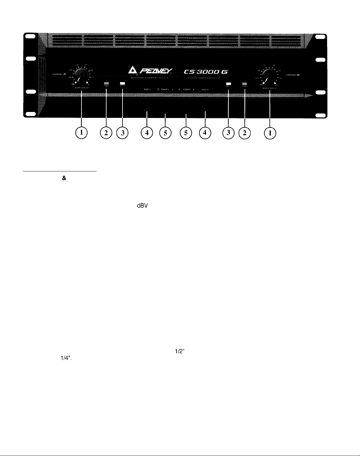
Front Panel:
FRONT PANEL FEATURES
CHANNELS A 81 B
INPUT SENSITIVITY (1)
The maximum input gain (minimum sensitivity rating) is achieved at the full clockwise setting, which yields the maximum
mixer/system headroom. A setting of less than full clockwise will yield lower system noise at the expense of mixer/system
headroom. Calibration indicates sensitivity in
dBV
necessary to attain the full available rated output power.
POWER LED (2)
Illuminates when AC power is being supplied to the amp, and the associated channel is operational. If either channel were
to experience fault conditions or to exceed the safe operating temperature limits, then that channel would shut down, and
the associated power LED would cease to illuminate, indicating such conditions exist. Also, whenever the Bridge mode is
selected, the power LED of channel B is defeated (off), just as if there were a fault condition on channel B. This provides
a positive indication that the CS 3000G is configured for Bridge mode.
DDT ACTIVE LED (3)
Illuminates when DDT Compression is taking place in that channel. With the ENABLE/DEFEAT switch in the DEFEAT
position, this LED indicates when clipping distortion is occurring in that channel.
CIRCUIT BREAKERS (4)
The CS 3000G uses circuit breakers in place of main fuses. These breakers are provided to limit the current
to the associated power transformer for each channel, and thereby offer protection from overheating and
A
A
When tripped, the button on the breaker will be outward nearly
length is about
period of time to allow it to cool down. REMEMBER, ALWAYS TURN THE POWER OFF BEFORE RESETTING THE
BREAKER. If the breaker trips instantly each time you attempt to reset it, the unit should be taken to a qualified service center
for repair.
POWER SWITCH (5)
Depress to the “I” position to turn on.
possible destruction due to fault conditions in the amplifier. The breaker trip current value has been carefully
chosen to allow continuous power output performance, yet still provide adequate protection for the power
transformer. Normally, these breakers should not trip unless there is a fault in the amp circuitry that draws
excessive mains current. However, abnormal conditions, such as a short circuit on either or both channels or
continuous operation at overload or clipping (especially into 2 ohm load) will cause the breaker to trip. If this
occurs, turn the power switch off, then simply reset the breaker and correct the cause of the overload.
l/2”
and can be reset by pushing inward. A normal reset button
l/4”.
If this “thermal” type breaker does trip, simply pushing the button back in will reset it, after waiting a brief
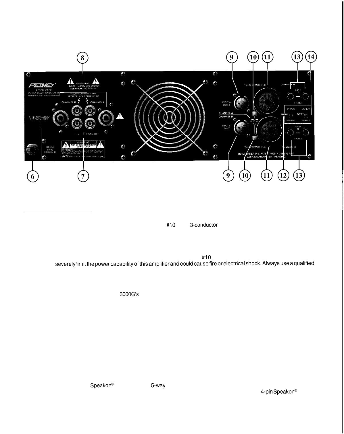
Back Panel:
BACK PANEL FEATURES
MAINS POWER SOURCE (6) 120 V products only
The CS 3000G is fitted with a single heavy-duty #lO AWG
a large ground pin. It should be connected to an independent mains circuit capable of supporting at least 30
A
GROUND LIFT SWITCH (7)
This switch is used to disconnect the CS
ground is the chassis itself, which is electrically grounded through the rack mounting screws to the external rack system and
through the mains line cord via the large ground pin to the mains ground. It is often advantageous to “lift” the signal ground
from chassis ground to eliminate a “ground loop” which has caused unwanted ground current in the signal cables between
the external preamp and this power amplifier. Such conditions can create excessive hum levels in the power amplifier output
and render the system useless in low level applications. In this case, “lifting” the ground should solve this hum problem.
Ground lift is selected when the switch is in the right or “LIFT” position. If lifting the ground does not eliminate a particular
hum problem, then we recommend you defeat the ground lift feature.
Note: Using this ground lift feature still leaves the chassis itself grounded electrically through the mains line cord. Having
the chassis grounded avoids any possibility of an electrical shock or a fire hazard. This ground lift feature should never be
confused with the practice of “floating” the large ground pin at the AC mains receptacle to eliminate a ground loop. Floating
the ground pin on any electrical equipment is just asking for trouble!!!
amps continuously or greater. This is particularly critical for sustained high power operation. If the socket used
does not have a ground pin, a suitable ground lift adaptor should be used and the third wire grounded properly.
Never break off the ground pin on the CS 3000G power amplifier. The use of extension cords should be avoided,
but if necessary, always use a three-wire type with at least a
severelylimitthepowercapabilityofthisamplifierandcouldcausefireorelectricalshock.Alwaysuseaqualified
electrician to install any necessary electrical equipment. To prevent the risk of shock or fire hazard, always be
sure that the amp is properly grounded.
3000G’s
“signal ground” (both input and output) from the “chassis ground.” Chassis
3-conductor
#lO
AWG wire size. The use of lighter wire will
line cord and a 30 amp T/P AC plug with
SPEAKER OUTPUTS (8)
Each channel
A
outputs are in parallel, hence the speaker connection cables can be terminated with
banana plugs, or stripped wires for use in the binding post terminals. Care must be exercised to assure correct
speaker phasing.
SpeakonO
connector and
5way
binding post speaker output terminals are provided. All these
4-pin Speakona
5
plugs,
Regardless of what connections are used, the typical parallel speaker load should always be limited to 2 ohms per channel
or 4 ohms Bridge mode for any application. Operation at loads of 4 ohms per channel or 8 ohms Bridge mode is more
desirable for sustained operation applications due to the fact that the amplifier will run much cooler at this load. Operation
above 4 ohms per channel, and even open circuit conditions can always be considered safe; however, any sustained
operation at loads below 2 ohms could result in temporary channel shut down due to the thermal limits and/or the amp fault
circuits.
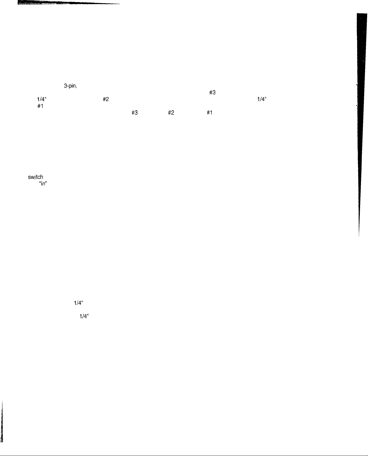
LOW-Z INPUT (9)
A conventional
3-pin,
female XLR input jack is provided and may be used as the channel input. When the (PL-2) line balancing
transformer is not used, this XLR input becomes Quasi-Balanced with pin #3 as the positive input (connecting to the tip of
the
i/4”
input jacks above), pin #2 as the negative input (connecting to the floating sleeve of the
l/4”
input jacks above), and
pin #l going to the internal power amplifier ground. When the (PL-2) line balancing transformer is used, this XLR input
becomes fully Transformer-Balanced (Pin #3 positive, pin #2 negative, pin #l ground). (See the PL-2 SELECTOR SWITCH
section (next) for details on related settings.)
PL-2 SELECTOR SWITCH (10)
This switch is used in conjunction with the PL-2 transformer to allow the LOW-Z INPUT to function with or without a PL-2
module being inserted in the receptacle. The “out” position of this switch selects the Quasi-Balanced mode of operation for
the LOW-Z INPUT (XLR jack), and routes the input signal directly to the HI-Z INPUT jacks. In this position the HI-Z INPUT
jacks may be used as outputs after the LOW-Z INPUT to allow patching this signal to another input on this amp. Normally,
in this switch position, a (PL-2) transformer is not present (“out”) in the transformer receptacle; however, if one were “in” the
receptacle, the LOW-Z INPUT would still be Quasi-Balanced. It becomes fully Transformer-Balanced only when the “in”
sw,itch
position is selected. Notice this is a very effective means to “test” for the necessity of a line-balancing transformer.
The
“in”
position of the switch routes the signals from the XLR jack through the (PL-2) line-balancing transformer, thereby
selecting the Transformer-Balanced mode of operation for the LOW-Z INPUT. In this position the HI-Z INPUT jacks may be
used as outputs after the line balancing transformer to patch the signal to another input jack on this amplifier or other amps/
equipment.
If the “in” position is selected without a (PL-2) line-balancing transformer “in” the receptacle, the LOW-Z INPUT
will be rendered inoperable.
TRANSFORMER RECEPTACLE (11)
This receptacle only receives the optional (PL-2) line-balancing transformer. When conditions exist that demand the usage
of a Transformer-Balanced XLR Input for either or both channels, then the (PL-2) transformer must be put here, and the
selector switch must be in the “in” position.
MODE SWITCH (12)
This switch is used to select either Stereo or Bridge mode operation. When BRIDGE mode is selected, the channel B LED
power indicator will go out indicating Bridge mode has been selected. Accidental selection of this mode could damage
loudspeakers. Bridge mode will be covered in more detail later in this manual.
HIGH-Z INPUT JACKS (13)
Two parallel (bridged) input jacks are provided for each channel. This allows for one to be used as a conventional input, and
at the same time the other to be used as a “line out” (Y-cord) to connect to another input jack on this amplifier or other amps/
equipment. These
l/4”
jacks are not “chassis grounded” and when used will provide a Quasi-Balanced input capability due
to a unique “ground loop” elimination circuitry associated with the inputs. This feature will normally allow “hum free” operation
when relatively short
l/4”
cable patches are made between the various jacks on this amp and other jacks on various other
equipment that share the same rack with this amplifier, This Quasi-Balanced capability is automatic and cannot be removed
from the system’s circuitry.
DDT COMPRESSION SWITCH (14)
This switch is used to either ENABLE or DEFEAT the DDT compressor. The DDT function will be covered in more detail later
in this manual.
6
INSTALLATION AND CONNECTION
The Peavey CS 3000G commercial series power amplifier is designed for durability in commercial installations and the
quality of performance required in studio and home applications. The unit is a standard rack-mount configuration,
3-l/2”
high
and is cooled by automatic two-speed internal fans. All of the input and output connections are on the back panel. The front
panel contains LED indicators for power and DDT activation,
detented/calibrated
sensitivity controls, and a mains power
switch.
INDUSTRIAL AND COMMERCIAL INSTALLATIONS
For commercial and other installations, where sustained high power operation is required, the
in a standard
19”
rack. It is not necessary to leave rack space between each amplifier in the stack, since the fan pulls air in
CS
3000G should be mounted
from the rear and exhausts the hot air out of the front. However, an adequate COOL air supply must be provided for the
amplifier when rack-mounted. The internal fan must have a source of air that is not preheated by other equipment. The
amplifierwill start up in “Low Speed” fan operation, and will normallystayat low speed operation unless sustained high power
operating levels occur. Then as the amplifier’s “Heat Sinks” heat up, the automatic thermal sensing circuitry will cause high
speed operation to occur. Depending on signal conditions and amp loading, high speed fan operation may continue or it may
cycle continuously between high and low. This situation is quite normal.
If cooling is inadequate due to preheated air, or a reduction of airflow occurs due to blockage of the amplifier inlet/outlet ports,
or if the amplifier is severely overloaded or short circuited, then the amplifier thermal sensing system may cause temporary
shutdown of that particular channel. This is indicated by the channel power LED on the front panel ceasing to illuminate.
Depending on available cooling air, operation should be restored in that channel relatively quickly, and the power LED will
be illuminated. In any event, corrective action should be taken to determine the cause of the thermal shutdown. If the amplifier
is not severely overloaded or shorted, and air flow is normal in and out of the unit, then steps should be taken to provide a
cooler environment for all the amplifiers. As a general rule, the cooler electronic equipment is operated, the longer its useful
service life.
BRIDGE MODE
The bridge mode on stereo amplifiers is often misunderstood as to the actual operation and usage. In basic terms, when
a two-channel amplifier is operated in the Bridge mode, it is converted into a single-channel unit with a power rating equal
to the sum of both channel’s power ratings, and at a load rating of twice that of the single channel rating. In this case, the
CS
3000G is rated at 1500 W
RMS
per channel into 2 ohms. Thus, the Bridge rating is 3000 W
RMS
into 4 ohms (minimum
load). Bridge mode operation is accomplished by placing the mode switch in the “BRIDGE” position, connecting the load
between the RED binding posts of each channel, and using channel A as the input channel. All the channel B functions as
an input are defeated and they serve no purpose in Bridge mode.
A popular application for Bridge mode operation is to drive sound distribution systems in large public address applications.
In this mode, the CS 3000G power amplifier can actually drive 70 volt systems directly without using expensive matching
transformers. The real advantage of such an approach is primarily cost.
70 volt distribution systems are very common in applications where rather large numbers of relatively small loudspeakers
are used for background music and paging. Such systems require the use of 70 volt transformers at each loudspeaker.
Another common use for the Bridge mode is in subwoofer applications where very high power levels are required to
adequately reproduce the extreme low frequencies. Such enclosures usually contain 2 or 4 loudspeakers to handle the
power levels involved. For Bridge mode usage, the enclosure impedance must be 4 or 8 ohms; never below 4 ohms! Also
make sure that the enclosure can handle 3000 watts reliably
DDT COMPRESSION
Peavey’s patented DDT compression system enables the sound man to maximize the performance of the amplifier/speaker
combination by preventing the power amp from running out of headroom (clipping). This compression system is activated
by a very unique circuit that senses signal conditions that might overload the amplifier and activates compression (reduces
the amp gain) when clipping is imminent. Threshold of compression, then, is clipping itself and no specific threshold control
is used. This technique effectively utilizes every precious watt available for the power amplifier to reproduce the signal while
at the same time minimizes clipping and distortion, and thus significantly reduces the potential of loudspeaker degradation
and damage. The DDT system is an automatic, hands-off approach to the problem of power amplifier clipping. Since the
CS
3000G power amplifier uses circuit breakers for the over-current protection, the DDT compression system plays even
a more important roll in continuous performance by preventing each channel from clipping and overloading. Continuous
operation at clipping can cause the circuit breaker to trip, but with the DDT activated, this problem is minimized. For this
reason you should always have the DDT compression system enabled.
7
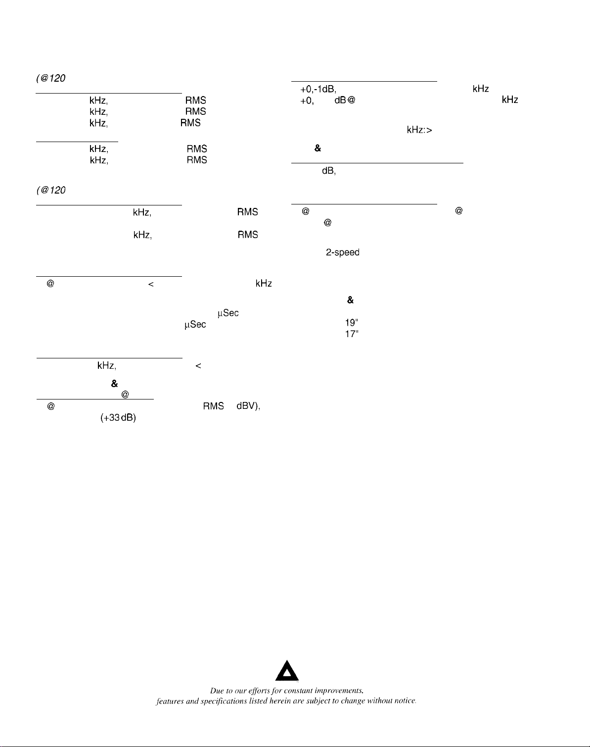
SPECIFICATIONS
Output Power: (typical value)
(@ 720
VAC, 60 Hz)
Stereo mode, both channels driven
2 ohms, 1
4 ohms, 1
8 ohms, 1
kHz,
1% THD: 1500 W
kHz,
1% THD: 1000 W
kHz,
1% THD: 600 W
RMS
per channel
RMS
per channel
RMS
per channel
Bridae mode, mono
4 ohms, 1
8 ohms, 1
Rated Output Power:
(63 120
kHz,
1% THD: 3000 W
kHz,
1% THD: 2000 W
VAC, 60 Hz)
RMS
RMS
Stereo mode. both channels driven
4 ohms, 20 Hz to 20
kHz,
0.04% THD: 900 W
per channel
8 ohms, 20 Hz to 20
kHz,
0.04% THD: 550 W
per channel
Power Bandwidth: (typical value)
Stereo mode. both channels driven
@
rated power, 4 ohms, < 0.1% THD: 10 Hz to 40
Slew Rate: (typical value)
Stereo mode, each channel: 40 volts per
Bridge mode, mono: 80 volts per
Total Harmonic Distortion: (typical)
uSec
FSec
Stereo mode. both channels driven
20 Hz to 20
Input Sensitivity & Impedance:
kHz,
4 ohm rated load: < 0.04%
Input attenuator set @ FCW
@
rated output power, 4 ohms: 1.5 V
20 k ohms
(+33 dB)
RMS
(0
RMS
RMS
dBV),
kHz
Frequency Response: (typical value)
Stereo mode. both channels driven
+0,-l
dB,
1 W RMS, 4 ohms: 10 Hz to 40
+O,
-0.3 dB @ rated output, 4 ohms: 20 Hz to 20
Damping Factor: (typical value)
Stereo mode, 8 ohms, 1
Hum & Noise:
kHz: >
300
kHz
kHz
Stereo mode, below rated power. 4 ohms
100
dB,
unweighted
Power Consumption:
Stereo mode, both channels driven
@
rated output power, 4 ohms: 25 A @ 120 V AC,
13A @ 230VAC
Cooling System:
Dual,
2-speed
DDT Compression System:
fans
Switchable with LED
Dimensions 81 Weight:
Height:
Width:
Depth:
5” (8.9 cm)
19”
(48.3 cm)
17”
(43.2 cm)
Weight: 35 Ibs. (15.9 kg)
Three-Rack Space, Class BG, Dual-Rail Design with
NSSER Topology (NSSER: Nonsaturating Series Single
Emitter Resistor).
Patent Pending.
8
3lWN3
1
‘l
lnOZ-ld
.
r’
-
dW ‘AMOd
1ndNl
Z-MO1
lndlil0
C
&
I mo
I-ld
NOYWdS
W 13NNWH3
1
I
1
I
dW
‘d3MOd
NOYWdS
a 13NNWH3
W 13NNWH3
 Loading...