


CC
CCTM Power Amplifier
Owner’s Manual
Intended to alert the user to the presence of uninsulated “dangerous voltage” within the product’s enclosure that  may be of sufficient magnitude to constitute a risk of electric shock to persons.
Intended to alert the user of the presence of important operating and maintenance (servicing) instructions in the lit- 

 erature accompanying the product.
CAUTION: Risk of electrical shock — DO NOT OPEN!
CAUTION:To reduce the risk of electric shock, do not remove cover. No user serviceable parts inside. Refer servicing to qualified service personnel.
WARNING:To prevent electrical shock or fire hazard, do not expose this appliance to rain or moisture. Before using this appliance, read the operating guide for further warnings.
Ce symbole est utilisé dans ce manuel pour indiquer à l’utilisateur la présence d’une tension dangereuse pouvant être 


 d’amplitude suffisante pour constituer un risque de choc électrique.
Ce symbole est utilisé dans ce manuel pour indiquer à l’utilisateur qu’il ou qu’elle trouvera d’importantes instructions 

 concernant l’utilisation et l’entretien de l’appareil dans le paragraphe signalé.
ATTENTION: Risques de choc électrique — NE PAS OUVRIR!
ATTENTION:Afin de réduire le risque de choc électrique, ne pas enlever le couvercle. Il ne se trouve à l’intérieur aucune pièce pouvant être reparée par l’utilisateur. Confiez I’entretien et la réparation de l’appareil à un réparateur agréé.
AVERTISSEMENT:Afin de prévenir les risques de décharge électrique ou de feu, n’exposez pas cet appareil à la pluie ou à l’humidité.Avant d’utiliser cet appareil, lisez attentivement les avertissements supplémentaires de ce manuel.
Dieses Symbol soll den Anwender vor unisolierten gefährlichen Spannungen innerhalb des Gehäuses warnen, die von  Ausreichender Stärke sind, um einen elektrischen Schlag verursachen zu können.
Dieses Symbol soll den Benutzer auf wichtige Instruktionen in der Bedienungsanleitung aufmerksam  machen, die Handhabung und Wartung des Produkts betreffen.
VORSICHT: Risiko — Elektrischer Schlag! Nicht öffnen!
VORSICHT: Um das Risiko eines elektrischen Schlages zu vermeiden, nicht die Abdeckung enfernen. Es befinden sich keine Teile darin, die vom Anwender repariert werden könnten. Reparaturen nur von qualifiziertem Fachpersonal durchführen lassen.
ACHTUNG: Um einen elektrischen Schlag oder Feuergefahr zu vermeiden, sollte dieses Gerät nicht dem Regen oder Feuchtigkeit ausgesetzt werden.Vor Inbetriebnahme unbedingt die Bedienungsanleitung lesen.

IMPORTANT SAFETY INSTRUCTIONS
WARNING: When using electrical products, basic cautions should always be followed, including the following:
1.Read these instructions.
2.Keep these instructions.
3.Heed all warnings.
4.Follow all instructions.
5.Do not use this apparatus near water.
6.Clean only with a dry cloth.
7.Do not block any of the ventilation openings. Install in accordance with manufacturer’s instructions.
8.Do not install near any heat sources such as radiators, heat registers, stoves or other apparatus (including amplifiers) that produce heat.
9.Do not defeat the safety purpose of the polarized or grounding-type plug. A polarized plug has two blades with one wider than the other. A grounding type plug has two blades and a third grounding plug. The wide blade or third prong is provided for your safety. If the provided plug does not fit into your outlet, consult an electrician for replacement of the obsolete outlet.
10.Protect the power cord from being walked on or pinched, particularly at plugs, convenience receptacles, and the point they exit from the apparatus.
11.Only use attachments/accessories provided by the manufacturer.
12.Use only with a cart, stand, tripod, bracket, or table specified by the manufacturer, or sold with the apparatus. When a
cart is used, use caution when moving the cart/apparatus combination to avoid injury from tip-over.
13.Unplug this apparatus during lightning storms or when unused for long periods of time.
14.Refer all servicing to qualified service personnel. Servicing is required when the apparatus has been damaged in any way, such as power-supply cord or plug is damaged, liquid has been spilled or objects have fallen into the apparatus, the apparatus has been exposed to rain or moisture, does not operate normally, or has been dropped.
15.Never break off the ground pin. Write for our free booklet “Shock Hazard and Grounding.” Connect only to a power supply of the type marked on the unit adjacent to the power supply cord.
16.If this product is to be mounted in an equipment rack, rear support should be provided.
17.Note for UK only: If the colors of the wires in the mains lead of this unit do not correspond with the terminals in your plug‚ proceed as follows:
a)The wire that is colored green and yellow must be connected to the terminal that is marked by the letter E‚ the earth symbol‚ colored green or colored green and yellow.
b)The wire that is colored blue must be connected to the terminal that is marked with the letter N or the color black.
c)The wire that is colored brown must be connected to the terminal that is marked with the letter L or the color red.
18.This electrical apparatus should not be exposed to dripping or splashing and care should be taken not to place objects containing liquids, such as vases, upon the apparatus.
19.Exposure to extremely high noise levels may cause a permanent hearing loss. Individuals vary considerably in susceptibility to noise-induced hearing loss, but nearly everyone will lose some hearing if exposed to sufficiently intense noise for a sufficient time. The U.S. Government’s Occupational Safety and Health Administration (OSHA) has specified the following permissible noise level exposures:
Duration Per Day In Hours |
Sound Level dBA, Slow Response |
8 |
90 |
6 |
92 |
4 |
95 |
3 |
97 |
2 |
100 |
1 1⁄2 |
102 |
1 |
105 |
1⁄2 |
110 |
1⁄4 or less |
115 |
According to OSHA, any exposure in excess of the above permissible limits could result in some hearing loss. Ear plugs or protectors to the ear canals or over the ears must be worn when operating this amplification system in order to prevent a permanent hearing loss, if exposure is in excess of the limits as set forth above. To ensure against potentially dangerous exposure to high sound pressure levels, it is recommended that all persons exposed to equipment capable of producing high sound pressure levels such as this amplification system be protected by hearing protectors while this unit is in operation.
SAVE THESE INSTRUCTIONS!

WICHTIGE SICHERHEITSHINWEISE
ACHTUNG: Beim Einsatz von Elektrogeräten müssen u.a. grundlegende Vorsichtsmaßnahmen befolgt werden:
1.Lesen Sie sich diese Anweisungen durch.
2.Bewahren Sie diese Anweisungen auf.
3.Beachten Sie alle Warnungen.
4.Befolgen Sie alle Anweisungen.
5.Setzen Sie dieses Gerät nicht in der Nähe von Wasser ein.
6.Reinigen Sie es nur mit einem trockenen Tuch.
7.Blockieren Sie keine der Lüftungsöffnungen. Führen Sie die Installation gemäß den Anweisungen des Herstellers durch.
8.Installieren Sie das Gerät nicht neben Wärmequellen wie Heizungen, Heizgeräten, Öfen oder anderen Geräten (auch Verstärkern), die Wärme erzeugen.
9.Beeinträchtigen Sie nicht die Sicherheitswirkung des gepolten Steckers bzw. des Erdungssteckers. Ein gepolter Stecker weist zwei Stifte auf, von denen einer breiter ist als der andere. Ein Erdungsstecker weist zwei Stifte und einen dritten Erdungsstift auf. Der breite Stift bzw. der dritte Stift dient Ihrer Sicherheit. Sollte der beiliegende Stecker nicht in Ihre Steckdose passen, wenden Sie sich bitte an einen Elektriker, um die ungeeignete Steckdose austauschen zu lassen.
10.Schützen Sie das Netzkabel, sodass niemand darauf tritt oder es geknickt wird, insbesondere an Steckern oder Buchsen und ihren Austrittsstellen aus dem Gerät.
11.Verwenden Sie nur die vom Hersteller erhältlichen Zubehörgeräte oder Zubehörteile.
12.Verwenden Sie nur einen Wagen, Stativ, Dreifuß, Träger oder Tisch, der den Angaben des Herstellers entspricht oder zusammen
mit dem Gerät verkauft wurde. Wird ein Wagen verwendet, bewegen Sie den Wagen mit dem darauf befindlichen Gerät besonders vorsichtig, damit er nicht umkippt und möglicherweise jemand verletzt wird.
13.Trennen Sie das Gerät während eines Gewitters oder während längerer Zeiträume, in denen es nicht benutzt wird, von der Stromversorgung.
14.Lassen Sie sämtliche Wartungsarbeiten von qualifizierten Kundendiensttechnikern durchführen. Eine Wartung ist erforderlich, wenn das Gerät in irgendeiner Art beschädigt wurde, etwa wenn das Netzkabel oder der Netzstecker beschädigt wurden, Flüssigkeit oder Gegenstände in das Gerät gelangt sind, das Gerät Regen oder Feuchtigkeit ausgesetzt wurde, nicht normal arbeitet oder heruntergefallen ist.
15.Der Erdungsstift darf nie entfernt werden. Auf Wunsch senden wir Ihnen gerne unsere kostenlose Broschüre „Shock Hazard and Grounding“ (Gefahr durch elektrischen Schlag und Erdung) zu. Schließen Sie nur an die Stromversorgung der Art an, die am Gerät neben dem Netzkabel angegeben ist.
16.Wenn dieses Produkt in ein Geräte-Rack eingebaut werden soll, muss eine Versorgung über die Rückseite eingerichtet werden.
17.Hinweis – Nur für Großbritannien: Sollte die Farbe der Drähte in der Netzleitung dieses Geräts nicht mit den Klemmen in Ihrem Stecker übereinstimmen, gehen Sie folgendermaßen vor:
a)Der grün-gelbe Draht muss an die mit E (Symbol für Erde) markierte bzw. grüne oder grün-gelbe Klemme angeschlossen werden.
b)Der blaue Draht muss an die mit N markierte bzw. schwarze Klemme angeschlossen werden.
c)Der braune Draht muss an die mit L markierte bzw. rote Klemme angeschlossen werden.
18.Dieses Gerät darf nicht ungeschützt Wassertropfen und Wasserspritzern ausgesetzt werden und es muss darauf geachtet werden, dass keine mit Flüssigkeiten gefüllte Gegenstände, wie z. B. Blumenvasen, auf dem Gerät abgestellt werden.
19.Belastung durch extrem hohe Lärmpegel kann zu dauerhaftem Gehörverlust führen. Die Anfälligkeit für durch Lärm bedingten Gehörverlust ist von Mensch zu Mensch verschieden, das Gehör wird jedoch bei jedem in gewissem Maße geschädigt, der über einen bestimmten Zeitraum ausreichend starkem Lärm ausgesetzt ist. Die US-Arbeitsschutzbehörde (Occupational and Health Administration, OSHA) hat die folgenden zulässigen Pegel für Lärmbelastung festgelegt:
Dauer pro Tag in Stunden |
Geräuschpegel dBA, langsame Reaktion |
8 |
90 |
6 |
92 |
4 |
95 |
3 |
97 |
2 |
100 |
1 1⁄2 |
102 |
1 |
105 |
1⁄2 |
110 |
1⁄4 oder weniger |
115 |
Laut OSHA kann jede Belastung über den obenstehenden zulässigen Grenzwerten zu einem gewissen Gehörverlust führen. Sollte die Belastung die obenstehenden Grenzwerte übersteigen, müssen beim Betrieb dieses Verstärkungssystems Ohrenstopfen oder
Schutzvorrichtungen im Gehörgang oder über den Ohren getragen werden, um einen dauerhaften Gehörverlust zu verhindern. Um sich vor einer möglicherweise gefährlichen Belastung durch hohe Schalldruckpegel zu schützen, wird allen Personen empfohlen, die mit Geräten arbeiten, die wie dieses Verstärkungssystem hohe Schalldruckpegel erzeugen können, beim Betrieb dieses Geräts einen Gehörschutz zu tragen.
BEWAHREN SIE DIESE SICHERHEITSHINWEISE AUF!

INSTRUCTIONS IMPORTANTES DE SECURITE
ATTENTION: L’utilisation de tout appareil électrique doit être soumise aux precautions d’usage incluant:
1.Lire ces instructions.
2.Gardez ce manuel pour de futures références.
3.Prétez attention aux messages de précautions de ce manuel.
4.Suivez ces instructions.
5.N’utilisez pas cette unité proche de plans d’eau.
6.N’utilisez qu’un tissu sec pour le nettoyage de votre unité.
7.N’obstruez pas les systèmes de refroidissement de votre unité et installez votre unité en fonction des instructions de ce manuel.
8.Ne positionnez pas votre unité à proximité de toute source de chaleur.
9.Connectez toujours votre unité sur une alimentation munie de prise de terre utilisant le cordon d’alimentation fourni.
10.Protégez les connecteurs de votre unité et positionnez les cablages pour éviter toutes déconnexions accidentelles.
11.N’utilisez que des fixations approuvées par le fabriquant.
12.Lors de l’utilsation sur pied ou pole de support, assurez dans le cas de déplacement de l’ensemble enceinte/
support de prévenir tout basculement intempestif de celui-ci.
13.Il est conseillé de déconnecter du secteur votre unité en cas d’orage ou de durée prolongée sans utilisation.
14.Seul un technicien agréé par le fabriquant est à même de réparer/contrôler votre unité. Celle-ci doit être contrôlée si elle a subit des dommages de manipulation, d’utilisation ou de stockage (humidité,…).
15.Ne déconnectez jamais la prise de terre de votre unité.
16.Si votre unité est destinée a etre montée en rack, des supports arriere doivent etre utilises.
17.Note pour les Royaumes-Unis: Si les couleurs de connecteurs du cable d’alimentation ne correspond pas au guide de la prise secteur, procédez comme suit:
a)Le connecteur vert et jaune doit être connectrer au terminal noté E, indiquant la prise de terre ou correspondant aux couleurs verte ou verte et jaune du guide.
b)Le connecteur Bleu doit être connectrer au terminal noté N, correspondnat à la couleur noire du guide.
c)Le connecteur marron doit être connectrer au terminal noté L, correspondant à la couleur rouge du guide.
18.Cet équipement électrique ne doit en aucun cas être en contact avec un quelconque liquide et aucun objet contenant un liquide, vase ou autre ne devrait être posé sur celui-ci.
19.Une exposition à de hauts niveaux sonores peut conduire à des dommages de l’écoute irréversibles. La susceptibilité au bruit varie considérablement d’un individu à l’autre, mais une large majorité de la population expériencera une perte de l’écoute après une exposition à une forte puissance sonore pour une durée prolongée. L’organisme de la santé américaine (OSHA) a produit le guide ci-dessous en rapport à la perte occasionnée:
Durée par Jour (heures) |
Niveau sonore moyen (dBA) |
8 |
90 |
6 |
92 |
4 |
95 |
3 |
97 |
2 |
100 |
1 1⁄2 |
102 |
1 |
105 |
1⁄2 |
110 |
1⁄4 ou inférieur |
115 |
D’après les études menées par le OSHA, toute exposition au delà des limites décrites ce-dessus entrainera des pertes de l’écoute chez la plupart des sujets. Le port de système de protection (casque, oreilette de filtrage,…) doit être observé lors de l’opération cette unité ou des dommages irréversibles peuvent être occasionnés. Le port de ces systèmes doit être observé par toutes personnes susceptibles d’être exposées à des conditions au delà des limites décrites ci-dessus.
GARDEZ CES INSTRUCTIONS!

INSTRUCCIONES IMPORTANTES PARA SU SEGURIDAD
CUIDADO: Cuando use productos electrónicos, debe tomar precauciones básicas, incluyendo las siguientes:
1.Lea estas instrucciones.
2.Guarde estas instrucciones.
3.Haga caso de todos los consejos.
4.Siga todas las instrucciones.
5.No usar este aparato cerca del agua.
6.Limpiar solamente con una tela seca.
7.No bloquear ninguna de las salidas de ventilación. Instalar de acuerdo a las instrucciones del fabricante.
8.No instalar cerca de ninguna fuente de calor como radiadores, estufas, hornos u otros aparatos (incluyendo amplificadores) que produzcan calor.
9.No retire la patilla protectora del enchufe polarizado o de tipo “a Tierra”. Un enchufe polarizado tiene dos puntas, una de ellas más ancha que la otra. Un enchufe de tipo “a Tierra” tiene dos puntas y una tercera “a Tierra”. La punta ancha (la tercera ) se proporciona para su seguridad. Si el enchufe proporcionado no encaja en su enchufe de red, consulte a un electricista para que reemplaze su enchufe obsoleto.
10.Proteja el cable de alimentación para que no sea pisado o pinchado, particularmente en los enchufes, huecos, y los puntos que salen del aparato.
11.Usar solamente añadidos/accesorios proporcionados por el fabricante.
12.Usar solamente un carro, pie, trípode, o soporte especificado por el fabricante, o vendido junto al aparato. Cuando se use
un carro, tenga cuidado al mover el conjunto carro/aparato para evitar que se dañe en un vuelco. No suspenda esta caja de ninguna manera.
13.Desenchufe este aparato durante tormentas o cuando no sea usado durante largos periodos de tiempo.
14.Para cualquier reparación, acuda a personal de servicio cualificado. Se requieren reparaciones cuando el aparato ha sido dañado de alguna manera, como cuando el cable de alimentación o el enchufe se han dañado, algún líquido ha sido derramado o algún objeto ha caído dentro del aparato, el aparato ha sido expuesto a la lluvia o la humedad, no funciona de manera normal, o ha sufrido una caída.
15.Nunca retire la patilla de Tierra.Escríbanos para obtener nuestro folleto gratuito “Shock Hazard and Grounding” (“Peligro de Electrocución y Toma a Tierra”). Conecte el aparato sólo a una fuente de alimentación del tipo marcado al lado del cable de alimentación.
16.Si este producto va a ser enracado con más equipo, use algún tipo de apoyo trasero.
17.Nota para el Reino Unido solamente: Si los colores de los cables en el enchufe principal de esta unidad no corresponden con los terminales en su enchufe‚ proceda de la siguiente manera:
a)El cable de color verde y azul debe ser conectado al terminal que está marcado con la letra E‚ el símbolo de Tierra (earth)‚ coloreado en verde o en verde y amarillo.
b)El cable coloreado en azul debe ser conectado al terminal que está marcado con la letra N o el color negro.
c)El cable coloreado en marrón debe ser conectado al terminal que está marcado con la letra L o el color rojo.
18.Este aparato eléctrico no debe ser sometido a ningún tipo de goteo o salpicadura y se debe tener cuidado para no poner objetos que contengan líquidos, como vasos, sobre el aparato.
19.La exposición a altos niveles de ruido puede causar una pérdida permanente en la audición. La susceptibilidad a la pérdida de audición provocada por el ruido varía según la persona, pero casi todo el mundo perderá algo de audición si se expone a un nivel de ruido suficientemante intenso durante un tiempo determinado. El Departamento para la Salud y para la Seguridad del Gobierno de los Estados Unidos (OSHA) ha especificado las siguientes exposiciones al ruido permisibles:
Duración por Día en Horas |
Nivel de Sonido dBA, Respuesta Lenta |
8 |
90 |
6 |
92 |
4 |
95 |
3 |
97 |
2 |
100 |
1 1⁄2 |
102 |
1 |
105 |
1⁄2 |
110 |
1⁄4 o menos |
115 |
De acuerdo al OSHA, cualquier exposición que exceda los límites arriba indicados puede producir algún tipo de pérdida en la audición. Protectores para los canales auditivos o tapones para los oídos deben ser usados cuando se opere con este sistema de sonido para prevenir una pérdida permanente en la audición, si la exposición excede los límites indicados más arriba. Para protegerse de una exposición a altos niveles de sonido potencialmente peligrosa, se recomienda que todas las personas expuestas a equipamiento capaz de producir altos niveles de presión sonora, tales como este sistema de amplificación, se encuentren protegidas por protectores auditivos mientras esta unidad esté operando.
GUARDE ESTAS INSTRUCCIONES!
important precautions
1Save the carton and packing materials! Should you ever need to ship the unit, use only the original factory packing.
For replacement packaging,call CrestAudio’s Customer Service Department directly.
2 Read all documentation before operating your equipment. Retain all documentation for future reference.
3Follow all instructions printed on unit chassis for proper operation.
4Never hold a power switch or circuit breaker in the "on" position, if it won’t stay there by itself!
5Do not use the unit if the electrical power cord is frayed or broken.
The power supply cords should be routed so that they are not likely to be walked on or pinched by items placed upon or against them.
6Always operate the unit with the AC ground wire connected to the electricalsystemground.Precautions should be taken so that the means of grounding of a piece of equipment is not defeated.
7Damage caused by connection to improper AC voltage is not covered by any warranty. Mains voltage must be correct and the same as that printed on the rear of the unit.
8Do not ground any hot (red) terminal.
Never connect a hot (red) output to groundortoanotherhot(red) output!
9Power down and disconnect units from mains voltage before making connections.
0Do not drive the inputs with a signal level greater than that required to enable equipment to reach full output.
¡Do not run the output of any amplifier channel back into another channel’s input.
Do not parallelor series-con- nect an amplifier output with any other amplifier output.
CrestAudio is not responsible for damage to loudspeakers for any reason.
ÔDo not connect the inputs or outputs of amplifiers to any other voltage source: such as a battery, mains source, or power supply, regardless of whether the amplifier is turned on or off.
£Connecting amplifier outputs to oscilloscopes or other test equipmentwhiletheamplifierisinbridged mono mode may damage both the amplifier and test equipment!
¢Do not spill water or other liquids into or on the unit,or operate the unit while standing in liquid.
ˆDo not block fan intake or exhaust ports.
Do not operate equipment on a surface or in an environment which may impede the normal flow of air around the unit: such as a bed, rug, weathersheet, carpet, or completely enclosed rack.
§If the unit is used in an extremely dusty or smoky environment: the unit should be periodically blown free of foreign matter.
¶Do not use the unit near stoves, heat registers, radiators, or other heat producing devices.
ƒThe power cord of equipment should be unplugged from the outlet when left unused for a long period of time.
Service Information
Do not remove the cover!
Removing the cover will expose you to potentially dangerous voltages.There are no user serviceable parts inside.
Equipment should be serviced by qualified service personnel when:
A.The power supply cord or the plug has been damaged.
B.The equipment has been exposed to rain.
C.The equipment does not appear to operate normally, or exhibits a marked change in performance.
D.The equipment has been dropped, or the enclosure damaged.
To obtain service:
contact your nearest Crest Audio Service Center, Distributor, Dealer, or Crest Audio at 201.909.8700 USA or visit www.crestaudio.com for additional information.
email techserve@crestaudio.com
This symbol is used to alert the operator to follow important procedures and precautions detailed in documentation.
This symbol is used to warn operators that uninsulated “dangerous voltages” are present within the equipment enclosure that may pose a risk of electric shock.
 WARNING
THE ON/OFF SWITCH IN THIS APPARATUS DOES NOT BREAK BOTH SIDES OF THE MAINS. HAZARDOUS ENERGY MAY BE PRESENT INSIDE THE ENCLOSURE WHEN THE POWER SWITCH IS IN THE OFF POSITION.

table of contents
1 how to use this manual p.2 introduction p.3
2 installationunpacking p.4 mounting connecting power cooling requirements operating precautions connecting inputs connecting outputs
3 featuresfront panel overview p.6 rear panel
4stereooperation modes p.9 parallel
bridged mono
5protection features p.10 automatic clip limiting
IGM™ impedance sensing thermal protection short circuit
DC voltage protection turn on/off protection AUTORAMP™ signal control
6safetyspeaker protectionp.12 user responsibility
7servicesupport and support p.13 contact us
aspecifications p.14
b wire gauge charts p.17
contents
appendices
ENGLISH p.1
DEUTSCH p.19
FRANÇAIS p.39
ESPAÑOL p.58
p.1

1how to use this manual
CCTM owner’s manual
conventions
terms
official CrestAudio features and
each indicator or control on the amplifier will appear as:terms
actions
specific actions or selections the user can execute will appear as:actions
tasks
are broken down into steps 1
2
3
warnings
Procedures notto attempt.
Issues or hazards to keep in mind when operating
the equipment.
a
indicators
What to look for on |
® |
the equipment display. |
Alerts, indicators, or prompts that may appear.
tips
Preferred methods. |
+ |
|
|
Helpful hints. |
|
Feature insights. |
|
see
see—refers to other sections of the manual containing supplementary information on the current topic or a related issue
note
note—supplementary feature information
p.2

welcome
Congratulations on your purchase of a Crest Audio CC™ Series power amplifier. Designed for years of reliable, flawless operation under rigorous use.The Crest CC Series amplifiers offer the sonic superiority and unsurpassed reliability for which Crest Audio is famous, while remaining surprisingly compact. Advanced technology and extensive protection circuitry allow operation with greater efficiency into difficult loads and power conditions.The ACL™ (Automatic Clip Limiting) circuit ensures troublefree operation into loads as low as 2 ohms.The Automatic Clip Limiting circuits protect drivers and ensure that sonic integrity is maintained,even in extreme overload conditions. Crest Audio’s high-efficiency designs use tunnel-cooled heat sinks and variable speed DC fans.This cooling topology maintains a lower overall operating temperature,resulting in longer output transistor life. Model CC 4000,CC 2800,and CC 1800 power amplifiers use CrestAudio’s innovative“Power Density” circuitry and packaging.
introduction 1
For your safety, |
a |
read the important |
|
precautions section, |
|
as well as input,output,and power connection sections.
p.3
2installation
unpacking
Upon unpacking, inspect the amplifier. If you find any damage, notify your supplier immediately. Only the consignee may institute a claim with the carrier for damage incurred during shipping. Be sure to save the carton and all packing materials. Should you ever need to ship the unit back to CrestAudio,one of its offices,service centers, or the supplier,use only the original factory packing.If the shipping carton is unavailable, contact Crest to obtain a replacement.
CCTM owner’s manual
For replacement |
+ |
|
|
packaging, call Crest |
|
Audio’s |
|
Customer Service |
|
Department directly. |
|
see—service and support
mounting
CC Series amplifiers will mount in standard 19" racks. Rear mounting ears are also provided for additional support,which is recommended in non-permanent installations like mobile or touring sound systems. Because of the cables and connectors on the rear panel,a right angle or offset screwdriver or hex key will make it easier to fasten the rear mounting ears to the rails.
connecting power
CC Series amplifier power requirements are rated at 1/8th power (typical music conditions) and 1/3rd power (extreme music conditions).The maximum power current draw rating is limited only by the front panel circuit breaker.Consult the specifications in theAppendices section for figures on the current that each amplifier will demand.Make sure the mains voltage is correct and is the same as that printed on the rear of the amplifier.Damage caused by connecting the amplifier to improperAC voltage is not covered by any warranty.Unless otherwise specified when ordered, Crest amplifiers shipped to customers are configured as follows:
Option 1 NorthAmerica |
120VAC / 60 Hz |
Option 2 Europe,Asia |
230VAC / 50 Hz |
Option 3 Australia |
240VAC / 50 Hz |
Option 4 SouthAmerica |
120VAC / 60 Hz or 240VAC / 50 Hz |
Always turn off and disconnect the amplifier from mains voltage before making audio connections. Also,as an extra precaution, have the attenuators turned down during power-up.
a
p.4

installation 2
cooling requirements
The CC™ Series amplifiers use a forced-air cooling system to maintain a low, even operating temperature. Air is drawn into the amplifier by fan(s) on the rear panel, courses through the cooling fins of the tunnel-configured channel heat sink(s),and then exhausts through the front panel grille. If a heat sink gets too hot, its sensing circuit will open the output relay,disconnecting the load from that particular channel.The CC 1800 utilizes one common heat sink and a single fan,but retains the separate circuitry. It is important to have an adequate air supply at the back of the amplifier and enough space around the front of the amplifier to allow the cooling air to escape. If the amp is rack mounted,do not use doors or covers on the front of the rack;the exhaust air must flow without resistance.If you are using racks with closed backs,use fans on the rear rack panel to pressurize the rack and ensure an ample air supply.
Make certain that there |
a |
|
|
is enough space around |
|
the front and rear of the |
|
amplifier to allow the |
|
heated air to escape. |
|
suggestion: In racks |
+ |
with closed backs allow at least one standard-rack-space opening for every four amps.
operating precautions
Make sure the mains voltage is correct and is the same as that printed on the rear of the amplifier. Damage caused by connecting the amplifier to improper AC voltage is not covered by any warranty.See the Connecting Power section for more information on voltage requirements.
Although the CC Series amplifiers haveAUTORAMP™ circuitry,which raises the signal level gradually after the output relay closes, it is always a good idea to have the gain controls turned down during power-up to prevent speaker damage if there is a high signal level at the inputs.Whether you buy or make them,use good-quality connections, input cables and speaker cables, along with good soldering technique, to ensure trouble-free operation.Most intermittent problems are caused by faulty cables.
Consult the Wire Gauge Charts to determine proper gauges for different load impedances and cable lengths.Remember that cable resistance robs amplifier power in two ways:power lost directly to resistance (I2R loss),and by increasing the impedance of the load presented to the amplifier,thereby decreasing the power demanded of the amplifier.Also make sure the mode switch is correctly set for the desired application. See Sections on Stereo,Parallel and Bridged Mono Operation for more information.
connecting inputs
Input connections are made via the 3-pin XLR (pin 2+) or 6.3 mm plug “Combi” connectors on the rear panel of the amplifier.The inputs are actively balanced.The input overload point is high enough to accept the maximum output level of virtually any signal source.
connecting outputs
All models have two output (speaker) connections per channel. Cables can be connected with banana plugs, spade lugs, or bare wire to the five-way binding posts. The preferred method is connection via the Speakon connectors.
a
Always turn off and disconnect the amplifier from mains voltage before making audio connections.Also, as an extra precaution, turn the attenuators down during power-up.
p.5
3 features overview
CCTM owner’s manual
2
|
-6 |
-10 |
-3 |
CC1800
PROFESSIONAL |
-15 |
|
|
|
|
1800 WATT |
-30 |
-1 |
POWER AMPLIFIER |
|
|
|
|
|
|
-80 ch A |
0dB |
2
|
-6 |
-10 |
-3 |
CC2800
PROFESSIONAL |
-15 |
|
|
|
|
2800 WATT |
-30 |
-1 |
POWER AMPLIFIER |
|
|
|
|
|
|
-80 ch A |
0dB |
2
|
-6 |
-10 |
-3 |
CC4000
PROFESSIONAL |
-15 |
|
|
|
|
4000 WATT |
-30 |
-1 |
POWER AMPLIFIER |
|
|
|
|
|
|
-80 ch A |
0dB |
|
3456 1 |
||
|
|
-6 |
|
ACL |
-10 |
|
-3 |
|
|
ON |
|
|
|
|
|
SIGNAL |
-15 |
|
|
|
|
|
|
|
|
|
-1 |
TEMP |
-30 |
|
POWER |
|
|
|
|
ACTIVE |
-80 |
ch B |
0dB |
|
3456 1 |
||
|
|
-6 |
|
ACL |
-10 |
|
-3 |
|
|
ON |
|
|
|
|
|
SIGNAL |
-15 |
|
|
|
|
|
|
|
|
|
-1 |
TEMP |
-30 |
|
POWER |
|
|
|
|
ACTIVE |
-80 |
ch B |
0dB |
|
3456 1 |
||
|
|
-6 |
|
ACL |
-10 |
|
-3 |
|
|
ON |
|
|
|
|
|
SIGNAL |
-15 |
|
|
|
|
|
|
|
|
|
-1 |
TEMP |
-30 |
|
POWER |
|
|
|
|
ACTIVE |
-80 |
ch B |
0dB |
p.6

features overview 3
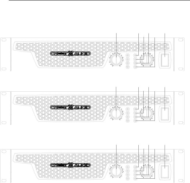
front panel
switches and controls
1AC Power Switch/Circuit Breaker
The CC Series amplifiers have a combinationAC switch/circuit breaker on the front panel.If the switch shuts off during normal use,push it back to the ON position once.If it will not stay on,the amplifier needs servicing.
2InputAttenuators
Whenever possible,set the attenuators fully clockwise to maintain optimum system headroom.The input attenuator controls (one for channelA,one for channel B) located at the front panel adjust gain for their respective amplifier channels in all modes.See the specifications at the end of this manual for standard voltage gain and input sensitivity information.
The power only breaks |
a |
|
one side of the AC mains. |
|
|
Hazardous energy may be |
|
|
present in the enclosure |
|
|
when the power switch is in |
|
|
the off position. |
|
|
When operating in the bridged |
a |
|
mode, both attenuators must be in the same position so the speaker load will be equally shared between the channels. See the section on Bridged Mono Operation for more information and precautions.
indicators
CC Series amplifiers feature four front panel LED indicators per channel:ACL™ (Automatic Clip Limiting),Signal,Temp,andActive.These LED indicators inform the user of each channel’s operating status and warn of possible abnormal conditions.
3ACL LED
A channel’sACL LED will light at the onset of clipping.If the LED’s are flashing quickly and intermittently,the channel is just at the clip threshold,while a steady,bright glow means the amp is clip limiting, or reducing gain to prevent severely clipped waveforms reaching
the loudspeakers.See theAutomatic Clip Limiting section for more information.During initial power up theACL LED will light indicating that theAUTORAMP™ gain reduction circuitry is activated.This will prevent sudden signal bursts when the speaker relays are closed.
4Signal LED
This LED lights when its channel produces an output signal of about 4 volts RMS or more (0.1 volt or more at the input,with 0 dB attenuation and standard x40 voltage gain).It is useful in determining whether a signal is reaching and being amplified by the amplifier.
5Temp LED
The Temp LED lights to indicate that the channel’s output relay is open, disconnecting the speaker(s) due to an overheating condition. Once the channel temperature has returned to safe operating conditions the LED will turn off, the channel's output relay will close, and the speaker(s) will be reconnected.
6Active LED
The Active LED indicates that its channel’s output relay is closed and the channel is operational. It lights under normal operation and remains on even when the channel is in Automatic Clip Limiting or ACL gain reduction.These are protection features which leave the output relay closed.If theActive LED goes off,there is no signal at the output connectors.
p.7
3 features overview
CCTM owner’s manual
23
INPUT
WWW.CRESTAUDIO.COM
This info will be on sticker
A PRODUCT OF CREST AUDIO CORP. FAIR LAWN, NJ 120 VAC
60 Hz 1000 WATTS
1
MOUNT IN RACK ONLY - CLASS 2 WIRING OUTPUT INSTALLER SUR SUPPORT
DE MONTAGE SEULEMENT
MADE IN CHINA
UL Sticker
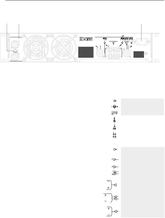
rear panel
1IEC power connector
Accepts a standard IEC terminated power cable
2Mode Select Switch
The rear panel Mode Select Switch determines whether the amplifier is in the stereo, parallel, or bridged mono mode. Do not operate the Mode Select Switch with the amplifier powered on.See the sections on Stereo and Bridged Mono Mode for more information.
3Gain Select Switch
The rear panel Gain Select Switch determines whether the amplifier has an overall gain of 40 (32 dB) or a gain of 20 (26 dB). The out position will select x40 while the in position will select x20.
rear panel legend
input connection
XLR connector polarity TRS connector polarity
bridged mono mode
parallel mode
stereo mode
output connection
Speakon® output channel A stereo/parallel
channel B stereo/parallel bridged mono
five- way
way binding post channel A stereo/parallel
bridged mono
channel B stereo/parallel
p.8

operation modes4
stereo
For stereo (dual channel) operation,turn the amplifier off and set the mode select switch to the stereo position. In this mode, both channels operate independently of each other, with their input attenuators controlling their respective levels.Thus, a signal at channel A’s input produces an amplified signal at channel A’s output, while a signal at channel B’s input produces an amplified signal at channel B’s output.
parallel
For parallel (dual-channel/single input) operation, turn the amplifier off and set the mode switch in the parallel position; both amplifier channels are then driven by the signal at channelA’s input.No jumper wires are needed. Output connections are the same as in the stereo mode. Channel A’s and channel B’s input connectors are strapped together to allow patching to another amplifier. Both input attenuators remain active, allowing you to set different levels for each channel. Power and other general performance specifications are the same as in the stereo mode.
bridged mono
Both amplifier channels can be bridged together to make a very powerful single-channel monaural amplifier. Use extreme caution when operating in the bridged mode; potentially lethal voltage may be present at the output terminals.To bridge the amplifier, turn the amplifier off and slide the rear panel amplifier mode select switch to the bridge position. Apply the signal to channelA’s input and connect the speakers across the hot outputs which are either the“+” binding posts of channelsA and B. Alternately connect across pins“1+POS” and“2+NEG” of the channelA Speakon® connector. As with parallel operation,both input connectors are strapped together to drive the input of another amplifier.
Unlike the stereo and parallel modes,in which one side of each output is at ground,in the bridged mode both sides are hot.ChannelA’s side is the same polarity as the input.The minimum nominal load impedance in the bridged mode is 4 ohms which is equivalent to driving both channels at 2 ohms. Driving bridged loads of less than 4 ohms will activate the ACL circuitry resulting in a loss of power,and may also cause a thermal overload.
When operating in the bridged mode, both attenuators must be in the same position so the speaker load will be equally shared between the channels.
a
p.9

5protection features
CCTM owner’s manual
CC Series amplifiers incorporate several circuits to protect both themselves and loudspeakers under virtually any situation. Crest Audio has attempted to make the amplifiers as foolproof as possible by making them immune to short and open circuits, mismatched loads, DC voltage, and overheating.If a channel goes into theAutomatic Clip Limiting orACL™ gain reduction mode,the speaker load remains connected, but clipping percentage or output power are instantly reduced. When a problem occurs that causes a channel to go into a protection mode, theTemp LED for that channel will glow. DC voltage on the output, excessive subsonic frequencies, or thermal overload will cause the channel’s output relay to disconnect the speaker load until the problem is corrected or the amplifier cools down.
automatic clip limiting (ACL)
Any time a channel is driven into hard, continuous clipping, the clip limiter circuit will automatically reduce the channel gain to a level just slightly into clipping,guarding the speakers against the damaging high power continuous square waves that may be produced. Situations that may activate the clip limiter include uncontrolled feedback, oscillation, or an improper equipment setting or malfunction upstream from the amplifier.Normal program transients will not trigger the clip limiter;only steady,excessive clipping will.TheACL LED will glow brightly and continuously when limiting occurs.
IGM™ impedance sensing
CC Series amplifiers feature innovative circuitry that allows safe operation into any load. When an amplifier sees a load that overstresses the output stage, the Instantaneous Gain Modulation (IGM) circuit adjusts the channel gain to a safe level.This method of output stage protection is far superior to conventional,brute force type limiting found on other amplifiers. The IGM circuit is sonically transparent in normal use and unobtrusive when activated.
thermal protection
The internal fans will keep the amplifier operating well within its intended temperature range under all normal conditions. If a channel’s heat sink temperature reaches 75°C, which may indicate an obstructed air supply,that channel will protect itself independently by disconnecting its load and shutting down until it has cooled. During this time, the channel’sTemp LED will glow, the Active LED will go out, the ACL LEDs will stay lit and the cooling fans will run at high speed.The CC 1800 utilizes one common heat sink and single fan, but retains the separate circuitry.
short circuit
If an output is shorted,the IGM and thermal circuits will automatically protect the amplifier.The IGM circuit senses the short circuit as an extremely stressful load condition and attenuates the signal,protecting the channel’s output transistors from over current stress.If the short circuit remains,the channel will eventually thermally protect itself by disconnecting the load.
DC voltage protection
If an amplifier channel detects DC voltage or subsonic frequencies at its output terminals,its output relay will immediately open to prevent loudspeaker damage.
p.10

protection features5
turn-on/turn-off protection
At power-up, the amplifier stays in the protect mode, with outputs disconnected, for approximately six seconds while the power supplies charge and stabilize.While the output relays are open,theACL LEDs light.When power is removed,the speaker loads immediately disconnect so that no thumps or pops are heard.
AUTORAMP™ signal control
Whenever a CC Series amplifier powers up or comes out of a protect mode,theAUTORAMP circuit activates. While the speakers are disconnected,theAUTORAMP circuit fully attenuates the signal. After the output relay closes,the signal slowly and gradually raises up to its set level. The AUTORAMP Signal Control circuit has some important advantages over conventional instant-on circuits:
1.If a signal is present during power-up (or when coming out of protect),the speakers are spared a sudden,potentially damaging burst of audio power.
2.Because the gain is reduced until after the output relay closes,no arcing occurs at the contacts,thereby extending their useful life.
p.11

6safety
CCTM owner’s manual
speaker protection
All loudspeakers have electrical,thermal and physical limits that must be observed to prevent damage or failure.Too much power,low frequencies applied to high frequency drivers,severely clipped waveforms,and DC voltage can all be fatal to cone and compression drivers.The Crest Audio CC Series amplifiers automatically protect speakers from DC voltages and subsonic signals.For more information,see the section on Protection Features.Midand high-frequency speakers,especially compression drivers,are highly susceptible to damage from overpowering, clipped waveforms,or frequencies below their rated passband.Be extremely careful that the low and mid bands of an electronic crossover are connected to the correct amplifiers and drivers and not accidentally connected to those for a higher frequency band.The amplifier’s clipping point is its maximum peak output power,and some of the higher power CrestAudio CC Series amplifiers can deliver more power than many speakers can safely handle. Be sure the peak power capability of the amplifier is not excessive for your speaker system.
To ensure that the speakers never receive excessive power and that the amplifier never clips, use a properly adjusted external limiter (or a compressor with a ratio of 10:1 or higher) to control power output.In systems with active electronic crossovers,use one for each frequency band.The clip limiter will automatically limit the duration of continuous square waveforms applied to the speakers.The amplifier will, however, allow normal musical transient bursts to pass. Some speaker systems are packaged with processors that have power limiting circuits and should not require additional external limiting.
Fuses may also be used to limit power to speaker drivers,although as current-limiting (rather than voltage-limiting devices) they are an imperfect solution. As the weakest links,fuses only limit once before needing replacement. Some poor quality fuses have a significant series resistance that could degrade the amplifier’s damping of the speaker’s motion and may even deteriorate the system’s sound quality.If you elect to use fuses,check with the speaker manufacturer to determine the proper current rating and time lag required.
Do not drive any low-frequency speaker enclosure with frequencies lower than its own tuned frequency.The reduced acoustical damping could cause a ported speaker to bottom out even at moderate power. Consult the speaker system specifications to determine its frequency limits.
amplifier maintenance and user responsibility
A CC Series amplifier requires no routine maintenance and should never need any internal adjustment during its lifetime.Your CC Series amplifier is very powerful and can be potentially dangerous to loudspeakers and humans alike. It is your responsibility to read the Important Precautions section in the front of this manual, and to make sure that the amplifier is installed, wired and operated properly. Many loudspeakers can be easily damaged or destroyed by overpowering, especially with the high power available from a bridged amplifier.Read the Speaker Protection section and always be aware of the speaker’s continuous and peak power capabilities.
p.12

service and support7
support
In the unlikely event that your amplifier develops a problem, it must be returned to an authorized distributor, service center, or shipped directly to our factory for service.
To obtain service, contact your nearest Crest Audio Service Center, Distributor, Dealer, or any of the worldwide Crest Audio offices. For those with Internet access,please visit the CrestAudio web site.
Because of the complexity |
+ |
|
|
of the design and the |
a |
risk of electrical shock, all repairs must be attempted only by qualified technical personnel. If the unit needs
to be shipped back to the factory, it must be sent in its original carton. If improperly packed, your amplifier may be damaged..
contact us
customer service
phone 866.812.7378 USA fax 601.486.1380 USA
email customerserve@crestaudio.com
technical support
phone 866.812.7378 USA fax 601.486.1380 USA
email techserve@crestaudio.com
web site www.crestaudio.com
CrestAudio Inc.
711A Street
Meridian,MS 39301 USA
For replacement packaging, call Crest Audio’s Customer Service.
+
p.13
a specifications
CC™ owner’s manual
CCTM Series |
1800 |
Rated Power Bridge 4 ohms |
1850 watts @ 1 kHz at <0.1% T.H.D. |
Rated Power (2 x 2 ohms) |
900 watts per channel @ 1 kHz <0.05% T.H.D. both channels driven |
Rated Power (2 x 4 ohms) |
700 watts per channel @ 1 kHz at <0.05% T.H.D. both channels driven |
Rated Power (2 x 8 ohms) |
450 watts per channel @ 1 kHz at <0.05% T.H.D. both channels driven |
Rated Power (1 x 2 ohms) |
950 watts @ 1 kHz at <0.05% T.H.D. |
Rated Power (1 x 4 ohms) |
775 watts @ 1 kHz at <0.05% T.H.D. |
Rated Power (1 x 8 ohms) |
475 watts @ 1 kHz at <0.05% T.H.D. |
Minimum Load Impedance |
2 ohms |
Maximum RMS Voltage Swing |
73 volts |
Frequency Response |
10 Hz - 100 kHz; +0, -3 dB at 1 watt |
Power Bandwidth |
10 Hz - 50 kHz; +0, -3 dB at rated 4 ohm power |
T.H.D. (2 x 2 ohms) |
<0.2% @ 700 watts per channel from 20 Hz to 20 kHz |
T.H.D. (2 x 4 ohms) |
<0.1% @ 600 watts per channel from 20 Hz to 20 kHz |
T.H.D. (2 x 8 ohms) |
<0.1% @ 425 watts per channel from 20 Hz to 20 kHz |
Input CMRR |
> - 75 dB @ 1 kHz |
Voltage Gain |
x40 (32 dB) x20 (26 dB) |
Crosstalk |
> -55 dB @ 1 kHz at rated power @ 8 ohms |
Hum and Noise |
> -106 dB, “A” weighted referenced to rated power @ 8 ohms |
Slew Rate |
> 35V/us |
Damping Factor (8 ohms) |
> 150:1 @ 20 Hz - 1 kHz at 8 ohms |
Phase Response |
+6 to - 12 degrees from 20 Hz to 20 kHz |
Input Sensitivity (x40) |
1.32 volts +/- 3% for 1 kHz, 4 ohm rated power, 1.06 volts +/- 3% for 1 kHz, 2 ohm rated power |
Input Impedance |
15 k ohms, balanced |
Current Draw @ 1/8 power |
1,000 watts @ 2 ohms, 685 watts @ 4 ohms, |
|
400 watts @ 8 ohms |
Current Draw @ 1/3 power |
2,340 watts @ 2 ohms, 1,650 watts @ 4 ohms, 1,000 watts @ 8 ohms |
Cooling |
One back panel temperature dependant variable speed 80 mm DC fan |
Controls |
2 front panel attenuators, rear panel Mode switches |
Indicator LEDs |
2 ACL™ (automatic clip limiting), 2 Signal presence, 2 Active status, 2 Temp |
Protection |
Thermal, DC, turn-on bursts, subsonic, incorrect loads |
Connectors |
Combi XLR & 6.3 mm phone input, Speakon and 5-way Binding Post speaker output, 15 amp |
|
IEC mains connector |
Construction |
16 ga. steel with cast front panel |
Dimensions |
88.9 mm x 482.6 mm x 377.8 mm + 31.8 mm for rear support ears and connectors |
|
(3.5" x 19" x 14.875" + 1.25") |
14.8 kg (32.6 lbs.)
15.9 kg (35 lbs.)
All power measurements made at 120 VAC, power transformer cold. 2 ohm power is time limited by magnetic circuit breaker.
p.14

|
|
specifications a |
|
|
2800 |
|
|
Rated Power Bridge 4 ohms |
2,800 watts @ 1 kHz at <0.1% T.H.D. |
||
Rated Power (2 x 2 ohms) |
1,400 watts per channel @ 1 kHz <0.05% T.H.D. both channels driven |
||
Rated Power (2 x 4 ohms) |
965 watts per channel @ 1 kHz at <0.05% T.H.D. both channels driven |
||
Rated Power (2 x 8 ohms) |
595 watts per channel @ 1 kHz at <0.05% T.H.D. both channels driven |
||
Rated Power (1 x 2 ohms) |
1,850 watts @ 1 kHz at <0.1% T.H.D. |
||
Rated Power (1 x 4 ohms) |
1,150 watts @ 1 kHz at <0.05% T.H.D. |
||
Rated Power (1 x 8 ohms) |
665 watts @ 1 kHz at <0.05% T.H.D. |
||
Minimum Load Impedance |
2 ohms |
|
|
Maximum RMS Voltage Swing |
82 volts |
|
|
Frequency Response |
10 Hz - 100 kHz; +0, -2.0 dB at 1 watt |
||
Power Bandwidth |
10 Hz - 35 kHz; +0, -3 dB at rated 4 ohm power |
||
T.H.D. (2 x 2 ohms) |
<0.15 @ 1,150 watts per channel from 20 Hz to 20 kHz |
||
T.H.D. (2 x 4 ohms) |
<0.1% @ 880 watts per channel from 20 Hz to 20 kHz |
||
T.H.D. (2 x 8 ohms) |
<0.1% @ 560 watts per channel from 20 Hz to 20 kHz |
||
Input CMRR |
> - 65 dB @ 1 kHz |
|
|
Voltage Gain |
x40 (32 dB) x20 (26 dB) |
||
Crosstalk |
> -65 dB @ 1 kHz at rated power @ 8 ohms |
||
Hum and Noise |
> -111 dB, “A” weighted referenced to rated power @ 8 ohms |
||
Slew Rate |
> 15V/us |
|
|
Damping Factor (8 ohms) |
> 500:1 @ 20 Hz - 1 kHz |
||
Phase Response |
+5 to - 15 degrees from 20 Hz to 20kHz |
||
Input Sensitivity (x40) |
1.7 volts +/- 3% for 1 kHz, 4 ohm rated power, 1.36 volts +/- 3% for 1 kHz, 2 ohm rated |
||
|
power |
|
|
Input Impedance |
15 k ohms, balanced |
|
|
Current Draw @ 1/8 power |
1,250 watts @ 2 ohms, |
880 watts @ 4 ohms, 570 @ 8 ohms |
|
Current Draw @ 1/3 power |
2,905 watts @ 2 ohms, |
2,220 watts @ 4 ohms, 1,355 watts @ 8 ohms |
|
Cooling |
Two back panel temperature dependant variable speed 80 mm DC fans |
||
Controls |
2 front panel attenuators, rear panel Mode switches |
||
Indicator LEDs |
2 ACL™ (automatic clip limiting), 2 Signal presence, 2 Active status, 2 Temp |
||
Protection |
Thermal, DC, turn-on bursts, subsonic, incorrect loads |
||
Connectors |
Combi XLR & 6.3 mm phone input, Speakon and 5-way Binding Post speaker output, 15 amp |
||
|
IEC mains connector |
|
|
Construction |
16 ga. steel with cast front panel |
||
Dimensions |
88.9 mm x 482.6 mm x 377.8 mm + 31.8 mm for rear support ears and connectors |
||
|
(3.5" x 19" x 14.875" + 1.25") |
||
Net Weight |
18.05 kg (39.8 lbs.) |
|
|
Gross Weight |
19.23 kg (42.4 lbs.) |
|
|
All power measurements made at 120 VAC, power transformer cold. 2 ohm power is time limited by magnetic circuit breaker.
p.15

a specifications |
|
CCTM owner’s manual |
|
|
|
|
|
CCTM Series |
|
|
|
|
|
4000 |
|
|
Rated Power Bridge 4 ohms |
4,000 watts @ 1 kHz at <0.1% T.H.D. |
|
|
Rated Power (2 x 2 ohms) |
2,000 watts per channel @ 1 kHz <0.1% T.H.D. both channels driven |
|
|
Rated Power (2 x 4 ohms) |
1,350 watts per channel @ 1 kHz at <0.05% T.H.D. both channels driven |
|
|
Rated Power (2 x 8 ohms) |
800 watts per channel @ 1 kHz at <0.05% T.H.D. both channels driven |
|
|
Rated Power (1 x 2 ohms) |
2,550 watts @ 1 kHz at <0.1% T.H.D. |
|
|
Rated Power (1 x 4 ohms) |
1,600 watts @ 1 kHz at <0.05% T.H.D. |
|
|
Rated Power (1 x 8 ohms) |
900 watts @ 1 kHz at <0.05% T.H.D. |
|
|
Minimum Load Impedance |
2 ohms |
|
|
Maximum RMS Voltage Swing |
93 volts |
|
|
Frequency Response |
10 Hz - 100 kHz; +0, -2 dB at 1 watt |
|
|
Power Bandwidth |
10 Hz - 35 kHz; +0, -3 dB at rated 4 ohm power |
|
|
T.H.D. (2 x 2 ohms) |
<0.2% @ 1,475 watts per channel from 20 Hz to 20 kHz |
|
|
T.H.D. (2 x 4 ohms) |
<0.1% @ 1,150 watts per channel from 20 Hz to 20 kHz |
|
|
T.H.D. (2 x 8 ohms) |
<0.1% @ 700 watts per channel from 20 Hz to 20 kHz |
|
|
Input CMRR |
> -65 dB @ 1 kHz |
|
|
Voltage Gain |
x40 (32 dB) x20 (26 dB) |
|
|
Crosstalk |
> -65 dB @ 1 kHz at rated power @ 8 ohms |
|
|
Hum and Noise |
> -112 dB, “A” weighted referenced to rated power @ 8 ohms |
|
|
Slew Rate |
> 15V/us |
|
|
Damping Factor (8 ohms) |
> 500:1 @ 20 Hz - 1 kHz |
|
|
Phase Response |
+5 to - 15 degrees from 20 Hz to 20 kHz |
|
|
Input Sensitivity (x40) |
1.88 volts +/- 3% for 1 kHz, 4 ohm rated power, 1.62 volts +/- 3% for 1 kHz, 2 ohm rated |
|
|
|
power |
|
|
Input Impedance |
15 k ohms, balanced |
|
|
Current Draw @ 1/8 power |
1,825 watts @ 2 ohms, |
1,185 watts @ 4 ohms, 720 @ 8 ohms |
|
Current Draw @ 1/3 power |
4,535 watts @ 2 ohms, |
2,975 watts @ 4 ohms, 1,835 watts @ 8 ohms |
|
Cooling |
Two back panel temperature dependant variable speed 80 mm DC fans |
|
|
Controls |
2 front panel attenuators, rear panel Mode switches |
|
|
Indicator LEDs |
2 ACL™ (automatic clip limiting), 2 Signal presence, 2 Active status, 2 Temp |
|
|
Protection |
Thermal, DC, turn-on bursts, subsonic, incorrect loads |
|
|
Connectors |
Combi XLR & 6.3 mm phone input, Speakon and 5-way Binding Post speaker output, 15 |
|
|
|
amp IEC mains connector |
|
|
Construction |
16 ga. steel with cast front panel and cast handles |
|
|
Dimensions |
88.9 mm x 482.6 mm x 377.8 mm + 31.8 mm for rear support ears and connectors |
|
|
|
(3.5" x 19" x 14.875" + 1.25") |
|
19.64 kg (43.3 lbs.)
20.8 kg.(45.8 lbs.)
All power measurements made at 120 VAC, power transformer cold. 2 ohm power is time limited by magnetic circuit breaker.
p.16

wire gauge b
stranded cable length
2meters
5meters
10meters
30meters
wire gauge |
|
|
power loss |
|
8Ω load |
4Ω load |
2 Ω load |
0.3mm2 |
2.9% |
5.6% |
10.8% |
0.5 |
1.74 |
3.4 |
6.7 |
0.75 |
1.16 |
2.3 |
4.5 |
1.5 |
0.58 |
1.16 |
2.3 |
2.5 |
0.35 |
0.70 |
1.39 |
4.0 |
0.22 |
0.44 |
0.87 |
0.5mm2 |
4.3% |
8.2% |
15.5% |
0.75 |
2.9 |
5.6 |
10.8 |
1.5 |
1.45 |
2.9 |
5.6 |
2.5 |
0.87 |
1.74 |
3.4 |
4 |
0.55 |
1.09 |
2.2 |
6 |
0.37 |
0.73 |
1.45 |
0.5mm2 |
8.24% |
5.5% |
28% |
0.75 |
5.6 |
10.8 |
19.9 |
1.5 |
2.9 |
5.6 |
10.8 |
2.5 |
1.74 |
2.9 |
6.7 |
4 |
1.09 |
1.74 |
4.3 |
6 |
0.73 |
1.09 |
2.9 |
0.75mm2 |
15.5% |
0.73% |
45% |
1.5 |
8.2 |
15.5 |
28 |
2.5 |
5.1 |
9.8 |
18.2 |
4 |
3.2 |
6.3 |
12.0 |
6 |
2.2 |
4.3 |
8.2 |
10 |
1.31 |
2.6 |
5.1 |
p.17

b wire gauge
CCTM owner’s manual
stranded cable length |
wire gauge |
|
|
power loss |
|
8Ω load |
4Ω load |
2 Ω load |
|
5feet |
|
|||
18AWG |
0.81% |
1.61% |
3.2% |
|
|
16 |
0.51 |
1.02 |
2.0 |
|
14 |
0.32 |
0.64 |
1.28 |
|
12 |
0.20 |
0.40 |
0.80 |
|
10 |
0.128 |
0.25 |
0.51 |
10feet |
18AWG |
1.61% |
3.2% |
6.2% |
|
16 |
1.02 |
2.0 |
4.0 |
|
14 |
0.64 |
1.28 |
2.5 |
|
12 |
0.40 |
0.80 |
1.60 |
|
10 |
0.25 |
0.51 |
1.01 |
40feet |
18AWG |
6.2% |
11.9% |
22% |
|
16 |
4.0 |
7.7 |
14.6 |
|
14 |
2.5 |
5.0 |
9.6 |
|
12 |
1.60 |
3.2 |
6.2 |
|
10 |
1.01 |
2.0 |
4.0 |
|
8 |
0.60 |
1.20 |
2.4 |
80feet |
18AWG |
11.9% |
22% |
37% |
|
16 |
7.7 |
14.6 |
26 |
|
14 |
5.0 |
9.6 |
17.8 |
|
12 |
3.2 |
6.2 |
11.8 |
|
10 |
2.0 |
4.0 |
7.7 |
|
8 |
1.20 |
2.4 |
4.7 |
p.18
DEUTSCH
Wichtige Sicherheitshinweise
1 Heben Sie den Karton und das Verpackungsmaterial bitte auf! Sollte es irgendwann einmal erforderlich sein, das Gerät zu versenden, verwenden Sie dazu ausschließlich die OriginalWerksverpackung
Für Ersatzverpackung wenden Sie sich bitte direkt an die Kundendienstabteilung von Crest Audio.
2 Lesen Sie sich die gesamte Dokumentation durch, bevor Sie Ihr Gerät in Betrieb nehmen. Bewahren Sie die gesamte Dokumentation auf, um später noch darin nachschlagen zu können.
3Um einen korrekten Betrieb zu garantieren, befolgen Sie alle Anweisungen, die auf dem Gerät aufgedruckt sind.
4Versuchen Sie nicht mit Gewalt, einen Netzoder Schutzschalter auf der Position ON zu halten, wenn er immer wieder von alleine herausspringt!
5Schalten Sie das Gerät nicht ein, wenn das Netzkabel ausgefranst oder beschädigt ist
Die Netzkabel müssen so verlegt werden, dass niemand darauf treten kann und dass sie nicht durch Gegenstände gequetscht werden, die darauf gestellt oder daran gelehnt werden.
6 Betreiben Sie das Gerät immer mit an die elektrische Systemerdung angeschlossenem WechselstromErdungskabel. Es müssen Vorsichtsmaßnahmen ergriffen werden, damit die Erdungsvorrichtung an einem Ausrüstungsteil nicht beeinträchtigt wird.
7 Schäden, die aufgrund des Anschlusses an eine ungeeignete Wechselspannung entstehen, werden nicht von der Garantie abgedeckt. Die Netzspannung muss korrekt sein und mit den Angaben auf der Rückseite des Geräts übereinstimmen.
8Erden Sie keine spannungsführenden (roten) Klemmen.
Schließen Sie nie einen spannungsführenden (roten) Ausgang an die Erde oder einen anderen spannungsführenden (roten) Ausgang an!
9 Schalten Sie die Geräte immer aus und trennen Sie sie von der Netzspannung, bevor Sie Anschlüsse durchführen.
0 Treiben Sie die Eingänge nicht mit einem Signalpegel über dem Pegel, der erforderlich ist, damit die Ausrüstung ihre volle Leistung erreicht.
¡Schließen Sie den Ausgang eines Verstärkerkanals nicht wieder an den Eingang eines anderen Kanals an.
Schließen Sie einen Verstärkerausgang nicht parallel oder in Reihe an einen anderen Verstärkerausgang an.
Crest Audio ist nicht verantwortlich für Schäden, die aus jedweden Gründen an Lautsprechern entstehen.
ÔSchließen Sie die Eingänge oder Ausgänge von Verstärkern nicht an andere Spannungsquellen an, wie Batterien, Stromanschlüsse oder Netzteile, ganz gleich ob der Verstärker einoder ausgeschaltet ist.
¶BetreibenSiedasGerätnichtneben Öfen, Heizungen, Heizgeräten oder anderen Geräten,dieWärme erzeugen.
ƒDie Netzkabel der Geräte müssen aus der Steckdose gezogen werden, wennsielängereZeitnichteingesetzt werden.
Kundendienstinformationen
Entfernen Sie nicht die Blende!
Wird die Blende entfernt, werden möglicherweise gefährliche Spannungen freigesetzt. Im Gerät befinden sich keine vom Anwender zu wartendenTeile.
Die Ausrüstung sollte in den folgenden Fällen von qualifizierten Kundendiensttechnikern gewartet werden:
A.Das Netzkabel oder der Stecker wurden beschädigt.
B.Die Ausrüstung war Regen ausgesetzt.
C.Die Ausrüstung arbeitet anscheinend nicht normal oder mit deutlich veränderter Leistung.
D.DieAusrüstung ist heruntergefallen oder das Gehäuse ist beschädigt.
£ Werden Verstärkerausgänge |
an |
|
|
||
Oszilloskope oder andere Testgeräte |
Hier erreichen Sie den Kundendienst: |
||||
angeschlossen, während sich |
der |
Wenden Sie sich bitte an Ihr Crest- |
|||
Verstärker im Bridged-Mono-Betrieb |
Audio-Kundendienstcenter, |
Ihren |
|||
befindet, könnensowohlVerstärkerals |
Vertrieb oder Händler, oder Crest Audio, |
||||
auchTestgeräte beschädigt werden! |
Tel. 201.909.8700 (USA) oder besuchen |
||||
|
|
|
|
Sie www.crestaudio.com für |
weitere |
|
|
|
|
Informationen. |
|
|
|
|
|
|
|
¢Verschütten Sie kein Wasser oder Flüssigkeiten in oder auf das Gerät, und betreiben Sie es nicht,wenn es auf nassem Boden steht.
ˆLüfteroder Abluftöffnungen dürfen nicht blockiert werden.
Betreiben Sie dieAusrüstung nicht
auf Flächen oder in Umgebungen, in denen der normale Luftstrom um das Gerät behindert ist, wie etwa Betten, Wolldecken, Abdeckplanen, Teppiche oder vollständig abgeschlossene Racks.
§ Wird das Gerät in einer extrem staubigen oder verrauchten Umgebung eingesetzt, muss es regelmäßig von Staub usw. gereinigt werden.
email techserve@crestaudio.com
Dieses Symbol weist den Bediener auf wichtige zu befolgende Vorgehensweisen und Sicherheitshinweise hin, die in der Dokumentation ausführlich behandelt werden.
Dieses Symbol warnt die Bediener vor nicht isolierten „gefährlichen  Spannungen“, die innerhalb des Gerätegehäuses vorliegen und die Gefahr des elektrischen Schlags bergen können.
 WARNUNG
DER AN/AUS SCHALTER IN DIESEM GERÄT UNTERBRICHT NICHT BEIDE SEITEN DES NETZES. AUCH WENN DER SCHALTER AUF "AUS" STEHT KANN IM INNERN DES GERÄTES IMMER NOCH GEFÄHRLICHE ELEKTRISCHE ENERGIEN VORHANDEN SEIN.
 Loading...