

Page 1
CA-A540B /CA-A800B
Cinema Power Amplifiers
™
™
Operating Guide
Operating Guide
¨
Page 2
Intended to alert the user to the presence of uninsulated Òdangerous voltageÓ within the productÕs
enclosure that may be of sufficient magnitude to constitute a risk of electric shock to persons.
Intended to alert the user of the presence of important operating and maintenance (servicing)
instructions in the literature accompanying the product.
CAUTION: Risk of electrical shock Ñ DO NOT OPEN!
CAUTION: To reduce the risk of electric shock, do not remove cover. No user serviceable parts inside. Refer
servicing to qualified service personnel.
WARNING: To prevent electrical shock or fire hazard, do not expose this appliance to rain or moisture. Before
using this appliance, read the operating guide for further warnings.
Este s’mbolo tiene el prop—sito, de alertar al usuario de la presencia de Ò(voltaje) peligrosoÓ sin aislamiento dentro de la caja del producto y que puede tener una magnitud suficiente como para constituir
riesgo de descarga elŽctrica.
Este s’mbolo tiene el prop—sito de alertar al usario de la presencia de instruccones importantes sobre la
operaci—n y mantenimiento en la informaci—n que viene con el producto.
PRECAUCION: Riesgo de descarga elŽctrica ÁNO ABRIR!
PRECAUCION: Para disminu’r el riesgo de descarga elŽctrica, no abra la cubierta. No hay piezas œtiles dentro.
Deje todo mantenimiento en manos del personal tŽcnico cualificado.
ADVERTENCIA: Para evitar descargas elŽctricas o peligro de incendio, no deje expuesto a la lluvia o humedad
este aparato Antes de usar este aparato, Iea m‡s advertencias en la gu’a de operaci—n.
Ce symbole est utilisŽ dans ce manuel pour indiquer ˆ lÕutilisateur la prŽsence dÕune tension dangereuse
pouvant •tre dÕamplitude suffisante pour constituer un risque de choc Žlectrique.
Ce symbole est utilisŽ dans ce manuel pour indiquer ˆ lÕutilisateur quÕil ou quÕelle trouvera dÕimportantes
instructions concernant lÕutilisation et lÕentretien de lÕappareil dans le paragraphe signalŽ.
ATTENTION: Risques de choc Žlectrique Ñ NE PAS OUVRIR!
ATTENTION: Afin de rŽduire le risque de choc Žlectrique, ne pas enlever le couvercle. Il ne se trouve ˆ lÕintŽrieur
aucune pi•ce pouvant •tre reparŽe par lÕutilisateur. Confiez IÕentretien et la rŽparation de lÕappareil ˆ un rŽparateur
Peavey agrŽŽ.
AVERTISSEMENT: Afin de prŽvenir les risques de dŽcharge Žlectrique ou de feu, nÕexposez pas cet appareil ˆ la
pluie ou ˆ lÕhumiditŽ. Avant dÕutiliser cet appareil, lisez attentivement les avertissements supplŽmentaires de ce
manuel.
Dieses Symbol soll den Anwender vor unisolierten gefŠhrlichen Spannungen innerhalb des GehŠuses
warnen, die von Ausreichender StŠrke sind, um einen elektrischen Schlag verursachen zu kšnnen.
Dieses Symbol soll den Benutzer auf wichtige Instruktionen in der Bedienungsanleitung aufmerksam
machen, die Handhabung und Wartung des Produkts betreffen.
VORSICHT: Risiko Ñ Elektrischer Schlag! Nicht šffnen!
VORSICHT: Um das Risiko eines elektrischen Schlages zu vermeiden, nicht die Abdeckung enfernen. Es befinden
sich keine Teile darin, die vom Anwender repariert werden kšnnten. Reparaturen nur von qualifiziertem
Fachpersonal durchfŸhren lassen.
ACHTUNG: Um einen elektrischen Schlag oder Feuergefahr zu vermeiden, sollte dieses GerŠt nicht dem Regen
oder Feuchtigkeit ausgesetzt werden. Vor Inbetriebnahme unbedingt die Bedienungsanleitung lesen.
2
Page 3

CA-A540Bªand CA-A800B
ª
Common Features
¥ SPSªcompression with LED indicators and defeat switch
¥ Slew Rate: 20 V/microsecond, stereo mode
¥ Frequency Response (each channel): 20 Hz to 20 kHz, ±0.2 dB, at rated power
¥ Total Harmonic Distortion: Less than 0.07%, at rated power
¥ Hum and Noise: 100 dB below rated power, unweighted
Congratulations! You are now the owner of a Peavey CinemAcousticsªamplifier designed especially
for the theater marketplace. The Peavey CinemAcoustics amplifiers, models CA-A540Bªand CAA800Bª, are the result of the latest developments in technology, allowing Peavey to provide you with
cost-effective amplifiers that do not sacrifice performance or reliability, while still continuing to meet
the demanding needs of todayÕs digital theater.
In the development of the CinemAcoustics CA-A540B and CA-A800B amplifiers, PeaveyÕs engineers
left no stone unturned. Right up front at the power source, CinemAcousticsÕ amplifiers utilize
massive power transformers, which are based on a new approach to power transformer design,
optimizing both cost and performance. On the power delivery side, these amplifiers utilize the latest
in semiconductor power device technology and implement a unique, two-speed fan-cooled heat sink
arrangement, insuring quality and ruggedness. The features and performance found in these
amplifiers place them in a class of their own Ñ the CinemAcoustics line!
Each amplifier is attractively packaged with rugged rack-mountable construction. The front panel of
each amplifier contains a rocker mains power switch, an LED power indicator, and dual LED SPS
activation indicators. The back panel of each amplifier has a resetable circuit breaker, an input level
control, a Euro input connector, and an output barrier strip. Additionally, the back panel contains
switches for stereo/bridge select and SPS defeat.
This operating guide is intended to serve both the CA-A540B and CA-A800B CinemAcoustics series
power amplifiers. Although each has different power ratings, the overall packaging and features are
similar.
ENGLISH
3
Page 4
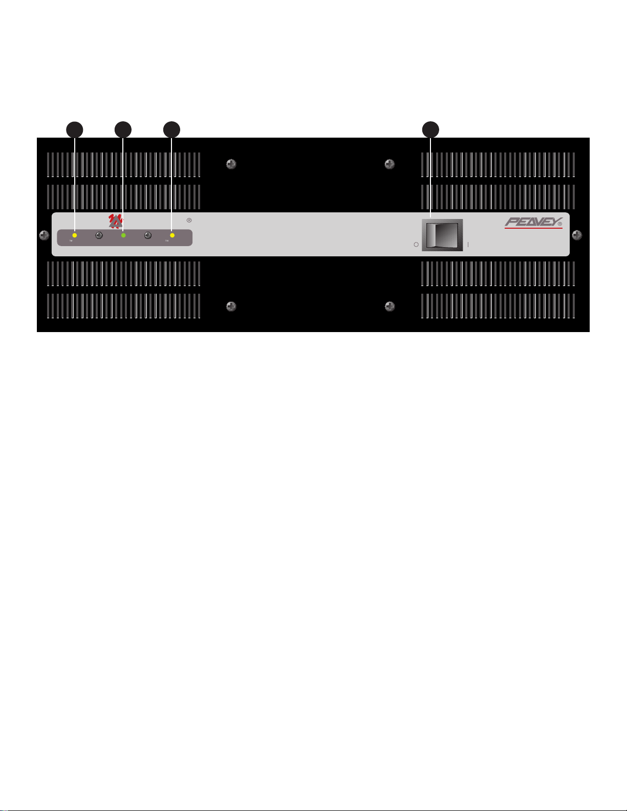
(1) SPS COMPRESSION ACTIVE LED
These indicators, one per channel, illuminate when SPS compression is taking place. This LED
becomes a CLIP indicator when the rear panel SPS ENABLE/DEFEAT switch is in the DEFEAT
position.
(2) POWER LED
This indicator illuminates when AC mains power is applied to the amplifier and both channels are
operational. The power LED will go dark if AC mains power is disconnected, if either channel
experiences a fault condition, or if the amplifier exceeds the safe operating temperature limits.
(3) MAINS POWER SWITCH
The mains power switch is a heavy-duty, rocker-type switch. Selecting the ÒOÓ position turns the
power amplifier off. Selecting the ÒIÓ position turns the power amplifier on.
FRONT PANEL CA-A800B
1
2 31
4
Cinem
SPS ACTIVE A SPS ACTIVE BPOWER ON
CINEMA POWER AMPLIFIER
POWER
coustics
CA - A800B
Page 5

(4) MAINS POWER SOURCE
All CinemAcoustics Series power amplifiers are fitted with a single, heavy-duty, three-conductor line
cord and a conventional, three-terminal AC plug with a ground pin for 120 V products. For 100 V
and 220 V products, the line cord is fitted with the appropriate power connector. The power plug
should be connected to an independent circuit capable of supporting at least 15 amps for 100 V and
120 V service, and 7.5 amps for 220 V service. This is particularly important for applications where
the amplifiers will be continuously operated at, or near, their maximum power rating. The use of
extension cords should be avoided, but when necessary, use a three-wire type with at least a 14
WG wire size.
Always allow a qualified electrician to install any new electrical service. The ground pin of the
power plug is provided for your safety and should not be defeated. To prevent the risk of shock
or fire hazard, always be sure that the amplifier is properly grounded.
NOTE: FOR UK ONLY
As the colors of the wires in the mains lead of this apparatus may not correspond with the colored
markings identifying the terminals in your plug, proceed as follows: (1) The wire which is colored
green and yellow must be connected to the terminal which is marked by the letter E, or by the earth
symbol, or colored green or green and yellow. (2) The wire which is colored blue must be connected
to the terminal which is marked with the letter N, or the color black. (3) The wire which is colored
brown must be connected to the terminal which is marked with the letter L or the color red.
(5) CIRCUIT BREAKER
The power circuit breaker serves to protect the amplifier. The trip current value has been
carefully chosen to allow continuous operation at the rated power while still offering adequate
protection. Under normal conditions, the breaker will not trip unless there is a fault condition that
draws excessive mains current. Please note, however, that abnormal conditions such as a short
circuit applied to an output or continuous operation at overload or clipping will also cause the
breaker to trip. If you suspect that the breaker has tripped because of abnormal conditions, be sure
to remedy the cause of the fault before resetting the breaker. When tripped, the breaker button
extends outward nearly 1/2", and can be reset by pushing inward after a brief wait to allow the
breaker to cool down. When not tripped, the breaker button extends outward about 1/4". If the
BACK PANEL CA-A800B
4
5
8
9
6
7
10
11
5
+ +
BA
OUTPUT
MONITOR
RESET
120 VAC
1500 WATTS
BUILT UNDER U.S. PATENT NO. 4,318,053
400W/8 OHMS 56.6V RMS PER CHANNEL
700W/4 OHMS 52.9V RMS PER CHANNEL
1000W/2 OHMS 44.7V RMS PER CHANNEL
INSTALLER SUR SUPPORT DE MONTAGE SEULEMENT
60 Hz
OUTPUT B OUTPUT A
+
+
2 OHM MINIMUM LOAD
CLASS 2 WIRING
MOUNT IN RACK ONLY.
Cinem
CINEMA POWER AMPLIFIER
dBV INPUT SENSITIVITY
+15
+12
+18
+9
+21
+6
+3
A DIVISION OF PEAVEY ELECTRONICS CORP
MERIDIAN, MS. MADE IN U.S.A.
INPUT B INPUT A
+
+
--
CA - A800B
coustics
dBV INPUT SENSITIVITY
+15
+12
+18
+21
SPS
+9
+6
+3
MODE
ENABLE
DEFEAT
TM
STEREO
BRIDGE
Page 6

breaker trips instantly each time you attempt to reset it, the unit should be taken to a qualified
service center for repair.
(6) OUTPUT MONITOR
This standard Quick-ConnectªRJ11 modular connector provides Channel A and B signals to
PeaveyÕs booth monitor products such as the CA-M400. Refer to the diagram above the connector
for proper polarity. (+ is equal to the channelÕs positive output.) The channels are indicated below the
connector.
(7) BARRIER STRIP SPEAKER OUTPUTS
The SPEAKER OUTPUTS for each channel are provided by means of a heavy-duty, four screw
barrier strip. The screw terminals marked Ò+Ó are the power amplifier outputs for each channel.
The remaining screw terminals are ground (chassis). The minimum recommended speaker load
impedance is 4 ohms per channel, or 8 ohms in BRIDGE mode. Operation into loads below the
recommended load impedance can result in temporary amplifier shutdown due to internal fault
sensing.
(8) SPS SWITCH
This switch is used to either ENABLE or DEFEAT the SPS safety compressor. Normally, the SPS
switch should be in the ENABLE position to minimize the possibility of a channel going into clipping
or overload. With SPS defeated, a severe overload could cause the unitÕs circuit breaker to trip.
(9) MODE SWITCH
This switch is used to select either STEREO or BRIDGE mode for the amplifier operation. Care
should be exercised whenever the BRIDGE mode is selected. Accidental selection of this mode
could cause damage to loudspeakers, particularly in BIAMPED systems. NOTE: Peavey does not
recommend the use of BRIDGE mode for normal theater applications.
(10) INPUT LEVEL
The INPUT controls are labeled in approximately 3 dB increments for ease of gain adjustment.
Maximum input gain is achieved at the full clockwise setting. When used with CinemAcoustics
signal processors, these controls should be left in the full clockwise position.
6
Page 7
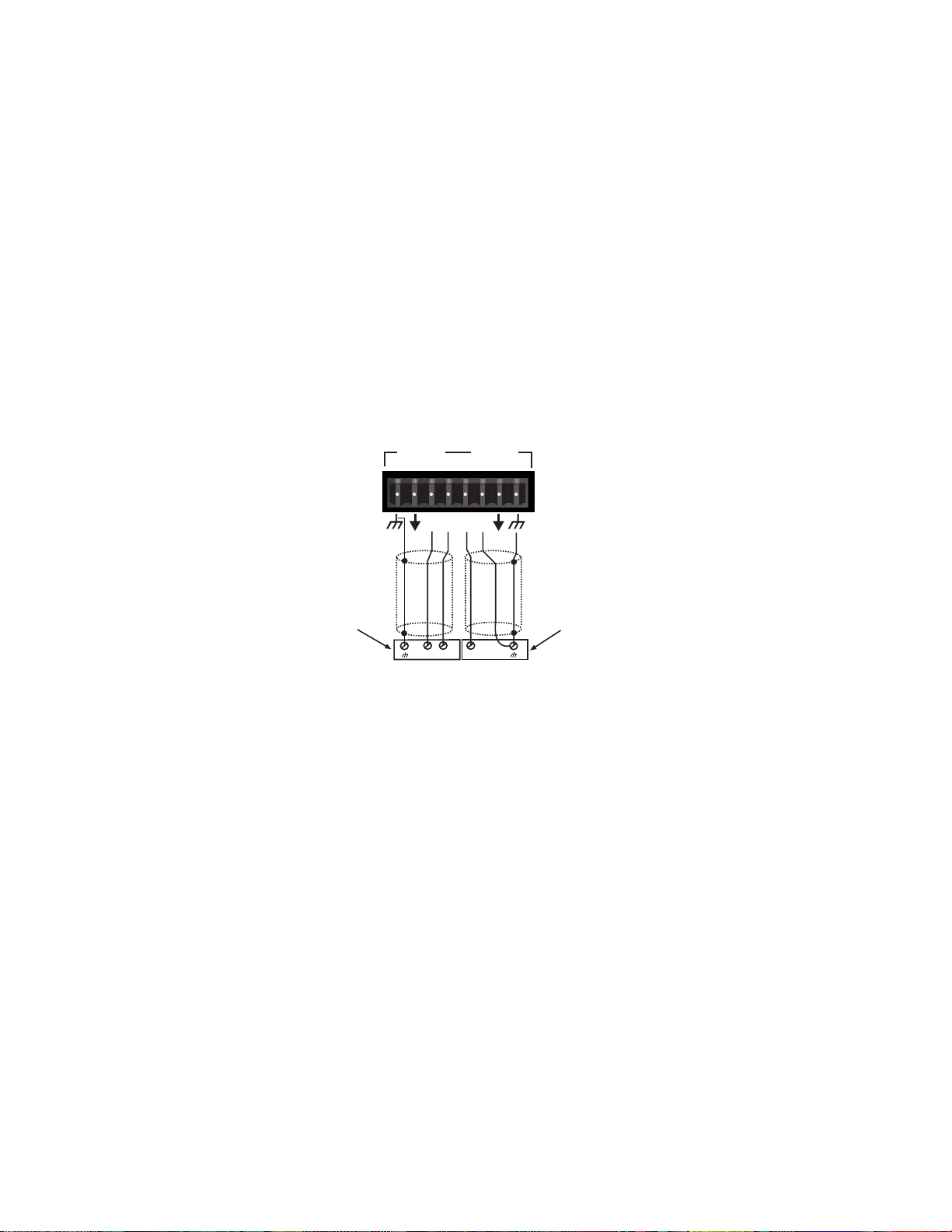
(11) EURO CONNECTOR INPUTS
The popular plugable Euro connector is provided for the inputs for each channel. These inputs
are balanced electronically, with the terminals marked Ò+Ó as the positive amplifier inputs, and the
terminals marked Ò-Ó as the negative amplifier inputs. The remaining terminals are ground (chassis).
If possible, always use two-conductor, shielded cables when interconnecting to the amplifier;
connecting the twisted pair to the respective Ò+Ó and Ò - Ó terminals of each amplifier channel, and
the shields to the amplifier ground. When connecting to a CinemAcoustics Cinema Processor, or
to any signal processor with a balanced output, connect the Ò+Ó, Ò - Ó, and ground inputs of the power
amplifier to the respective Ò+Ó, Ò-Ó, and ground outputs of the processor. When connecting the
amplifier to a Cinema Processor with a single-ended output, again, use a two-conductor, shielded
cable and wire the cable to the amplifier as outlined above. At the processor end, wire the Ò+Ó
amplifier input to the Cinema Processor Ò+Ó output, and wire the Ò-Ó amplifier input together with
the amplifier shield to the Cinema Processor ground. The amplifier can be wired in an unbalanced
configuration using single-conductor, shielded cables by connecting the single conductor to the Ò+Ó
input of each channel, and connecting the shield to both the Ò-Ó input and ground of each channel. A
similar connection must be made at the Processor as well. See figure below.
INSTALLATION AND SETUP
The CinemAcoustics Series of power amplifiers is engineered for durability and high performance in
theater installations. Each amplifier is internally cooled by an automatic two-speed fan, and is
designed to be installed in a standard 19 inch EIA equipment rack. All input and output connections,
as well as level controls, selector switches, and the mains circuit breaker are located on the rear
panel. The mains power switch, and the LED indicators for power and SPS activation are located on
the front panel. The internal cooling fans pull air in from the rear of the unit and exhaust hot air out
the front. When the unit is mounted in an equipment rack, an adequate supply of cool air must be
available. Due to the internal fan, it is not necessary to leave a rack space between each amplifier in
the stack. Upon power-up, the fan will operate at its low speed and will continue to operate at low
speed until sustained, high power operating levels occur. Depending upon signal conditions and
amp loading, high-speed fan operation may continue or it may cycle between high and low. The
cycling of fan speed during active use is normal. The amplifier thermal sensing circuitry may
temporarily shut down the amplifier for a variety of reasons. These reasons include an inadequate
supply of cool air, a reduction of air flow due to blockage of the amplifierÕs inlet or outlet ports, and
severe overloading or short circuit of an output. A temporary shutdown will cause the front panel
POWER LED to go dark. Depending upon the fault condition, operation could be restored relatively
7
Input A is wired in an unbalanced configuration.
Input B is wired in a balanced configuration.
INPUT B
Shield
Balanced output
from processor
-
Input A is wired in an unbalanced configuration.
p
INPUT A
++
++
-- --
+
+
Shield
Single-ended output
from processor
Page 8

quickly. In all circumstances, an investigation should be undertaken to determine the cause of the
thermal shut down. If the amplifier is not severely overloaded or its outputs shorted, and air flow is
normal in and out of the amplifier, steps should be taken to provide a cooler environment for the
amplifier, along with any other amplifiers in the same equipment cabinet. As a general rule, the
cooler electronic equipment is operated, the longer its useful service life.
BRIDGE MODE
BRIDGE MODE is not recommended in installations where the amplifier is located at a distance
from the speaker system. The CA-A540 and CA-A800 amplifiers are equipped with switching to
enable BRIDGE operation, should the installation require it. BRIDGE MODE operation is
accomplished by placing the mode switch in the ÒBRIDGEÓ position, connecting the load across Ò+Ó
terminal of Channel ÒAÓ for the positive and the Ò+Ó terminal of Channel ÒBÓ for the negative. Use
Channel ÒAÓ as the input channel. The Channel ÒBÓ input is defeated in this mode. In BRIDGE
MODE, the minimum recommended load impedance is 8 ohms.
SPS OPERATION
PeaveyÕs patented SPS compression system maximizes the performance of the amplifier by
preventing the power amplifier from clipping under maximum power delivery conditions. This
compression system is activated by a very unique circuit that senses signal conditions which might
overload the amplifier, reducing the amp gain when clipping is imminent. The threshold of
compression is near the clip point, so no active compression occurs within the normal dynamic
range of the audio signal. By preventing clipping, this feature reduces the possibility of system
distortion and possible damage to the loudspeaker. In normal theater applications, it is
recommended that the SPS compression feature is placed in ENABLE.
8
Page 9

Characteristics: CA-A540B CA-A800B
Output Power 1, 2, 3:
2 Channel Mode, Stereo
4 ohms, 1 kHz at 1% THD 450 W RMS per channel 700 W RMS per channel
8 ohms, 1 kHz at 1% THD 270 W RMS per channel 400 W RMS per channel
Bridge Mode, Mono
8 ohms, 1 kHz at 1% THD 900 W RMS 1400 W RMS
Rated Output Power 1, 2:
4 ohms, 20 Hz to 20 kHz, 0.15% THD 400 W RMS per chan 625 W RMS per chan
8 ohms, 20 Hz to 20 kHz, 0.1% THD 240 W RMS per chan 370 W RMS per chan
Slew Rate 3:
Stereo Mode, each channel 20 volts per uSec. 20 volts per uSec.
Bridge Mode, mono 40 volts per uSec. 40 volts per uSec.
Total Harmonic Distortion 2, 3:
20 Hz to 20 kHz at rated output, 8 ohms Less than 0.07% Less than 0.07%
Input Sensitivity and Impedance 4:
At rated output power, 8 ohms 1.0 V RMS, 0 dBV 1.4 V RMS, +3 dBV
Balanced inputs 6.8k ohms per leg 6.8k ohms per leg
Overall system gain per channel 32.5 dB 32.5 dB
Frequency Response 2, 3:
±1dB, 1 W RMS, 8 ohms 10 Hz to 40 kHz 10 Hz to 40 kHz
±0.2 dB, at rated output, 8 ohms 20 Hz to 20 kHz 20 Hz to 20 kHz
Damping Factor 2, 3:
8 ohms, 1 kHz Greater than 300 Greater than 300
Hum and Noise 1, 2:
Below rated output power, 8 ohms 100 dB, unweighted 100 dB, unweighted
Power Consumption 2:
At rated output power, 8 ohms 10.3 A at 100 VAC 15.2 A at 100 VAC
8.6 A at 120 VAC 12.7 A at 120 VAC
4.3 A at 220 VAC 6.4 A at 220 VAC
Cooling System: Two-speed fan Two-speed fan
SPS Compression System: Switchable with LED Switchable with LED
Dimensions and Weight:
Height: 5.25" (13.3 cm) 7" (17.8 cm)
Width: 19" (48.3 cm) 19" (48.3 cm)
Depth: 15" (38.1 cm) 15" (38.1 cm)
Weight: 45 lbs. (20.5 kg) 55 lbs. (25.0 kg)
Notes:
(1) @ 120 VAC, 60 Hz (2) Stereo mode, both channels driven (3) Typical value (4) Input attenuator set FCW
CA-A540Bªand CA-A800Bª SPECIFICATIONS
9
Page 10

IMPORTANT SAFETY INSTRUCTIONS
WARNING: When using electric products, basic cautions should always be followed, including the following:
1. Read these instructions.
2. Keep these instructions.
3. Heed all warnings.
4. Follow all instructions.
5. Do not use this apparatus near water. For example, near or in a bathtub, swimming pool, sink, wet basement, etc.
6. Clean only with a damp cloth.
7. Do not block any of the ventilation openings. Install in accordance with manufacturerÕs instructions. It should not be placed flat
against a wall or placed in a built-in enclosure that will impede the flow of cooling air.
8. Do not install near any heat sources such as radiators, heat registers, stoves or other apparatus (including amplifiers) that
produce heat.
9. Do not defeat the safety purpose of the polarized or grounding-type plug. A polarized plug has two blades with one wider than the
other. A grounding type plug has two blades and a third grounding plug. The wide blade or third prong is provided for your safety.
When the provided plug does not fit into your inlet, consult an electrician for replacement of the obsolete outlet. Never break off
the grounding. Write for our free booklet ÒShock Hazard and GroundingÓ. Connect only to a power supply of the type marked on
the unit adjacent to the power supply cord.
10. Protect the power cord from being walked on or pinched, particularly at plugs, convenience receptacles, and the point they exit
from the apparatus.
11. Only use attachments/accessories provided by the manufacturer.
12. Use only with a cart, stand, tripod, bracket, or table specified by the manufacturer, or sold with the apparatus. When a cart is
used, use caution when moving the cart/apparatus combination to avoid injury from tip-over.
13. Unplug this apparatus during lightning storms or when unused for long periods of time.
14. Refer all servicing to qualified service personnel. Servicing is required when the apparatus has been damaged in any way, such
as power-supply cord or plug is damaged, liquid has been spilled or objects have fallen into the apparatus, the apparatus has
been exposed to rain or moisture, does not operate normally, or has been dropped.
15. If this product is to be mounted in an equipment rack, rear support should be provided.
16. Exposure to extremely high noise levels may cause a permanent hearing loss. Individuals vary considerably in susceptibility to
noise-induced hearing loss, but nearly everyone will lose some hearing if exposed to sufficiently intense noise for a sufficient
time. The U.S. GovernmentÕs Occupational and Health Administration (OSHA) has specified the following permissible noise level
exposures:
Duration Per Day In Hours Sound Level dBA, Slow Response
890
692
495
397
2 100
1 1/2 102
1 105
1/2 110
1/4 or less 115
According to OSHA, any exposure in excess of the above permissible limits could result in some hearing loss. Ear plugs or protectors
to the ear canals or over the ears must be worn when operating this amplification system in order to prevent a permanent hearing
loss, if exposure is in excess of the limits as set forth above. To ensure against potentially dangerous exposure to high sound
pressure levels, it is recommended that all persons exposed to equipment capable of producing high sound pressure levels such as
this amplification system be protected by hearing protectors while this unit is in operation.
SAVE THESE INSTRUCTIONS!
10
Page 11

CA-A540Bªy CA-A800B
ª
Caracter’sticas comunes
¥ Compresi—n SPSªcon LED indicadores e interruptor de anulaci—n
¥ Velocidad de transici—n: 20 V/µs, modo estereof—nico
¥ Respuesta de frecuencia (cada canal): 20 Hz a 20 kHz, ± 0,2 dB a la potencia nominal
¥ Distorsi—n arm—nica total: < 0,07 % a la potencia nominal
¥ Zumbido y ruido: 100 dB por debajo de la potencia nominal, sin ponderaci—n
ÁFelicitaciones! Usted acaba de comprar un amplificador Peavey CinemAcousticsª, dise–ado
especialmente para el mercado de las salas de cine y teatro. Los amplificadores CinemAcoustics
modelos CA-A540Bªy CA-A800Bªson el resultado de los m‡s recientes desarrollos tecnol—gicos.
Peavey ofrece estas unidades de costo econ—mico que no comprometen ni el rendimiento ni la
confiabilidad, y que continœan satisfaciendo las exigentes necesidades digitales de las modernas
salas de cine y teatro de la actualidad.
En el desarrollo de los amplificadores CinemAcoustics CA-A540B y CA-A800B, los ingenieros de
Peavey realizaron todo tipo de modificaciones. En la fuente de alimentaci—n, un componente vital,
los amplificadores CinemAcoustics utilizan masivos transformadores de potencia. Su dise–o,
basado en un nuevo enfoque, optimiza tanto el costo como el rendimiento. Para entregar toda su
capacidad, estos amplificadores utilizan la œltima palabra en tecnolog’a de semiconductores de
potencia. Cuentan con un singular sistema de disipadores de calor enfriados por ventiladores de
dos velocidades, lo que asegura su calidad y solidez. Las caracter’sticas y prestaciones de estos
amplificadores los colocan en una categor’a aparte: Ála l’nea CinemAcoustics!
El exterior de los amplificadores ofrece un aspecto atractivo y resistente que permite el montaje en
bastidores. El panel frontal de cada unidad contiene un interruptor de alimentaci—n de l’nea de tipo
basculante, un LED indicador de encendido, y dos LED indicadores de activaci—n de SPS. El panel
posterior cuenta con un disyuntor reiniciable, un control de nivel de entrada, un conector de entrada
de norma europea y una tira de barrera con terminales de salida. Adem‡s, el panel posterior incluye
conmutadores para selecci—n de modo estereof—nico/puente y anulaci—n de SPS.
Esta gu’a de operaci—n corresponde a dos modelos de amplificadores de potencia CinemAcoustics:
CA-A540B y CA-A800B. Si estos modelos bien difieren en sus especificaciones de potencia
nominal, las caracter’sticas externas y las funciones disponibles son similares.
11
ESPA„OL
Page 12

(1) LED INDICADOR DE COMPRESIîN SPS ACTIVA
Estos indicadores, uno por canal, se encienden cuando est‡ activa la compresi—n SPS. Si el
conmutador ENABLE/DEFEAT (activar/anular) del panel posterior se encuentra en la segunda
posici—n, el LED indica la condici—n de recorte de la se–al.
(2) LED INDICADOR DE ENCENDIDO
Este indicador se enciende cuando el interruptor de alimentaci—n de CA est‡ en la posici—n de
encendido del amplificador y ambos canales est‡n activos. El indicador se apaga si se desconecta
la alimentaci—n de l’nea, si alguno de los canales experimenta una condici—n de falla o si el
amplificador excede los l’mites seguros de temperatura de alimentaci—n.
(3) INTERRUPTOR DE ALIMENTACIîN DE LêNEA
Este interruptor es del tipo basculante, para servicio pesado. Si se coloca en la posici—n ÒOÓ, el
amplificador se apaga; si se coloca en la posici—n ÒIÓ, el amplificador se enciende.
12
FRONT PANEL CA-A800B
1
2 31
Cinem
SPS ACTIVE A SPS ACTIVE BPOWER ON
CINEMA POWER AMPLIFIER
POWER
coustics
CA - A800B
Page 13

(4) FUENTE DE ALIMENTACIîN PRINCIPAL
Todos los amplificadores de la serie CinemAcoustics para 120 V cuentan con un œnico cable de
alimentaci—n de tres conductores para servicio pesado, y un enchufe para CA de tres terminales
con terminal de tierra. Los modelos para 100 V y 220 V tienen un conector de alimentaci—n
apropiado. El enchufe de alimentaci—n debe conectarse a un circuito independiente capaz de
proporcionar por lo menos 15 A para los modelos de 100 V y 120 V, y 7,5 A para los modelos de
220 V. Esto es particularmente importante en aplicaciones en que los amplificadores deben operar
en modo continuo y a m‡xima potencia, o a un nivel pr—ximo a ella. Se recomienda evitar el uso de
cables de extensi—n pero, si es necesario, puede utilizarse una extensi—n de tres conductores de
calibre N¼ 14 AWG o superior.
La instalaci—n de cables nuevos debe siempre ser realizada por un electricista calificado. El
terminal de tierra del enchufe de alimentaci—n se incluye con fines de seguridad y no debe ser
anulado. Para prevenir riesgos de choque elŽctrico y de incendio, asegœrese siempre de que el
amplificador estŽ correctamente conectado a tierra.
(5) DISYUNTOR
El disyuntor de alimentaci—n protege al amplificador. El nivel de la corriente de disparo se ha
seleccionado cuidadosamente para permitir el funcionamiento continuo a la potencia nominal y,
al mismo tiempo, ofrecer una protecci—n adecuada. En condiciones de funcionamiento
normales, el disyuntor no se dispara a menos que exista una condici—n de falla que demande una
corriente de l’nea excesiva. No obstante, las condiciones anormales tales como cortocircuitos de
salidas o la operaci—n continua con sobrecarga o recorte de se–al tambiŽn provocan el disparo del
disyuntor. Si usted cree que el disyuntor se ha disparado debido a una condici—n anormal, corrija la
causa que gener— la falla antes de reiniciar el disyuntor. Cuando el disyuntor se dispara, el bot—n
sobresale aproximadamente 1 cm. DespuŽs de una breve espera para permitir que el disyuntor se
enfr’e, Žste puede reiniciarse empujando el bot—n hacia adentro. Si el disyuntor no se ha disparado,
el bot—n sobresale aproximadamente 0,5 cm. Si el disyuntor se dispara inmediatamente despuŽs de
ser reiniciado, la unidad debe ser llevada a un centro de servicios calificado para su reparaci—n.
13
BACK PANEL CA-A800B
4
5
8
9
6
7
10
11
+ +
BA
OUTPUT
MONITOR
RESET
230V
50/60 Hz
1500 WATTS
BUILT UNDER U.S. PATENT NO. 4,318,053
400W/8 OHMS 56.6V RMS PER CHANNEL
700W/4 OHMS 52.9V RMS PER CHANNEL
1000W/2 OHMS 44.7V RMS PER CHANNEL
INSTALLER SUR SUPPORT DE MONTAGE SEULEMENT
OUTPUT B OUTPUT A
+
+
2 OHM MINIMUM LOAD
CLASS 2 WIRING
MOUNT IN RACK ONLY.
Cinem
CINEMA POWER AMPLIFIER
dBV INPUT SENSITIVITY
+15
+12
+18
+9
+21
+6
+3
A DIVISION OF PEAVEY ELECTRONICS CORP
MERIDIAN, MS. MADE IN U.S.A.
INPUT B INPUT A
+
+
--
CA - A800B
coustics
dBV INPUT SENSITIVITY
+15
+12
+18
+21
SPS
+9
+6
+3
MODE
ENABLE
DEFEAT
TM
STEREO
BRIDGE
Page 14

(6) MONITOR DE SALIDA
Este conector modular est‡ndar es del tipo RJ11 Quick-Connectªy proporciona se–ales a los
canales A y B de los monitores de cabina Peavey, tales como el modelo CA-M400. La polaridad
adecuada de los conectores se muestra en el diagrama anterior. (El terminal Ò+Ó corresponde a la
salida positiva del canal.) El canal se indica debajo de cada conector.
(7) SALIDAS DE ALTAVOCES CON TIRA DE BARRERA
Las salidas de altavoces de cada canal se encuentran en una tira de barrera para servicio
pesado con cuatro tornillos. Los terminales indicados con el signo Ò+Ó corresponden a las
salidas de cada canal del amplificador de potencia.
El resto de los terminales corresponden a tierra (chasis). La m’nima impedancia de carga de
altavoces recomendada es 4 ½ por canal, y 8 ½ en el modo de puente. La operaci—n con cargas
inferiores a la impedancia de carga recomendada puede resultar en el apagado transitorio del
amplificador por detecci—n de fallas internas.
(8) CONMUTADOR SPS
Este interruptor se utiliza para activar o anular (ENABLE/DEFEAT) el compresor de seguridad SPS.
Normalmente, el conmutador SPS debe estar en la posici—n ENABLE (activado) para minimizar la
posibilidad de que los canales funcionen con recortes o sobrecargas. Si la compresi—n SPS se
encuentra anulada, una sobrecarga intensa puede producir el disparo del disyuntor de la unidad.
(9) CONMUTADOR DE MODO
Este conmutador permite seleccionar entre los modos estereof—nico y puente (STEREO/BRIDGE).
Es necesario tener cuidado cuando se selecciona la posici—n BRIDGE (puente), pues su selecci—n
accidental puede da–ar los altavoces, en particular en sistemas biamplificados. Nota: Peavey no
recomienda el uso del modo de puente en las aplicaciones normales de salas de cine y teatro.
(10) NIVEL DE ENTRADA
Para facilitar el ajuste de la ganancia, los controles de entrada (INPUT) est‡n graduados en
incrementos de aproximadamente 3 dB. El m‡ximo nivel se obtiene con los controles totalmente
hacia la derecha. En los procesadores de se–ales CinemAcoustics, estos controles deben colocarse
en esa posici—n.
(11) CONECTORES DE ENTRADA DE NORMA EUROPEA
Cada canal cuenta con conectores de entrada enchufables que cumplen con la popular norma
europea. Las estradas est‡n equilibradas electr—nicamente; los terminales designados con el
s’mbolo Ò+Ó corresponden a la se–al positiva, y los terminales ÒÐÓ a la se–al negativa. El resto de los
terminales son las conexiones de tierra (chasis). Si es posible, utilice siempre cables blindados de
dos conductores para enviar se–ales al amplificador: un cable de par trenzado en los terminales
Ò
+Ó
y ÒÐÓrespectivos de cada canal y el blindaje en el polo de tierra. Al conectar el sistema a un
Procesador de Cine CinemAcoustics, o a cualquier procesador de se–ales con salida equilibrada,
conecte los terminales Ò+Ó, ÒÐÓ y de tierra del amplificador de potencia a los respectivos terminales
del procesador. Si el amplificador se conecta a un procesador de cine de salida œnica, utilice un
cable blindado de dos conductores como en el caso anterior. En el extremo del procesador, conecte
la entrada Ò+Ó del amplificador a la salida Ò+Ó luego conecte la entrada ÒÐÓ del amplificador y su polo
de blindaje a la tierra del procesador. El amplificador puede conectarse en una configuraci—n no
equilibrada utilizando cables blindados de un solo conductor; para ello, conecte un conductor simple
a la entrada Ò+Ó de cada canal, y su blindaje tanto a la entrada ÒÐÓ como a la tierra de ese canal. En
el procesador debe realizarse una conexi—n similar. Vea al siguiente diagrama.
14
Page 15

INSTALACIîN Y CONFIGURACIîN
La serie de amplificadores de potencia CinemAcoustics se ha dise–ado para asegurar la durabilidad
y el alto rendimiento en salas de cine y teatro. Los amplificadores est‡n enfriados internamente
mediante un ventilador de dos velocidades, y pueden instalarse en bastidores de equipos EIA
est‡ndar de 19 pulgadas (483 mm). Todas las conexiones de entrada y salida, as’ como los
controles de nivel, los conmutadores de selecci—n y el disyuntor de l’nea, se encuentran en el panel
posterior. El interruptor de encendido y los LED indicadores de encendido y activaci—n de SPS
est‡n en el panel frontal. Los ventiladores de enfriamiento internos toman aire de la parte trasera de
la unidad y expulsan aire caliente por el frente. Cuando la unidad se monta en un bastidor de varios
equipos, debe disponer de un abastecimiento adecuado de aire fr’o. Debido al uso de un ventilador
interno, no es necesario dejar espacio entre los amplificadores del grupo. Al encender la unidad, el
ventilador funciona a velocidad baja y se mantiene en esas condiciones hasta que se alcanzan
niveles continuos de operaci—n a alta potencia. Segœn las condiciones de la se–al y la carga del
amplificador, puede mantenerse la operaci—n a alta velocidad o pueden realizarse ciclos de alta y
baja velocidad. El funcionamiento del ventilador en ciclos de velocidad durante el uso activo es
normal. Los circuitos de sensado tŽrmico del amplificador pueden apagarlo por varios motivos, tales
como una disponibilidad de aire fr’o inadecuada, una reducci—n del flujo de aire por bloqueo de la
toma o de la salida de aire, y alta sobrecarga o cortocircuito de las entradas. Si el produce el
apagado transitorio de la unidad, el LED indicador de encendido se apaga. Segœn la condici—n de
falla, el funcionamiento puede ser restaurado en forma relativamente r‡pida. En todos los casos,
deben investigarse los motivos que causaron el apagado por exceso de temperatura. Si el
amplificador no se encuentra altamente sobrecargado, si las salidas no est‡n cortocircuitadas y si el
flujo de aire de entrada y salida es normal, ser‡ necesario proporcionar un ambiente m‡s fr’o para
la operaci—n del amplificador y de cualquier otro amplificador en el mismo gabinete de equipos.
Como regla general, cuanto m‡s fr’o funcione el equipo, tanto m‡s larga ser‡ su vida en servicio.
MODO DE PUENTE
No se recomienda la operaci—n en este modo en instalaciones en las que el amplificador se
encuentre alejado del sistema de altavoces. Los amplificadores CA-A540 y CA-A800 est‡n
equipados con un conmutador que permite usar esta configuraci—n, en caso de que la instalaci—n
as’ lo requiera. El modo de puente se obtiene colocando el conmutador de modo en la posici—n
BRIDGE, y conectando el terminal positivo de la carga al terminal "+" del canal A y el terminal
negativo al terminal "+" del canal B. Utilice el canal A como canal de entrada. En este modo, el
canal B queda anulado. Para la operaci—n en el modo de puente, se recomienda una impedancia
de carga m’nima de 8 ½.
15
Shield
Entrada A se conectada en una configuraci—n no equilibrada.
Entrada B conectada en una configuraci—n equilibrada.
INPUT B
-- --
INPUT A
++
++
Shield
Balanced output
from processor
+
-
+
Single-ended output
from processor
Page 16

OPERACIîN CON COMPRESIîN SPS
El sistema de compresi—n patentado de Peavey maximiza el rendimiento del amplificador porque
impide que la se–al se recorte, incluido al entregar m‡xima potencia. El sistema de compresi—n es
activado por un circuito sumamente singular que detecta las condiciones de se–al que podr’an
sobrecargar el amplificador y reduce la ganancia de corriente cuando el recorte es inminente. El
umbral de compresi—n se encuentra cerca del punto de recorte, de modo que no hay compresi—n
activa dentro de la gama din‡mica normal de las se–ales de audio. Al prevenir el recorte, se reduce
la posibilidad de que el sistema distorsione y ocurran da–os a los altavoces. Para el uso normal en
salas de cine y teatro, se recomienda colocar el conmutador de compresi—n SPS en la posici—n
ENABLE (activada).
16
Page 17

ESPECIFICACIONES DE LOS AMPLIFICADORES CA-A540Bªy CA-A800B
ª
Caracter’sticas: CA-A540B CA-A800B
Potencia de salida 1, 2, 3:
Modo de 2 canales (estereof—nico)
4 ½ a 1 kHz, DAT 1 % 450 Wef por canal 700 Wef por canal
8 ½ a 1 kHz, DAT 1 % 270 Wef por canal 400 Wef por canal
Modo de puente (monof—nico)
8 ½ a 1 kHz, DAT 1 % 900 Wef 1400 Wef
Potencia de salida nominal 1, 2:
4 ½, 20 Hz a 20 kHz, DAT 0,15 % 400 Wef por canal 625 Wef por canal
8 ½, 20 Hz a 20 kHz, DAT 0,1 % 240 Wef por canal 370 Wef por canal
Velocidad de transici—n 3:
Modo estereof—nico, cada canal 20 V/µs 20 V/µs
Modo de puente, monof—nico 40 V/µs 40 V/µs
Distorsi—n arm—nica total (DAT) 2, 3:
20 Hz a 20 kHz, salida a potencia nominal, 8 ½ < 0,07 % < 0,07 %
Sensibilidad e impedancia de entrada 4:
A potencia nominal, 8 ½ 1,0 Vef , 0 dBV 1,4 Vef, +3 dBV
Entradas equilibradas 6,8 k½ por tramo 6,8k ½ por tramo
Ganancia total del sistema por canal 32,5 dB 32,5 dB
Respuesta de frecuencia 2, 3:
±1 dB, 1 Wef,, 8 ½ 10 Hz a 40 kHz 10 Hz a 40 kHz
±0,2 dB, potencia nominal, 8 ½ 20 Hz a 20 kHz 20 Hz a 20 kHz
Factor de amortiguaci—n 2, 3:
8 ½, 1 kHz > 300 > 300
Zumbido y ruido 1, 2:
Por debajo de la potencia nominal, 8 ½ 100 dB, sin ponderaci—n 100 dB, sin ponderaci—n
Requisitos de alimentaci—n 2:
A potencia nominal, 8 ½ 10,3 A para 100 VCA 15,2 A para 100 VCA
8,6 A para 120 VCA 12,7 A para 120
VCA4,3 A para 220 VCA 6,4 A para 220 VCA
Sistema de enfriamiento: Ventilador de 2 velocidades Ventilador de 2 velocidades
Sistema de compresi—n SPS: Conmutable, LED indicador Conmutable, LED indicador
Dimensiones y peso:
Altura: 13,3 cm 17,8 cm
Ancho: 48,3 cm 48,3 cm
Profundidad: 38,1 cm 38,1 cm
Peso: 20,5 kg 25,0 kg
Notas:
(1) Para 120 VCA, 60 Hz
(2) Modo estereof—nico, se–al en ambos canales
(3) Valor t’pico
(4) Atenuador de entrada totalmente hacia la derecha
17
Page 18

18
INSTRUCCIONES DE SEGURIDAD IMPORTANTES
ADVERTENCIA: Al utilizar productos elŽctricos se deben respetar las precauciones b‡sicas, que incluyen las siguientes:
1. Lea estas instrucciones.
2. Conserve estas instrucciones.
3. Preste atenci—n a todas las advertencias.
4. Respete todas las instrucciones.
5. No utilice este aparato cerca del agua. Por ejemplo, cerca o dentro de ba–eras, piscinas, lavaderos, s—tanos hœmedos, etc.
6. Limpie el aparato solamente con un trapo hœmedo.
7. No bloque ninguna de las aberturas de ventilaci—n. Instale el aparato de acuerdo con las instrucciones del fabricante. No debe ser coloca-
do contra la pared sin separaci—n o dentro de una cubierta que impida el flujo de aire de ventilaci—n.
8. No instale el aparato cerca de fuentes de calor, tales como radiadores, registros de calefacci—n, estufas u otros aparatos que produzcan
calor (incluso amplificadores).
9. No anule la funci—n de seguridad de los enchufes de tipo polarizado o con toma de tierra. El enchufe de tipo polarizado tiene dos patas
planas, una m‡s ancha que la otra. El enchufe con toma de tierra tiene dos patas planas y un tercer terminal de toma de tierra. La pata m‡s
ancha o el tercer terminal se proporcionan para su seguridad. Cuando el enchufe provisto no sirve para su recept‡culo de alimentaci—n,
consulte a un electricista para reemplazar el recept‡culo obsoleto. No interrumpa nunca la toma de tierra. Escr’banos y solicite nuestro
folleto gratuito ÒRiesgo de descarga elŽctrica y puesta a tierraÓ. Conecte el aparato œnicamente a una fuente de alimentaci—n del tipo marcado en la unidad, cerca del cable de alimentaci—n elŽctrica.
10. Proteja el cable de alimentaci—n para que no lo pise o estrangule, especialmente en los enchufes, tomacorrientes y en el punto de salida
del aparato.
11. Utilice s—lo aditamentos/accesorios provistos por el fabricante.
12. Utilice s—lo carros, plataformas, tr’podes, soportes o mesas especificadas por el fabricante o vendidas con el aparato. Cuando se utiliza un
carro, sea precavido al mover la combinaci—n carro/aparato, para evitar lesiones en caso de vuelcos.
13. Desenchufe este aparato durante tormentas elŽctricas o mientras no se lo utilice durante per’odos prolongados.
14. Conf’e todas las reparaciones a personal tŽcnico calificado. Se requiere servicio cuando el aparato ha sido da–ado de alguna forma, como
cuando se aver’an el cable de alimentaci—n o el enchufe, se derraman l’quidos o caen objetos dentro del aparato o el mismo se expuso a la
lluvia o la humedad, no funciona normalmente o se lo dej— caer.
15. Si este producto se monta en un bastidor para equipos, se debe instalar un soporte posterior.
16. La exposici—n a niveles de ruido extremadamente altos puede provocar pŽrdidas auditivas permanentes. La susceptibilidad de los individ-
uos a las pŽrdidas auditivas inducidas por ruido var’a considerablemente, pero casi todos sufrir‡n alguna pŽrdida auditiva si se exponen a
un nivel de ruido lo suficientemente intenso, durante un per’odo suficiente. La Administraci—n del Trabajo y la Salud del gobierno de los
Estados Unidos (OSHA), ha especificado los siguientes niveles permitidos de exposici—n al ruido:
Duraci—n diaria en horas Nivel de sonido en dBa, respuesta lenta
890
692
495
397
2 100
1 1/2 102
1 105
1/2 110
1/4 o menos 115
Segœn la administraci—n OSHA, toda exposici—n que exceda los l’mites permitidos indicados m‡s arriba, puede producir alguna pŽrdida auditiva.
Para evitar pŽrdidas auditivas permanentes, si la exposici—n excede los l’mites precedentes cuando se opera este equipo de sonido, se deben utilizar
tapones o protectores de los canales auditivos o por sobre los o’dos. Para asegurarse contra la exposici—n a niveles de presi—n sonora peligrosos, se
recomienda que mientras esta unidad estŽ funcionando, todas las personas expuestas a equipos capaces de producir niveles de presi—n sonora altos
como este sistema amplificador, estŽn protegidas mediante protectores auditivos.
ÁCONSERVE ESTAS INSTRUCCIONES!
Page 19

CA-A540Bªet CA-A800B
ª
CaractŽristiques:
¥ Protection SPSªavec indicateurs LED et interrupteur
¥ Slew Rate: 20 V/microsecond, mode stŽrŽo
¥ RŽponse en frŽquence (chaque canal): 20 Hz ˆ 20 kHz, ±0.2 dB, ˆ puissance nominale
¥ Distorsion harmonique totale: moins de 0.07%, ˆ puissance nominale
¥ Bruit et souffle: 100 dB sous la puissance nominale
Nous vous fŽlicitons pour lÕacquisition de cet amplificateur de puissance Peavey CinemAcoustics
ª
spŽcialement con•u pour les thŽatres et cinŽmas. Les amplificateurs de puissance Peavey
CinemAcousticsªCA-A540Bªet CA-A800Bªsont le rŽsultats des derniers dŽveloppements de la
technologie, permettant ˆ Peavey de proposer des amplificateurs ˆ un prix raisonnable et ceci sans
sacrifier les performances ou la durabilitŽ des appareils.
Rien nÕa ŽtŽ laissŽ au hasard lors du dŽveloppement des amplificateurs CinemAcoustics CA-A540B
et CA-A800B. LÕalimentation est assurŽe par des transformateurs surdimensionnŽs dÕun concept
nouveau. LÕŽtage de sortie utilise les derni•res avancŽes en mati•re de semi-conducteurs et est
ŽquipŽ dÕun syst•me de refroidissement avec ventilateurs ˆ deux vitesses assurant durabilitŽ et
fiabilitŽ.
Chaque amplificateur est montŽ dans un ch‰ssis mŽtallique pouvant •tre montŽ en rack.
LÕinterrupteur dÕalimentation est montŽ en fa•ade, de m•me que la LED dÕalimentation et celle
dÕindication dÕactivation de la protection SPS. Sur la face arri•re sont placŽs un disjoncteur, les
contr™les de volume des canaux, un bornier dÕentrŽes et un bornier de sorties. Vous y trouverez de
plus un sŽlecteur de mode StŽrŽo/Bridge et un interrupteur pour la protection SPS.
Ce manuel dÕutilisation est destinŽ aux mod•les dÕamplificateurs de puissance CinemAcoustics
CA-A540B et CA-A800B. Bien quÕils poss•dent des puissances de sortie diffŽrentes, leurs
fonctionnalitŽs sont identiques.
19
FRAN‚AIS
Page 20

(1) LED DÕACTIVATION DE LA PROTECTION SPS
Ces indicateurs (un par canal) sÕallument lorsque la protection SPS se met en action. Ils indiquent
lÕŽcr•tage lorsque lÕinterrupteur SPS est en position DEFEAT.
(2) LED DÕALIMENTATION
Cette LED sÕallume lorsque lÕappareil est sous tension et que les deux canaux sont opŽrationnels.
Elle sÕŽteindra si lÕappareil nÕest pas alimentŽ, si lÕun des canaux est en faute ou si lÕamplificateur a
dŽpassŽ sa limite de tempŽrature de fonctionnement.
(3) INTERRUPTEUR DÕALIMENTATION
En position ÒOÓ lÕamplificateur est hors tension. En position ÒIÓ lÕamplificateur est sous tension.
20
FACE AVANT CA-A800B
1
2 31
Cinem
SPS ACTIVE A SPS ACTIVE BPOWER ON
CINEMA POWER AMPLIFIER
POWER
coustics
CA - A800B
Page 21

(4) Connecteur IEC
Tous les amplificateurs de la série CinemAcoustics est équipé d’un connecteur IEC universel.
Un cordon de calibre #16 AWG 3 (section de 1,3 cm2 mimimum) équipé d’une connexion à la
terre doit être utilisé. Il doit être connecté à une source de courant capable de fournir au moins
7 ampères. Ceci est particulièrement important pour les applications prolongées à haute puissance.
Ne déconnectez jamais la connexion à la terre. Si le cordon fourni avec l’appareil est égaré ou
endommagé, remplacez-le avec un cordon d’alimentation possédant les mêmes spécifications
(mêmes connecteurs, même ampérage). L’utilisation d’une rallonge n’est pas recommandée mais si
elle est impérative, la rallonge doit posséder les mêmes caractéristiques que le cordon
d’alimentation. L’utilisation d’un câble aux propriétés inférieures diminuera nettement les
performances de l’amplificateur. Pour votre sécurité, assurez-vous que l’amplificateur est toujours
connecté à la terre.
(5) DISJONCTEUR
Ce disjoncteur assure la protection de lÕappareil. Le courant de dŽclenchement a ŽtŽ trŽs
prŽcisemment choisi pour assurer un fonctionnement continu ˆ puissance nominale tout en
assurant une protection adŽquate. Dans des circonstances normales, le disjoncteur ne sautera
pas ˆ moins quÕun courant important ne traverse lÕalimentation. En cas de court-circuit en sortie de
lÕamplificateur ou si il est utilisŽ de mani•re prolongŽe dans des conditions dÕŽcr•tage, le disjoncteur
sautera. Corrigez la faute ayant entrainŽ le dŽclenchement du disjoncteur avant de le rŽarmer.
LorsquÕil a sautŽ, son bouton ressort dÕenviron 1 cm et il suffit dÕappuyer dessus aprŽs avoir Žteind
lÕappareil pour le rŽarmer. Si le disjoncteur saute continuellement, apportez lÕappareil ˆ un
rŽparateur qualifiŽ.
(6) SORTIE MONITOR
Ce connecteur standard Quick-Connect
ª
RJ11 fournit les signaux des canaux A et B aux moniteurs
Peavey tel les CA-M400. Reportez-vous au diagrame situŽ au dessus du connecteur pour conna”tre
sa polaritŽ (+ correspond ˆ la sortie positive du canal).
(7) BRONIER DE SORTIE DE LÕAMPLIFICATEUR
Les sorties pour haut-parleurs sont accessibles gr‰ce ˆ ce bornier quatre vis. Les bornes
marquŽes Ò+Ó sont les sorties de lÕamplificateur de chaque canal. Les bornes restantes sont
21
FACE ARRIERE CA-A800B
4
5
8
9
6
7
10
11
+ +
BA
OUTPUT
MONITOR
RESET
230V
50/60 Hz
1500 WATTS
BUILT UNDER U.S. PATENT NO. 4,318,053
400W/8 OHMS 56.6V RMS PER CHANNEL
700W/4 OHMS 52.9V RMS PER CHANNEL
1000W/2 OHMS 44.7V RMS PER CHANNEL
INSTALLER SUR SUPPORT DE MONTAGE SEULEMENT
OUTPUT B OUTPUT A
+
+
2 OHM MINIMUM LOAD
CLASS 2 WIRING
MOUNT IN RACK ONLY.
Cinem
CINEMA POWER AMPLIFIER
dBV INPUT SENSITIVITY
+15
+12
+18
+9
+21
+6
+3
A DIVISION OF PEAVEY ELECTRONICS CORP
MERIDIAN, MS. MADE IN U.S.A.
INPUT B INPUT A
+
+
--
CA - A800B
coustics
dBV INPUT SENSITIVITY
+15
+12
+18
+21
SPS
+9
+6
+3
MODE
ENABLE
DEFEAT
TM
STEREO
BRIDGE
Page 22

reliŽes ˆ la masse (masse du ch‰ssis). LÕimpŽdance minimum recommandŽe en sortie de
lÕamplificateur est de 4 Ohm par canal ou 8 Ohm en mode Bridge. LÕutilisation de lÕamplificateur
avec des charges infŽrieures peut entra”ner lÕarr•t momentanŽ de lÕappareil.
(8) INTERRUPTEUR SPS
Ce sŽlecteur permet dÕactiver la protection SPS. Le sŽlecteur de la protection SPS devrait toujours
•tre en position ENABLE pour Žviter tout Žcr•tage de lÕamplificateur. En position DEFEAT, une
surcharge importante peut entra”ner le dŽclenchement du disjoncteur ou peut causer des
dommages aux haut-parleurs.
(9) SELECTEUR DE MODE
Ce sŽlecteur permet de dŽterminer le mode de fonctionnement de lÕamplificateur STEREO ou
BRIDGE. Faites attention lors de la sŽlŽction du mode BRIDGE. Une sŽlection accidentelle du mode
BRIDGE peut endommager vos haut-parleurs. NOTE: Peavey ne recommande pas lÕutilisation du
mode BRIDGE pour les applications standards en salle.
(10) NIVEAU DÕENTRƒE
Les contr™les dÕentrŽe sont graduŽs par incrŽments de 3 dB pour permettre un ajustement aisŽ du
gain. Le gain dÕentrŽe maximum est obtenu lorsque le contr™le est ˆ fond dans le sens horaire. Lors
dÕune utilisation avec un processeur CinemAcoustics, ces contr™les doivent •tre rŽglŽs pour un gain
maximum.
(11) ENTREES CONNECTEUR EURO
Les entrŽes sont symŽtrisŽes Žlectroniquement, les bornes Ò+Ó Žtant les entrŽes positives de
lÕamplificateur et les bornes Ò-Ó Žtant les entrŽes nŽgatives. Les bornes restantes constituent les
connexions ˆ la masse (ch‰ssis). Utilisez autant que possible des c‰bles deux conducteurs blindŽs;
connectez les fils torsadŽs aux bornes Ò+Ó et Ò - Ó de lÕamplificateur, et connectez le blindage du
c‰ble ˆ la masse. Lors de la connexion ˆ un processeur CinemAcoustics Cinema ou ˆ tout
processeur possŽdant des sorties symŽtriques, connectez respectivement les entrŽes Ò+Ó, Ò - Ó, et la
masse de lÕamplificateur de puissance aux sorties Ò+Ó, Ò-Ó, et ˆ la masse du processeur. Si votre
processeur CinŽma ne poss•de que des sorties asymŽtriques, connectez respectivement sa sortie
et sa masse ˆ la borne Ò+Ó et la masse de lÕamplificateur. La borne Ò-Ó devra •tre reliŽe ˆ la masse
de lÕamplificateur que vous utilisiez un c‰ble ˆ deux conducteurs ou un c‰ble ˆ conducteur unique.
22
Input A is wired in an unbalanced configuration.
Input B is wired in a balanced configuration.
++
++
-- --
-
+
+
Page 23

INSTALLATION ET REGLAGE
Les amplificateurs de la sŽrie CinemAcoustics sont con•us pour fournir les performances et la
qualitŽ sonore exigŽes pour des utilisations en thŽatre ou cinŽma. Ils sont refroidis par deux
ventilateurs ˆ deux vitesses. Ces unitŽs sont aux dimensions rack standard. Toutes les connexions
dÕentrŽe et de sortie se trouvent sur le panneau arri•re, ainsi que les contr™les de rŽglage des
niveaux, les commutateurs de sŽlection de mode et le disjoncteur rŽarmable. Le panneau avant
comporte les LEDs tŽmoin dÕalimentation et dÕactivation de la compression SPS et le commutateur
marche-arr•t. Il nÕest pas nŽcessaire de mŽnager un espace entre les amplificateurs de la pile car
les ventilateurs absorbent lÕair extŽrieur par lÕarri•re, et le rejettent par le devant. Toutefois, une
source dÕair FRAIS doit •tre fournie ˆ lÕamplificateur sÕil est montŽ en rack. Les ventilateurs internes
nŽcessitent une source d'air non rŽchauffŽ par le reste de l'installation. LÕamplificateur dŽmarre
toujours avec le ventilateur en vitesse basse, c'est ˆ dire ˆ la vitesse dÕexploitation normale. Elle ne
change que si lÕamplificateur est utilisŽ ˆ des niveaux ŽlevŽs dÕune mani•re continue. En cas
d'augmentation de tempŽrature des radiateurs internes, les circuits automatiques de dŽtection
thermique dŽclenchent la vitesse ŽlevŽe du ventilateur. Selon la nature du signal et la charge de
lÕamplificateur, le ventilateur peut continuer ˆ fonctionner ˆ haute vitesse ou alterner entre les deux
Žtats. Ceci est normal. Si le refroidissement est inadŽquat (air rŽchauffŽ, rŽduction du flux dÕair
causŽe par une obstruction des orifices dÕentrŽe et de sortie de lÕamplificateur, surcharge ou courtcircuit en sortie de lÕappareil), le syst•me de dŽtection thermique peut provoquer un arr•t temporaire
de lÕamplificateur. Dans ce cas, la DEL dÕalimentation situŽe sur le panneau avant sÕŽteint. Selon la
quantitŽ dÕair frais disponible, lÕamplificateur devrait redevenir opŽrationnel relativement rapidement
et sa DEL sÕilluminera de nouveau. Il est cependant recommandŽ de rechercher la cause de lÕarr•t
thermique de lÕappareil et dÕy remŽdier. Si aucun court-circuit ou aucune surcharge n'est
diagnostiquŽe et que lÕair entre et sort normalement de lÕamplificateur, il convient de prendre les
dispositions nŽcessaires pour assurer ˆ tous les amplificateurs utilisŽs un environnement plus frais.
En r•gle gŽnŽrale, plus le matŽriel dispose dÕair frais, plus sa durŽe de vie sera longue.
BRIDGE MODE
Le mode BRIDGE nÕest pas recommandŽ lorsque lÕamplificateur est situŽ ˆ une distance non
nŽgligeable des enceintes acoustiques. Les amplificateurs CA-A540 et CA-A800 sont ŽquipŽs
dÕun sŽlecteur de mode permettant un configuration BRIDGE si nŽcessaire. Pour cela, placez le
sŽlecteur en position ÒBRIDGEÓ, connectez les haut-parleurs aux bornes Ò+Ó des deux canaux et
utilisez les contr™les et lÕentrŽe du canal A. Le canal B est dŽsactivŽ dans ce mode. La charge
minimum totale en mode Bridge est de 8 Ohm.
FONCTIONNEMENT DU SYSTEME SPS
Le syst•me de protection brevetŽ SPS maximise les performances de lÕamplificateur en minimisant
les risques dÕŽcr•tage lors des utilisations ˆ puissance maximale. Ce circuit unique analyse le signal
en sortie et diminue le gain de lÕamplificateur lorsque la limite dÕŽcr•tage du signal est bient™t
atteinte. Ainsi, aucune compression nÕa lieu dans la marge dynamique normale de lÕamplificateur.
Les risques de distorsion du signal et de dommages causŽs aux haut-parleurs sont par ailleurs
grandement diminuŽs. Il est recommandŽ de toujours mettre lÕinterrupteur SPS en position ENABLE
lors dÕune utilisation normale.
23
Page 24

24
Characteristics: CA-A540B CA-A800B
Output Power 1, 2, 3:
2 Channel Mode, Stereo
4 ohms, 1 kHz at 1% THD 450 W RMS per channel 700 W RMS per channel
8 ohms, 1 kHz at 1% THD 270 W RMS per channel 400 W RMS per channel
Bridge Mode, Mono
8 ohms, 1 kHz at 1% THD 900 W RMS 1400 W RMS
Rated Output Power 1, 2:
4 ohms, 20 Hz to 20 kHz, 0.15% THD 400 W RMS per chan 625 W RMS per channel
8 ohms, 20 Hz to 20 kHz, 0.1% THD 240 W RMS per chan 370 W RMS per channel
Slew Rate 3:
Stereo Mode, each channel 20 volts per uSec. 20 volts per uSec.
Bridge Mode, mono 40 volts per uSec. 40 volts per uSec.
Total Harmonic Distortion 2, 3:
20 Hz to 20 kHz at rated output, 8 ohms Less than 0.07% Less than 0.07%
Input Sensitivity and Impedance 4:
At rated output power, 8 ohms 1.0 V RMS, 0 dBV 1.4 V RMS, +3 dBV
Balanced inputs 6.8k ohms per leg 6.8k ohms per leg
Overall system gain per channel 32.5 dB 32.5 dB
Frequency Response 2, 3:
±1dB, 1 W RMS, 8 ohms 10 Hz to 40 kHz 10 Hz to 40 kHz
±0.2 dB, at rated output, 8 ohms 20 Hz to 20 kHz 20 Hz to 20 kHz
Damping Factor 2, 3:
8 ohms, 1 kHz Greater than 300 Greater than 300
Hum and Noise 1, 2:
Below rated output power, 8 ohms 100 dB, unweighted 100 dB, unweighted
Power Consumption 2:
At rated output power, 8 ohms 10.3 A at 100 VAC 15.2 A at 100 VAC
8.6 A at 120 VAC 12.7 A at 120 VAC
4.3 A at 220 VAC 6.4 A at 220 VAC
Cooling System: Two-speed fan Two-speed fan
SPS Compression System: Switchable with LED Switchable with LED
Dimensions and Weight:
Height: 5.25" (13.3 cm) 7" (17.8 cm)
Width: 19" (48.3 cm) 19" (48.3 cm)
Depth: 15" (38.1 cm) 15" (38.1 cm)
Weight: 45 lbs. (20.5 kg) 55 lbs. (25.0 kg)
Notes:
(1) @ 120 VAC, 60 Hz (2) Stereo mode, both channels driven (3) Typical value (4) Input attenuator set FCW
CA-A540Bªand CA-A800Bª SPECIFICATIONS
Page 25

25
NOTE IMPORTANTE CONCERNANT LA SECURITE
ATTENTION: Lors de lÕutilisation de appareils Žlectriques, certaines mesures de sŽcuritŽ doivent •tre respectŽes:
1. Lisez toutes les instructions.
2. Conservez ces instructions.
3. Tenez compte de tous les avertissements.
4. Suivez prŽcisemment les instructions.
5. NÕutilisez pas lÕappareil ˆ proximitŽ de lÕeau. Par exemple prŽs dÕun bain, dÕune piscine, dÕun Žvier, ou dans un sous-sol humide.
6. Nettoyez avec un chiffon sec uniquement.
7. NÕobstruez aucune des ventilations. Installez lÕappareil selon les instructions du constructeur. Ne placez pas lÕappareil contre un mur ou dans
une enceinte empŽchant la libre circulation de lÕair.
8. Ne placez pas lÕappareil prŽs dÕune source de chaleur telle un radiateur, four, cuisini•re ou tout autre appareil (amplificateur inclus) produisant
de la chaleur.
9. Ne dŽconnectez pas la prise de terre. Cette connexion doit •tre rŽalisŽe pour votre sŽcuritŽ. Si le connecteur dÕalimentation ne correspond pas
ˆ votre prise secteur, consultez un Žlectricien qualifiŽ. Connectez lÕappareil ˆ une source de courant correspondant aux spŽcifications inscrites
sur lÕappareil prŽs du cordon dÕalimentation ou de la prise IEC.
10. ProtŽgez le cordon dÕalimentation contre tout dommage, principalement prŽs de la prise ou prŽs de sa connexion avec lÕappareil.
11. NÕutilisez que des accessoires ou extensions fournis par le constructeur.
12. Utilisez uniquement un stand, trŽpied, crochet ou support spŽcifiŽ par le constructeur ou vendu avec lÕappareil.
13. DŽbranchez lÕappareil en cas dÕorage ou lors dÕune non-utilisation prolongŽe.
14. Fa”tes rŽaliser toutes rŽparations par un personnel qualifiŽ. Une rŽparation doit •tre effectuŽe quelque soient les dommages subis par lÕappareil
(cordon dÕalimentation ab”mŽ, intrusion de liquide ou dÕun quelconque objet dans lÕappareil, exposition aux moisissures ou ˆ la pluie, fonctionnement anormal de lÕappareil).
15. Si lÕappareil est montŽ dans un rack, lÕarri•re doit •tre supportŽ correctement.
16. LÕexposition ˆ des niveaux de bruit ŽlevŽs peut provoquer la perte de lÕou•e. La rŽaction de chaque individu est diffŽrente vis-ˆ-vis de la perte
de lÕou•e induite par le bruit, mais chacun est susceptible de perdre une partie de ses capacitŽs dÕaudition si exposŽ ˆ un niveau de bruit ŽlevŽ
pendant un temps suffisant. Le Minist•re de la SantŽ AmŽricain (OSHA) spŽcifie les durŽes dÕexposition ˆ divers niveaux de bruit comme
suit:
DurŽe par jour en heure Niveau de pression accoustique dBA
890
692
495
397
2 100
1 1/2 102
1 105
1/2 110
1/4 ou moins 115
Une exposition plus longue ˆ ces niveaux de pression accoustique peut provoquer une perte certaine de lÕaudition. Des bouchons dÕoreille, filtres ou
casques anti-bruit doivent •tre utilisŽs afin de protŽger lÕou•e lors dÕune expostion dŽpassant ces normes. Il est conseillŽ dÕutiliser lÕune de ces protections lors de lÕutilisation dÕun syst•me dÕamplification ˆ haut niveau de pression accoustique.
CONSERVEZ CES INSTRUCTIONS!
Page 26

CA-A540Bªund CA-A800B
ª
Features
¥ SPSªKompression mit LED Anzeige (schaltbar)
¥ Slew Rate: 20 V / microsecond, Stereo Modus
¥ Frequenz Gang (je Kanal): 20 Hz bis 20 kHz, ±0.2 dB (at rated power)
¥ Verzerrung: weniger als 0.07% (at rated power)
¥ Rauschabstand: 100 dB (below rated power, unweighted)
Herzlichen GlŸckwunsch! Sie haben einen Peavey CinemAcousticsªPower Amp erworben der
speziell fŸr den Theater und Kino Markt entwickelt wurde. Die Peavey CinemAcoustics VerstŠrker,
Modell CA-A540Bªund CA-A800Bª, sind mit der neuesten Technik im Bereich der Beschallungselektronik ausgestattet. Dies erlaubt uns Ihnen einen VerstŠrker zu prŠsentieren, der im
Preis/LeistungsverhŠltnis, Performance und VerlŠ§lichkeit seines Gleichen sucht.
Bei der Entwicklung des CinemAcoustics CA-A540B / CA-A800B VerstŠrkers haben die Peavey
Ingenieure jeden Stein umgedreht, um auch noch die letzte Mšglichkeit zur QualitŠtssteigerung und
Kostensenkung zu finden. Die VerstŠrker verfŸgen Ÿber gro§e Netzteile mit genŸgend Leistung
damit man nicht gleich wieder an die Grenzen stš§t. Desweiteren ist ein 2-Geschwindigkeiten-LŸfter
fŸr die LuftumwŠlzung Ÿber den KŸhlrippen eingebaut. Dadurch behŠlt der VerstŠrker einen ÒkŸhlen
KopfÓ und ist somit ausreichend vor †berhitzung geschŸtzt.
Jeder VerstŠrker ist fŸr einen Einbau in ein 19Ó Rack vorbereitet. Auf der Vorderseite sind der EinAus Schalter, die Power-On-LED sowie die beiden SPS LEDs zur Anzeige des einsetzenden
Kompressors/Limiters angebracht. Auf der RŸckseite ist der Schultzschalter, die Input-GainRegelung und die Output-AnschlŸsse zu finden. ZusŠtzlich sind hier die Schalter fŸr Stereo-Bridge
Mode und SPS Abschaltung.
Diese Bedienungsanleitung ist fŸr beide CinemAcoustics (CA-A540B und CA-A800B) geschrieben.
Der einzige Unterschied der VerstŠrker sind die Leistungsangaben, die Bedienung ist bei beiden
VerstŠrkern dieselbe.
26
DEUTSCH
Page 27

(1) SPS KOMPRESSOR/LIMITER LED
Diese LEDs zeigen an jedem Kanal das Einsetzen des SPS KOMPRESSOR/LIMITERS an. Sie
werden zu CLIP Anzeigen, wenn der SPS Schalter auf der RŸckseite des GerŠtes in der DEFEAT
Position steht.
(2) POWER LED
Zeigt die Betriebsbereitschaft des VerstŠrkers an. Wenn sie nicht mehr leuchtet, liegt entweder kein
Strom an, das GerŠt ist abgeschaltet, ein Kanal lŠuft fehlerhaft oder der VerstŠrker wurde trotz
KŸhlung Ÿberhitzt.
(3) POWER SCHALTER
Versteht sich von selbst. ÒOÓ Position Aus - ÒIÓ Position Ein.
27
FRONTANSICHT CA-A800B
1
2 31
Cinem
SPS ACTIVE A SPS ACTIVE BPOWER ON
CINEMA POWER AMPLIFIER
POWER
coustics
CA - A800B
Page 28

(4) NETZANSCHLUSS
Die CinemAcoustics Serie verfŸgt Ÿber einen konventionellen 3-Pol-Netzanschlu§ (120V Version).
Bei den 100V und 220V Versionen (220V = Deutschland) ist das Netzkabel fest mit dem GerŠt
verbunden. Bitte nehmen Sie zur Kenntnis, da§ bei der 220V Version des VerstŠrkers etwa 7.5 A bei
Vollast anliegen. Die Benutzung von VerlŠngerungskabeln sollte vermieden werden.
Der Masseanschlu§ dient Ihrem Schutze und sollte auf keinen Fall unterbrochen werden.
(5) CIRCUIT BREAKER / RESET
Dieser Schalter ist zum Schutz des VerstŠrkers gedacht. Unter normalen Bedingungen lšst der
Schalter sich nicht aus. Aber wie immer gibt es auch Ausnahmen, die diesem Schalter erst den
Sinn geben. Wenn das GerŠt zu Hei§ wird, weil z.B. nicht genŸgend Platz zum Luftaustausch
vorhanden ist, oder weil das GerŠt auf einem oder beiden KanŠlen zu clippen beginnt, schaltet die
Schutzschaltung den VerstŠrker ab. Die Taste der Schutzvorrichtung kommt um etwa 1 cm aus dem
GehŠuse heraus. Nachdem Sie den Fehler gefunden haben und dem GerŠt eine kurze Zeit zur
AbkŸhlung gegeben haben, drŸcken Sie den Stift wieder hinein. Wenn der Schalter immer wieder
heraus springt, liegt ein grš§erer Fehler vor und der VerstŠrker mu§ von einem unserer Service
WerkstŠtten geprŸft werden.
(6) OUTPUT MONITOR
Dieser Standard Quick-ConnectTMRJ11 Anschlu§ gibt das Signal von Kanal A und B zu einem der
Monitorsysteme von Peavey wie dem CA-M400. Der Anschlu§ ist mit der Pinbelegung exakt
gekennzeichnet.
(7) SPEAKER OUTPUTS ANSCHLU§PANEL
Die vier Anschlu§klemmen stellen die SPEAKER OUTPUTS fŸr jeden Kanal dar. Der mit Ò+Ó
gekennzeichnete Anschlu§ ist der VertŠrkerausgang pro Kanal, Ò-Ó (Chassis) ist der ÒGroundÓ
anschlu§. Die Mindestimpedanz betrŠgt 4 Ohm / Kanal oder 8 Ohm im Bridge Mode. Eine Unterschreitung der Impedanz kann eine vorŸbergehende Abschaltung des VerstŠrkers zur Folge haben.
28
R†CKSEITE CA-A800B
4
5
8
9
6
7
10
11
+ +
BA
OUTPUT
MONITOR
RESET
230V
50/60 Hz
1500 WATTS
BUILT UNDER U.S. PATENT NO. 4,318,053
400W/8 OHMS 56.6V RMS PER CHANNEL
700W/4 OHMS 52.9V RMS PER CHANNEL
1000W/2 OHMS 44.7V RMS PER CHANNEL
INSTALLER SUR SUPPORT DE MONTAGE SEULEMENT
OUTPUT B OUTPUT A
+
+
2 OHM MINIMUM LOAD
CLASS 2 WIRING
MOUNT IN RACK ONLY.
Cinem
CINEMA POWER AMPLIFIER
dBV INPUT SENSITIVITY
+15
+12
+18
+9
+21
+6
+3
A DIVISION OF PEAVEY ELECTRONICS CORP
MERIDIAN, MS. MADE IN U.S.A.
INPUT B INPUT A
+
+
--
CA - A800B
coustics
dBV INPUT SENSITIVITY
+15
+12
+18
+21
SPS
+9
+6
+3
MODE
ENABLE
DEFEAT
TM
STEREO
BRIDGE
Page 29

(8) SPS SCHALTER
Mit diesem Schalter wird der SPS Kompressor/Limiter ein- bzw. ausgeschaltet. Der Schalter sollte
normaler Weise immer auf ENABLE Position stehen, um den VerstŠrker zu schŸtzen. Eine
Abschaltung der SPS Funktion kann bei †berlast oder clipping zur Abschaltung durch den Circuit
Breaker (5) kommen.
(9) MODE SCHALTER
Hiermit schaltet man zwischen dem Stereo und Bridge Mode (Mono) um. Dem Bridge Mode sollte
grš§te Aufmerksamkeit gewidmet werden. Es kann gerade in BIAMPED Systemen zu Problemen
kommen, die die Zerstšrung der Lautsprecher zur Folge haben kšnnen.
ANMERKUNG: Peavey empfielt den BRIDGE Mode nicht in Theatern oder Kinos zu verwenden.
(10) INPUT LEVEL
Hiermit justiert man die Eingangsempfindlichkeit (3dB). Bei Benutzung mit CinemAcoustics Signal
Prozessoren sollten die Regler auf Anschlag im Uhrzeigersinn stehen.
(11) EURO INPUTS
Diese Euro AnschlŸsse sind elektronisch symetriert. Ò+Ó ist der positive, Ò-Ó der negative Pol und Ò¹Ó
(Masse) die Abschirmung (Chassis). Verwenden Sie, wenn mšglich, immer 2 adrige Kabel. Ader 1
Ò+Ó, Ader 2 Ò-Ó und Abschirmung fŸr den Groundanschlu§. Dieselbe Belegung erfolgt auch bei der
Ausgangsquelle, dem Cinema Processor. Sollte der Cinema Processor Ÿber nur einen Anschlu§
verfŸgen mit Ò+Ó und Ò-Ó sollten Sie dennoch ein 2 adriges Kabel + Schirmung verwenden. Die
Verbindung sieht dann folgender Ma§en aus: VerstŠrker = Ò+Ó Prozessor = Ò+Ó, VerstŠrker = Ò-Ó
Prozessor = Ò-Ó, VerstŠrker = Ò¹Ó Prozessor = Ò-Ó . Man kann auch einadrige Kabel verwenden (wird
nicht empfohlen), hierbei wird die Abschirmung als Ò-Ó und Ó¹Ó benutzt. Ebenso bei dem Prozessor.
29
Input A ist asymetrisch angeschlossen.
Input B ist symetrisch angeschlossen.
INSTALLATION UND SETUP
Die CinemAcoustics VerstŠrkerserie wurde speziell fŸr Theater und Kino Anwendungen entwickelt.
Sie werden durch einen LŸfter mit 2 Geschwindigkeiten gekŸhlt und passen in jedes Standart 19Ó
Rack. Wenn das GerŠt in ein Rack eingebaut ist, mu§ darauf geachtet werden, da§ genŸgend
Luftaustausch von der RŸckseite des GerŠtes her mšglich ist. Der LŸfter sugt die Luft von hinten an
und drŸckt sie nach vorne heraus. Die erste Geschwindigkeit des LŸfters beginnt bei Einschalten
des GerŠtes und bleibt bis der VerstŠrker nŠher an seine Leistungsgrenze gerŠt. Wenn mehr
Ausgangsleistung gewŸnscht wird, schaltet der LŸfter automatisch um auf die 2. Geschwindigkeit.
Es ist also durchaus mšglich, da§ der LŸfter zwischen den beiden Geschwindigkeiten hin und her
++
++
-- --
-
+
+
Page 30

schaltet. Dies ist normal und bedarf keiner †berprŸfung. Es kann auch sein, da§ der VerstŠrker sich
abschaltet. Dies ist der Fall wenn nicht genŸgend frische Luft angesaugt werden kann oder die
Ventilation zur Vorderseite behindert wird. In diesem Fall geht die POWER LED auf der Vorderseite
des GerŠtes aus. Eine †berprŸfung der šrtlichen Begebenheiten in Bezug auf Luftzufuhr und
KŸhlung sollte unbedingt stattfinden, wenn sich das GerŠt mehrmals auf Grund von †berhitzung
abschaltet. Generell gilt: Je kŸhler das GerŠt, desto lŠnger die Dauer der LeistungsfŠhigkeit.
BRIDGE MODE
Wie erwŠhnt ist der BRIDGE MODE nicht empfehlenswert fŸr Installationen, wo der VerstŠrker
in gro§em Abstand zu den Lautsprechern steht. Die CA-A540 und CA-A800 VerstŠrker sind
dennoch mit einem Schalter versehen, der es erlaubt, den BRIDGE MODE zu benutzen. Der
Anschlu§ wird Ÿber die beiden Ò+Ó Pole der Outputs vorgenommen, Input ist Kanal A. Kanal B wird
automatisch abgeschaltet. Die Impedanz mu§ mindestenz 8 Ohm betragen.
SPS OPERATION
PeaveyÕs patentierter SPS Kompressor / Limiter schŸtzt das System vor clipping unter Vollast. Diese
Schaltung erkennt Signalspitzen bevor Sie den VerstŠrker Ÿbersteuern und schwŠcht sie ab. Bei
normalem Betrieb bleibt die Schaltung abgeschaltet. Bei der ÒnormalenÓ Installation in Kinos und
Theatern wird empfohlen, da§ die Schaltung auf ENABLE steht.
30
Page 31

31
Characteristics: CA-A540B CA-A800B
Output Power 1, 2, 3:
2 Channel Mode, Stereo
4 ohms, 1 kHz at 1% THD 450 W RMS per channel 700 W RMS per channel
8 ohms, 1 kHz at 1% THD 270 W RMS per channel 400 W RMS per channel
Bridge Mode, Mono
8 ohms, 1 kHz at 1% THD 900 W RMS 1400 W RMS
Rated Output Power 1, 2:
4 ohms, 20 Hz to 20 kHz, 0.15% THD 400 W RMS per chan 625 W RMS per channel
8 ohms, 20 Hz to 20 kHz, 0.1% THD 240 W RMS per chan 370 W RMS per channel
Slew Rate 3:
Stereo Mode, each channel 20 volts per uSec. 20 volts per uSec.
Bridge Mode, mono 40 volts per uSec. 40 volts per uSec.
Total Harmonic Distortion 2, 3:
20 Hz to 20 kHz at rated output, 8 ohms Less than 0.07% Less than 0.07%
Input Sensitivity and Impedance 4:
At rated output power, 8 ohms 1.0 V RMS, 0 dBV 1.4 V RMS, +3 dBV
Balanced inputs 6.8k ohms per leg 6.8k ohms per leg
Overall system gain per channel 32.5 dB 32.5 dB
Frequency Response 2, 3:
±1dB, 1 W RMS, 8 ohms 10 Hz to 40 kHz 10 Hz to 40 kHz
±0.2 dB, at rated output, 8 ohms 20 Hz to 20 kHz 20 Hz to 20 kHz
Damping Factor 2, 3:
8 ohms, 1 kHz Greater than 300 Greater than 300
Hum and Noise 1, 2:
Below rated output power, 8 ohms 100 dB, unweighted 100 dB, unweighted
Power Consumption 2:
At rated output power, 8 ohms 10.3 A at 100 VAC 15.2 A at 100 VAC
8.6 A at 120 VAC 12.7 A at 120 VAC
4.3 A at 220 VAC 6.4 A at 220 VAC
Cooling System: Two-speed fan Two-speed fan
SPS Compression System: Switchable with LED Switchable with LED
Dimensions and Weight:
Height: 5.25" (13.3 cm) 7" (17.8 cm)
Width: 19" (48.3 cm) 19" (48.3 cm)
Depth: 15" (38.1 cm) 15" (38.1 cm)
Weight: 45 lbs. (20.5 kg) 55 lbs. (25.0 kg)
Notes:
(1) @ 120 VAC, 60 Hz (2) Stereo mode, both channels driven (3) Typical value (4) Input attenuator set FCW
CA-A540Bªand CA-A800Bª SPECIFICATIONS
Page 32

32
WICHTIGE SICHERHEITSRICHTLINIEN
WARNUNG: Beim Einsatz elektrischer GerŠte sollten stets nachfolgend genannte grundlegende Sicherheitsrichtlinien beachtet werden:
1. Lesen Sie diese Richtlinien.
2. Bewahren Sie diese Richtlinien stehts griffbereit auf.
3. Beachten Sie sŠmtliche Richtlinien.
4. Befolgen Sie alle Anweisungen.
5. Benutzen Sie das GerŠt nicht in unmittelbarer WassernŠhe (z. B. Badewanne, Waschbecken, Swimming-Pool, etc.).
6. Nur mit einem feuchten oder klammen Tuch reinigen.
7. Keine der LŸftungsschlitze blockieren. FŸhren Sie die Installation in †bereinstimmung mit den Herstelleranweisungen durch. Nicht flach
gegen eine Wand aufstellen oder in einem geschlossenen GehŠuse unterbringen in dem die Frischluftzufuhr blockiert oder behindert wird.
8. Nicht in der NŠhe von Hitzequellen wie z. B. Radiatoren, HeizlŸfter, …fen oder sonstigen Apparaten (inkl. VerstŠrker) aufstellen.
9. BeeintrŠchtigen Sie nicht den Sicherheitszweck eines polarisierten oder Schuko-Steckers (Schutzkontaktstecker). Ein polarisierter Stecker ver-
fŸgt Ÿber zwei flache Kontaktstifte, einer breiter wie der andere. Ein Schuko-Stecker verfŸgt dagegen Ÿber zwei runde Kontaktstifte und
einem separaten Schutzkontakt. Der breite Kontaktstift oder der separate Schutzkontakt dient Ihrem persšnlichen Schutz. Passt der vorhandene Stecker nicht in Ihrer Steckdose, lassen Sie diesen von einer Elektrofachkraft ersetzen bzw. austauschen. Brechen Sie niemals den
Schutzkontakt am mitgelieferten Netzkabel ab. Benštigen Sie weitere Infos zum Thema ãERDUNGÒ, dann fordern Sie unser kostenloses Heft
ãStromschlaggefahr und ErdungÒ an. Achten Sie bei der Spannungsversorgung darauf, da§ die GerŠtespannung mit der šrtlichen
Netzspannung Ÿbereinstimmt.
10. SchŸtzen Sie das Netzkabel vor mechanischen Einwirkungen, insbesondere am Stecker und GerŠteausla§.
11. Verwenden Sie nur vom Hersteller zur VerfŸgung stehendes Bestigungsmaterial/Zubehšr.
12. Nur in Verbindung mit einem vom Hersteller oder dem Apparat verkauften Hand-/Rollwagen, StŠnder, Stativ, TrŠger oder Tisch benutzen.
Achten Sie beim Bewegen der Handwagen/Apparate Kombination darauf, da§ diese keine Verletzung hervorruft oder aber umkippt.
13. Trennen Sie das GerŠt vom Stromnetz wŠhrend eines Gewitters oder aber wenn es Ÿber lŠngere Zeit unbenutzt bleibt.
14. †berlassen Sie sŠmtliche Wartungsarbeiten qualifiziertem Fachpersonal. Wartungsarbeiten werden erforderlich, sobald das GerŠt in irgend
einer Weise zu Schaden gekommen ist, wie wenn z.B. das Netzkabel beschŠdigt ist, FlŸssigkeit ins GehŠuse gelaufen ist, das GerŠt Regen
oder Feuchtigkeit ausgesetzt wurde, keine normale Bedienung mehr mšglich ist oder das GerŠt gestŸrtzt ist.
15. Bei der Rackmontage ist darauf zu achten, da§ die GerŠterŸckseite gut zugŠnglich bleibt.
16. Extrem hohe LautstŠrkepegel beeintrŠchtigen das Hšrvermšgen und kšnnen zum permanenten Verlust desselben fŸhren. Die AnfŠlligkeit
variiert von Person zu Person. Unter den oben genanntenn UmstŠnden und enstsprechender Zeit leidet jedoch annŠhernd jeder unter
Hšrverlust. Die Arbeitssicherheits- und Gesundheitsbehšrde der US-Regierung hat folgende erlaubte LautstŠrkepegel festgelegt:
Dauer pro Tag in Stunden LautstŠrkepegel in dBA
890
692
495
397
2 100
1 1/2 102
1 105
1/2 110
1/4 oder weniger 115
GemŠ§ OSHA, fŸhrt jede exzessive LautstŠrkeaussetzung Ÿber den erlaubten Grenzen bereits zu geringem Hšrverlust.
Um dauerhafte GehšrschŠden zu vermeiden, die durch Ÿber dem erlaubten Pegel liegende exzessive LautstŠrken verursacht werden, mŸssen
Ohrstšpsel oder OhrschŸtzer getragen werden. Um der Aussetzung potentiell gefŠhrlicher LautstŠrkepegel aus dem Wege zu gehen wird empfohlen,
da§ alle Personen die solchen GerŠten ausgesetzt sind, die in der Lage sind solche hohen LautstŠrkepegel zu erzeugen (wie z.B. dieses
VerstŠrkersystem) sich durch Gehšrstšpsel, KapselgehšrschŸtzer oder BŸgelgehšrschŸtzer zu schŸtzen.
BEWAHREN SIE DIESE RICHTLINIEN IMMER GRIFFBEREIT AUF!
Page 33

NOTES:
33
Page 34

34
NOTES:
Page 35

CinemAcoustics
ª
Division
PEAVEY ELECTRONICS CORPORATION LIMITED WARRANTY
Effective Date: November 1, 1998
What This Warranty Covers
Your Peavey CinemAcoustics Warranty covers defects in material and workmanship in CinemAcoustics products purchased and serviced in the U.S.A. and Canada.
What This Warranty Does Not Cover
The Warranty does not cover: (1) damage caused by accident, misuse, abuse, improper installation or operation, rental, product modification
or neglect; (2) damage occurring during shipment; (3) damage caused by repair or service performed by persons not authorized by Peavey;
(4) products on which the serial number has been altered, defaced or removed; (5) products not purchased from an Authorized CinemAcoustics
Dealer.
Who This Warranty Protects
This Warranty protects only the original retail purchaser/end user of the product.
How Long This Warranty Lasts
The Warranty begins on the date of shipment to the CinemAcoustics Dealer. The duration of the Warranty is as follows:
Cinema Processors, Monitors, Power Amplifiers, Electronic
Crossovers, Loudspeakers and MediaMatrix¨CPU
(excluding frames) ...........................................................................................................................................................................5 years
Replacement Speaker Components (including speakers,
baskets, drivers, diaphragm replacement kits and
passive crossovers) purchased as individual
components and all Accessories .....................................................................................................................................................1 year
What Peavey Will Do
We will repair or replace (at PeaveyÕs discretion) products covered by warranty at no charge for labor or materials. If the product or component must
be shipped to Peavey for warranty service, the consumer must pay initial shipping charges. If the repairs are covered by warranty, Peavey
will pay the return shipping charges.
How To Get Warranty Service
(1) Take the defective item to your Authorized CinemAcoustics Dealer or Authorized Peavey Service Center.
OR
(2) Ship the defective item, prepaid, to Peavey Electronics Corporation, International Service Center, 412 Highway 11 and 80 East, Meridian,
MS 39301. Include a detailed description of the problem and provide a complete return address.
Limitation of Implied Warranties
ANY IMPLIED WARRANTIES, INCLUDING WARRANTIES OF MERCHANTABILITY AND FITNESS FOR A PARTICULAR PURPOSE, ARE LIMITED
IN DURATION TO THE LENGTH OF THIS WARRANTY.
Some states do not allow limitations on how long an implied warranty lasts, so the above limitation may not apply to you.
Exclusions of Damages
PEAVEYÕS LIABILITY FOR ANY DEFECTIVE PRODUCT IS LIMITED TO THE REPAIR OR REPLACEMENT OF THE PRODUCT, AT PEAVEYÕS
OPTION. IF WE ELECT TO REPLACE THE PRODUCT, THE REPLACEMENT MAY BE A RECONDITIONED UNIT. PEAVEY SHALL NOT BE
LIABLE FOR DAMAGES BASED ON INCONVENIENCE, LOSS OF USE, LOST PROFITS, LOST SAVINGS, DAMAGE TO ANY OTHER
EQUIPMENT OR OTHER ITEMS AT THE SITE OF USE, OR ANY OTHER DAMAGES WHETHER INCIDENTAL, CONSEQUENTIAL OR
OTHERWISE, EVEN IF PEAVEY HAS BEEN ADVISED OF THE POSSIBILITY OF SUCH DAMAGES.
Some states do not allow the exclusion or limitation of incidental or consequential damages, so the above limitation or exclusion may not
apply to you.
This Warranty gives you specific legal rights, and you may also have other rights which vary from state to state.
If you have any questions about this warranty or service received or if you need assistance in locating an Authorized Service Center, please contact
the Peavey International Service Center at (601) 483-5365.
Features and specifications subject to change without notice.
35
Product Category Duration
Page 36

Features and specifications subject to change without notice.
Peavey Electronics Corporation ¥ 711 A Street ¥ Meridian ¥ MS ¥ 39301
(601) 483-5376 ¥ FAX (601) 486-1678 ¥ www.peavey.com
©1999 Printed in the U.S.A. 5/99
 Loading...