

Page 1

Cover for Automix™
1
Page 2
Intended to alert the user to the presence of uninsulated "dangerous voltage" within the product's enclosure
that may be of sufficient magnitude to constitute a risk of electric shock to persons.
Intended to alert the user of the presence of important operating and maintenance (servicing) instructions in the
literature accompanying the product.
CAUTION: Risk of electrical shock – DO NOT OPEN!
CAUTION: To reduce the risk of electric shock, do not remove cover. No user serviceable parts inside. Refer servicing to
qualified service personnel.
WARNING: To prevent electrical shock or fire hazard, do not expose this appliance to rain or moisture. Before using this
appliance, read the operating guide for further warnings.
Este símbolo tiene el propósito de alertar al usuario de la presencia de "(voltaje) peligroso" que no tiene
aislamiento dentro de la caja del producto que puede tener una magnitud suficiente como para constituir riesgo de
corrientazo.
Este símbolo tiene el propósito de alertar al usario de la presencia de instruccones importantes sobre la operación
y mantenimiento en la literatura que viene con el producto.
PRECAUCION: Riesgo de corrientazo – No abra.
PRECAUCION: Para disminuír el riesgo de corrientazo, no abra la cubierta. No hay piezas adentro que el usario pueda
reparar. Deje todo mantenimiento a los técnicos calificados.
ADVERTENCIA: Para evitar corrientazos o peligro de incendio, no deje expuesto a la lluvia o humedad este aparato
Antes de usar este aparato, lea más advertencias en la guía de operación.
Ce symbole est utilisé pur indiquer à l'utilisateur la présence à l'intérieur de ce produit de tension non-isolée
dangereuse pouvant être d'intensité suffisante pour constituer un risque de choc électrique.
Ce symbole est utilisé pour indiquer à l'utilisateur qu'il ou qu'elle trouvera d'importantes instructions sur
l'utilisation et l'entretien (service) de l'appareil dans la littérature accompagnant le produit.
ATTENTION: Risques de choc électrique – NE PAS OUVRIR!
ATTENTION: Afin de réduire le risque de choc électrique, ne pas enlever le couvercle. Il ne se trouve à l'intérieur
aucune pièce pouvant être réparée par l'utilisateur. Confier l'entretien à un personnel qualifié.
AVERTISSEMENT: Afin de prévenir les risques de décharge électrique ou de feu, n'exposez pas cet appareil à la pluie
ou à l'humidité. Avant d'utiliser cet appareil, lisez les avertissements supplémentaires situés dans le guide.
Dieses Symbol soll den Anwender vor unisolierten gefährlichen Spannungen innerhalb des Gehäuses warnen, die
von Ausreichender Stärke sind, um einen elektrischen Schlag verursachen zu können.
Dieses Symbol soll den Benutzer auf wichtige Instruktionen in der Bedienungsanleitung aufmerksam machen, die
Handhabung und Wartung des Produkts betreffen.
VORSICHT: Risiko – Elektrischer Schlag! Nicht öffnen!
VORSICHT: Um das Risiko eines elektrischen Schlages zu vermeiden, nicht die Abdeckung enfernen. Es befinden sich
keine Teile darin, die vom Anwender repariert werden könnten. Reparaturen nur von qualifiziertem Fachpersonal
durchführen lassen.
ACHTUNG: Um einen elektrischen Schlag oder Feuergefahr zu vermeiden, sollte dieses Gerät nicht dem Regen oder
Feuchtigkeit ausgesetzt werden. Vor Inbetriebnahme unbedingt die Bedienungsanleitung lesen.
2
Page 3

E N G L I S H
AUTOMIX™
Thank you for purchasing the Automix™! The Architectural Acoustics Automix is a high quality automatic
mixer with eight transformer balanced, Mic/Line inputs. Each Mic/Line preamp provides a gain control,
phantom power (mic inputs), low cut filter, activity/clipping LED, and a choice between manual or automatic
operation. Each channel can be muted externally or multiple channels can be muted externally via an
assignable mutebus. In addition, channels one and two provide adjustable priority and a signal processor
loop. The master section provides a gain trim control, three sweepable notch filters, a downward expander, a
transformer balanced output, and a remote volume port.
The Automix has been designed so that multiple units can easily be linked together to form a single mixer
with many more inputs (16, 24, 32...). The Automix is supplied with a plexiglass security panel to prevent
changes to the installers settings. The Automix is packaged as a stand-alone unit, but will also rack-mount
into a standard 19" rack with optional rack-mount kit.
THEORY OF OPERATION
The Peavey Automix is a classic "automatic mixer" combining several time proven techniques to deliver
maximum gain before feedback in an easy to setup and easy to use configuration.
The Automix uses VCAs (voltage controlled amplifiers) and gain computing circuits in each channel to ride
the gain downward as more microphones become active. By dropping the gain 3 dB every time the number
of active microphones double, the overall system gain remains at unity for ideal gain before feedback
performance.
A precision rectifier and logarithmic converter in each channel computes the amplitude of the audio signal
present at each microphone in real time. This channel amplitude, in decibels, is then compared to the
amplitude of the sum of all the channels, also in decibels. A simple computing circuit calculates the mathematical difference between these two amplitudes and feeds the product to the VCA as a gain control signal.
To better grasp how this works, let me offer a few examples. If we take the case of one person speaking into
a microphone, the amplitude in that channel will be virtually identical to the "sum of all channels" amplitude.
The difference between these two equal amplitudes is "0." When 0 dB is fed to the VCA control port, the
result is unity gain for that channel. All of the other channels, with no one speaking, will exhibit significantly
lower amplitudes. When compared to the "sum," which contains a nominal signal, negative numbers result.
These negative numbers, presented to the VCAs of non active channels, command further attenuation of the
noise and leakage present at these non active channels.
A second more interesting example is two people speaking simultaneously. To simplify this example, let's
assume they're both speaking with the same loudness. As these two sources are incoherent, i.e. not identical, they will sum as the square root of the sum of the squares or 3 dB more than either individually. When
each channel's amplitude is compared to this +3 dB sum, it's VCA will be commanded to attenuate 3 dB. As
3
Page 4

before, the non active channels will be further attenuated. The elegance of this approach is really apparent
in this next case. Assume a person is stationed exactly equidistant from two microphones. The identical
signal arriving at both channels, being coherent, will sum linearly to +6 dB in the sum of all channels. This
results in the two channels being turned down 6 dB. Being coherent, these two identical signals summed
at -6 dB will add up to unity.
These gain relationships hold true no matter how many microphones are active and whether or not signals
are coherent. Since all computations are done in the Log domain, it doesn't matter what the actual amplitudes are, only the relative amplitudes between signals.
Front Panel:
LED
1
2
3
FRONT PANEL FEATURES
CHANNEL LEVEL (1)
Manual Mode: In the manual mode the Channel Level controls provide 6 dB of gain above nominal unity
and 50 dB of attenuation.
Auto Mode: In auto mode the controls still provide 50 dB of attenuation, but the control does not add gain
to the overall system level. Instead, when the level is adjusted above 0, the other channels are attenuated
to make the channel sound louder in the mix without adding to the system gain.
MASTER VOLUME (2)
The “Master Level” controls the overall output level. The range is set for 10 dB of gain above and 40 dB of
attenuation below, nominal unity.
Note: The operating range of this control is reduced by the setting of the internal gain trim.
POWER SWITCH (3)
Depress the switch to the "on" position. The red LED will illuminate indicating power is being supplied to the
unit.
4
Page 5

Internal Front Panel:
4
6
5
7
8
109
11 12
13 14
INTERNAL PANEL FEATURES
PRIORITY (Channels 1 and 2 only) (4)
Turning the “priority” control clockwise allows one channel to override the others. It does this by tricking the
gain computing circuits into thinking this channel is louder than the others. Up to 9 dB of priority is available.
GAIN TRIM (5)
This control sets the input gain in each preamp. The amount of gain is adjustable from +25 dB to +55 dB
(Mic Input).
DIP SWITCHES
Each channel has a four station DIP switch that controls the following functions in each channel.
MAN/AUTO (6)
This switch determines whether the channel is operating in the automatic or manual mode.
OFF/MBUS (7)
This switch is used to connect the channel to the system mutebus. This allows multiple inputs to be muted
under external control. NOTE: See MUTEBUS (21).
LO CUT/FLAT (8)
This switch selects the low cut filter. The low cut filter provides a low frequency roll-off that will help minimize
unwanted noise (handling of mics, bumping of tables, etc.). The roll off starts at 75 Hz (-3 dB) and is a 6 dB
per octave filter.
OFF/PHAN (9)
When this switch is in the PHAN position, +12 volts of phantom power are supplied to the Mic ± terminals.
This provides power for condenser mics and should be defeated when using dynamic microphones or
unbalanced inputs.
ACTIVE/CLIPPING LED (10)
The LED will glow green when the channel is active and the status output is low (0 V). The LED will start to
glow red 6 dB before the preamp begins to clip.
NOTCH FILTER LEVEL AND FREQUENCY CONTROLS (11 and 12)
The Automix notch filter consists of three sweepable 1/3 octave filters with 0 to 15 dB of cut. These filters
can be used to attenuate frequencies that are prone to feedback without adversely affecting the tonal quality
of the system. Equalizing these problem frequencies out of the room's frequency response increases the
sound system gain before feedback.
Notch Filter Level Control (11): The notch filter level control adjusts the amount of cut at the frequency
selected by the corresponding frequency control (12). It is adjustable from 0 dB to 15 dB of cut.
5
Page 6

Notch Filter Frequency Control (12): The notch filter frequency control is used to select the center
frequency of the notch filter. The bottom filter has a range of 40 Hz to 925 Hz. The middle filter has a
range of 260 Hz to 6 kHz. The top filter has a range of 500 Hz to 12 kHz.
DOWNWARD EXPANDER (13)
The downward expander can be used to attenuate the system gain when all of the input signals are low.
This can be used to prevent background room noise from being amplified.
Setting the Downward Expander:
Have someone speak into a microphone at the softest level you expect to encounter. Slowly turn the downward expander clockwise until the background noise between words is attenuated. Be careful not to go too
far. The more downward expander that is used, the less “natural” sounding the system will become.
This method will get you to a good starting point, but the best way to set the downward expander is during
an actual meeting or event. While doing this, the downward expander can be adjusted for the best sound. If
you have to deal with both loud and quiet events, you will need to trade off between natural sounding ambient and background noise.
MASTER GAIN TRIM (14)
The Master Gain Trim sets the maximum overall system gain. This control should be set with the front panel
master gain at maximum (all channels at unity) and external power amps turned up and locked at operational settings. When trimmed to a safe margin below feedback, no combination of user controls can cause
feedback. This trim provides up to 25 dB of attenuation.
Back Panel:
2423 15
22
21
16
17
18 19 20
BACK PANEL FEATURES
MIC INPUTS (15)
For use with low impedance microphones or low level sources. This is a transformer balanced input with an
impedance of 2,000 ohms.
LINE INPUTS (Channels 3-8) (16)
These allow line level inputs to be used in channels 3-8. This is a transformer balanced input through a
30 dB resistive pad. Input impedance is 2,000 ohms.
DIRECT OUTPUTS (17)
Each channel has a set of direct output terminals that can be used for recording or anytime the output of an
individual channel is required. The level of this signal is independent of “Automix” gain manipulations.
6
Page 7
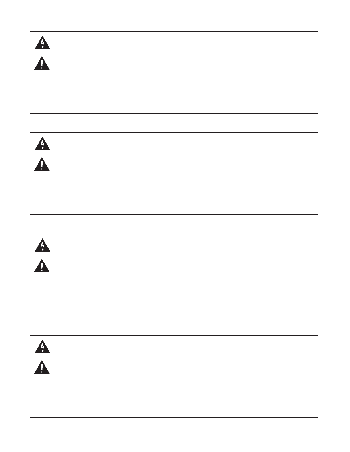
MUTE (18)
Channels can be muted individually by shorting this terminal to ground. It provides approximately 45 dB of
attenuation.
figure 1 Mute
STATUS OUTPUT (19)
The status is a DC logic output that is low (0 volts) when the channel is active and high (3.8 volts) when the
channel is not active. This DC voltage can be used to key video cameras or trigger key lights on active
microphones.
LOOP (Channels 1 and 2) (20)
This is a signal loop that allows an external device such as an EQ to be inserted into the signal path of the
first two channels. When used without external processing these loops are hardwired.
CEQ 280
IN
figure 2 Loop
OUT
MUTEBUS (21)
The Mutebus is a control port that when shorted to ground will mute all channels that are assigned to the
mutebus (approximately 45 dB). The channels to be muted must be attached to the mutebus using the
internal switch marked OFF/MBUS. (See number 7).
figure 3 Mutebus
7
Page 8
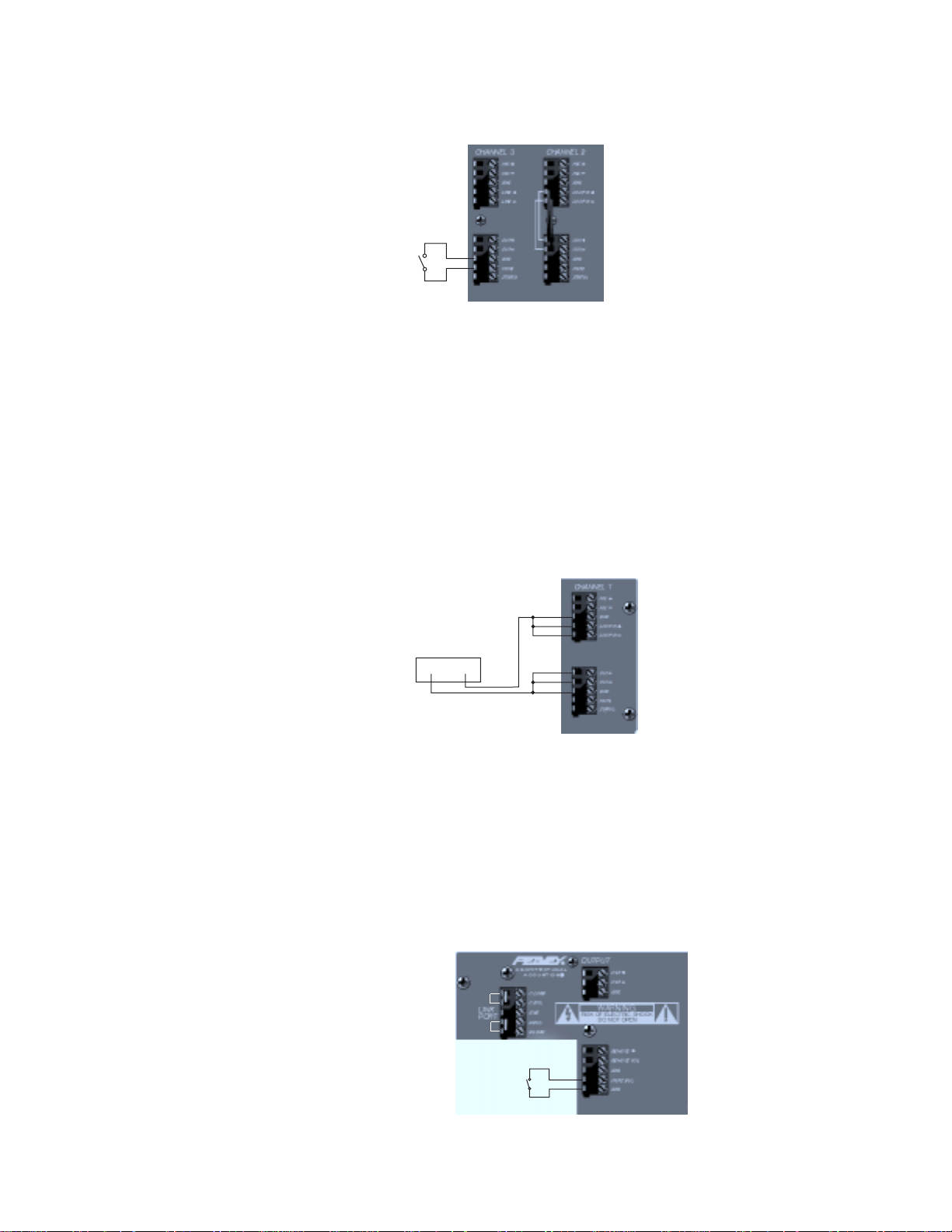
REMOTE VOLUME (22)
The master level of the mixer can be controlled remotely with a simple connection on the back of the unit. A
10 K to 100 K potentiometer can be wired as shown in the drawing below. A 10 K pot will provide approximately 0 to 25 dB of attenuation. A 100 K pot will provide 0 to 45 dB of attenuation. If desired, a control
voltage can be inserted to command 0 to 70 dB of attenuation. The internal gain trim must be set full CW to
achieve the maximum attenuation range of the remote volume.
NOTE: The control voltage should never exceed 13 volts DC.
figure 4 Remote Volume
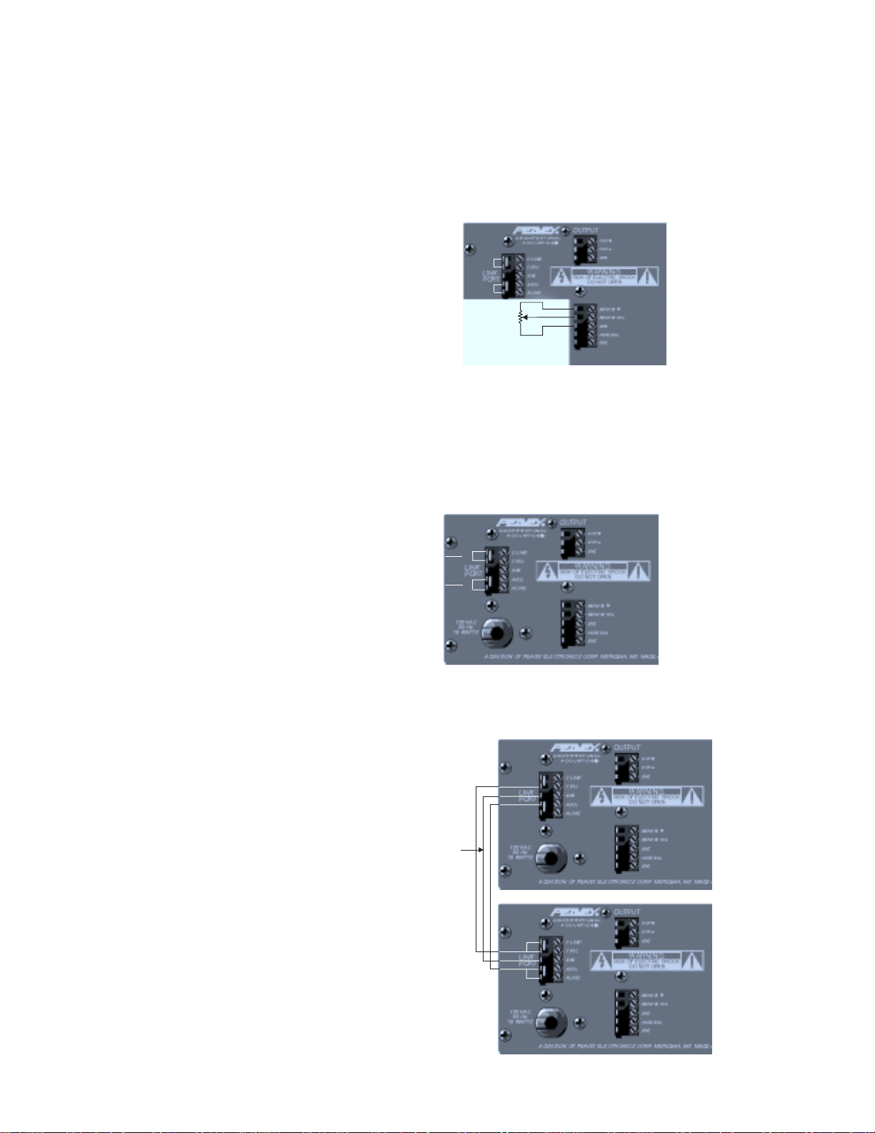
LINK PORT (23)
To increase the number of inputs available, multiple Peavey Automix's can be linked together. Linking
automixers is a very simple process. It can be done with a small flathead screwdriver and a length of two
conductor shielded wire.
a. Using the small screwdriver, remove the factory installed jumper wires in the link port from the slave
unit.
remove »
remove »
figure 5 Link Port
b. Connect the mixers with the shielded wire as shown.
figure 6 Link Port
SHIELD
»
»
8
Page 9

You now have a 16 (or more) channel automatic mixer. Any unit can be used for the system output. The
notch filter and master controls will only affect that unit's output.
NOTE: When configuring multiple units, the wire jumpers in the ALOAD and the CLOAD must be left in one
unit and one unit only.
MASTER OUTPUT (24)
The master output is a 600 ohm, transformer balanced output that can be used to feed an external power
amplifier. It is at this point that the automatically mixed or the manually mixed output is accessed.
SETTING UP THE AUTOMIX
1. Wiring Inputs and Outputs:
For best results it is recommended that a two-conductor shielded cable is used for all input and output
connections. When making connections remember to observe proper polarity. The recommended strip
length for the screw terminal connectors is 1/2".
2. Initial Control Settings:
Channel Levels (Faceplate) - (Full CCW)
Channel Gain Trims (Internal) - (Full CCW)
Priority (Internal) - (Full CCW)
Notch Controls (Internal) - (Full CCW)
Downward Expander (Internal) - (Full CCW)
Master Level (Faceplate) - (Full CW)
Master Level (Internal) - (Full CCW)
All channels in auto mode
3. Setting the Channel Level:
Set the front panel control (of the channel that is being adjusted) to the middle (12 o’clock) position. Connect
a mic or line input to one channel. While someone is speaking into the mic (in a way that it would normally
be used), slowly increase the channel gain trim until a slight ringing (feedback) is heard. Turn the channel
gain trim down slowly until the ringing is no longer audible. This is the maximum level that the gain trim
should be set. Turn the external channel level control down (full CCW).
NOTE: The internal master gain trim may need to be turned up (CW) if the channels can be easily driven
into clipping, or feedback cannot be obtained in the normal operating range of the internal gain trim control.
Repeat this step for the remaining channels.
4. Return all of the external channel level controls to their mid position (0).
5. Setting the Notch Filter:
The Notch Filter can be set in several different ways. It can be set using test equipment to pinpoint frequencies that are prone to feedback, or it can be set “by ear.” For the purpose of this manual the “by ear” method
will be described.
a. Slowly increase the master gain trim (internal) until a slight ringing is audible.
b. Select the proper frequency range and turn the corresponding level control CW to about the 12 o’clock
position.
c. Slowly turn the frequency control back and forth until the ringing is no longer audible.
d. Again slowly increase the master gain trim until ringing is heard. If this is a different frequency, repeat
steps 2 and 3. If it is not a different frequency, try turning the frequency control while listening to the
feedback. Stop when the frequency that is feeding back is reduced. If the feedback is still audible turn
the level control CW toward the -15 until the feedback is gone.
e. Set the Master Level Control (external) for the desired overall output level. The mixer’s levels are now
set and the mixer’s other features (downward expander, Lo cut and priority) can be set as desired for
the application.
f. Attach the security plexiglass with the four supplied screws. This will prevent any unwanted tampering
with the settings.
9
Page 10

SPECIFICATIONS
Nominal Out = +2 dBu (1 volt)
PREAMP SPECS
EIN:
-122 dBu (terminated 150 ohms)
PREAMP GAIN RANGE:
25 dB to 55 dB
INPUT IMPEDANCE: (MIC and LINE)
2,000 ohms (transformer balanced)
PHANTOM POWER:
+12 volts at Mic ± terminals
INPUT SENSITIVITY:
-65 dBu
PRIORITY (Channels 1 & 2):
0 dB to 9 dB
FREQUENCY RESPONSE:
20 Hz to 20 kHz, +1/-2 dB at nominal
MAXIMUM OUTPUT LEVEL:
+20 dBu (Hi-Z load)
+16 dBm (600 ohm load)
REMOTE VOLUME RANGE:
0 dB to 70 dB of attenuation
OFF CHANNEL ATTENUATION:
0 dB to -70 dB
MUTE:
Channel is attenuated 45 dB when mute to ground
connection is made.
MUTEBUS:
Multiple channels can be attenuated 45 dB when
mutebus to ground connection is made.
LOW CUT FILTER:
-3 dB at 75 Hz (6 dB per octave)
COMMON MODE (rejection ratio):
-85 dB
GENERAL SPECS
OUTPUT IMPEDANCE (transformer balanced):
600 ohms (nominal)
DISTORTION:
< 0.1 % at nominal
STATUS OUPUT:
Status is low (0 V) when channel is active. It is
high (3.8 V) when channel is not active.
POWER CONSUMPTION:
AC 120 volts, 60 Hz Domestic
AC 230 volts, 50/60 Hz Export
15 watts
WEIGHT:
10.8 lbs
DIMENSIONS:
3-1/2" H x 17" W x 10-1/8" D
TM
®
Due to our efforts for constant improvements,
features and specifications listed herein are subject to change without notice.
10
Page 11

Flow Diagram
11
Page 12

E S P A Ñ O L
Consulte los diagramas del panel
delantero en la sección de inglés de este manual.
¡Gracias por tu compra de la Automix™! La Architectural Acoustics Automix es una mezcladora automática
de alta calidad con ocho entradas de micrófono/línea balanceadas por transformador. Cada preamplificador
de micrófono/línea ofrece control de ganancia, refuerzo de potencia (phantom power) (para las entradas de
micrófono); filtro de corte de graves, indicador LED de actividad/recorte por sobrecarga, y la opción entre
operación manual o automática. Se puede apagar externamente el sonido de cada canal o de múltiples
canales por medio de un bus de apagado de sonido externo. Además, los canales uno y dos ofrecen
prioridad ajustable y un circuito para procesador de señal. La sección maestra proporciona un control de
recorte de ganancia, filtros de barrido de recorte de muesca de 3/4 de octava, un expansor descendente,
una salida balanceada por transformador y un puerto para control de volumen remoto.
La Automix ha sido diseñada de manera que se puedan enlazar fácilmente múltiples unidades para formar
una sola mezcladora de muchas más entradas (16, 24, 32…). La Automix está equipada con una cubierta
de seguridad de plexiglás traslúcido para evitar cambios a los ajustes del instalador. La Automix se empaca
como unidad autónoma, pero también se puede montar en un bastidor estándar de 48.26 cm con el juego
opcional para montaje en bastidor.
TEORÍA DE OPERACIÓN
La Peavey Automix es una “mezcladora automática” clásica que combina varias técnicas ya probadas por el
tiempo para proporcionar una ganancia máxima antes de retroalimentación en una configuración fácil de
ajustar y fácil de usar.
La Automix cuenta con dispositivos amplificadores controlados por voltaje (VCA) y circuitos de cálculo de
ganancia en cada canal para bajar la ganancia al activarse más micrófonos. Al hacer caer la ganancia en
3 dB cada vez que se dobla el número de micrófonos activos, el nivel global de ganancia del sistema
permanece en la unidad para un desempeño de ganancia ideal antes de retroalimentación.
Un rectificador de precisión y convertidor logarítmico calcula la amplitud de la señal de audio presente en
cada micrófono en tiempo real. Esta amplitud de canal, en decibeles, es comparada entonces con la
amplitud de la suma de todos los canales, también en decibeles. Un sencillo circuito de cómputo calcula la
diferencia matemática entre estas dos amplitudes y alimenta el resultado al VCA como una señal de control
de ganancia.
Para entender mejor cómo funciona esto, permíteme darte unos cuantos ejemplos. Si tenemos el caso de
una persona hablando en un micrófono, la amplitud en ese canal será virtualmente idéntica a la amplitud de
“la suma de todos los canales.” La diferencia entre esas dos amplitudes equivalentes es “0.” Cuando se
alimentan 0 dB al puerto de control VCA el resultado es una ganancia de la unidad para ese canal. Todos
los demás canales, sin nadie hablando, exhibirán amplitudes significativamente menores. Cuando se
comparan con la “suma,” que contiene una señal nominal, tienen como resultado números negativos. Estos
números negativos presentados a los dispositivos VCA de los canales inactivos, ordenan una mayor
atenuación de ruido y fuga presentes en estos canales inactivos.
Un segundo y más interesante ejemplo es dos personas hablando simultáneamente. Para simplificar este
ejemplo, asumamos que ambas están hablando al mismo volumen. Como estas dos fuentes son
incoherentes, p.ej. no idénticas, sumarán como la raíz cuadrada de la suma de los cuadrados o 3 dB más
que cualquiera de las dos individualmente. Cuando la amplitud de cada canal se compara con esta suma de
+3 dB, se ordenará a su VCA que atenúe en 3 dB. Como en el ejemplo anterior, los canales inactivos serán
12
Page 13

atenuados aún más. La elegancia de este enfoque es realmente evidente en este siguiente caso. Asume
que una persona está situada exactamente a la misma distancia de dos micrófonos. La señal idéntica que
llega a cada micrófono, al ser coherente, sumará linealmente +6 dB en la suma de todos los canales. Esto
tiene como resultado que se baje en 6 dB a los dos canales. Al ser coherentes, estas dos señales idénticas
con una suma de -6 dB darán como resultado la unidad.
Estas relaciones de ganancias son válidas sin importar cuántos micrófonos estén activos, ni si las señales
son coherentes o no. Ya que estos cálculos son realizados en el dominio logarítmico, no importa cuáles
sean las amplitudes reales, sino solamente las amplitudes relativas entre señales.
FUNCIONES DEL TABLERO FRONTAL
CHANNEL LEVEL (Nivel de canal) (1)
Modo manual: En el modo manual, el control de Nivel de canal proporciona 6 dB de ganancia sobre la
unidad nominal y 50 dB de atenuación.
Modo automático: En modo automático, los controles aún ofrecen 50 dB de atenuación, pero el control
no agrega ganancia al nivel global del sistema. Más bien, cuando el nivel se ajusta sobre 0, los otros
canales son atenuados para hacer que el canal suene con más volumen en la mezcla sin aumentar la
ganancia del sistema.
MASTER VOLUME (Volumen maestro) (2)
El “Control maestro” controla el nivel de volumen global. La gama se fija en 10 dB de ganancia sobre la
unidad nominal y 40 dB de atenuación por debajo de ésta.
Nota: La gama de operación de este control es reducida por el ajuste del recorte de ganancia interno.
POWER SWITCH (Interruptor de corriente) (3)
Oprima el interruptor a la posición “on.” El indicador LED rojo se encenderá para indicar que se está
alimentando corriente a la unidad.
FUNCIONES DEL PANEL FRONTAL INTERNO
PRIORITY (Prioridad [Sólo en los canales 1 y 2]) (4)
Al girar hacia la derecha el control de “prioridad” se permite que un canal sobrepase a los demás. Esto se
logra haciendo creer a los circuitos de cálculo de ganancia que este canal tiene más volumen que los
demás. Hay hasta 9 dB de prioridad disponible.
GAIN TRIM (Recorte de ganancia) (5)
Este control fija la ganancia de entrada en cada preamplificador. El monto de ganancia es ajustable desde
+25 dB hasta +55 dB (entrada de micrófono).
DIP SWITCHES (Interruptores empotrados)
Cada canal tiene un interruptor empotrado de cuatro unidades que controla las siguientes funciones de
cada canal.
MAN/AUTO (MANUAL/AUTOMÁTICO) (6)
Este interruptor determina si el canal está operando en modo automático o manual.
OFF/MBUS (APAGADO/BUS DE APAGADO DE SONIDO) (7)
Este interruptor se usa para conectar el canal al bus de apagado de sonido del sistema. Esto permite que
se apague el sonido a múltiples canales bajo control externo. NOTA: ver BUS DE APAGADO DE SONIDO.
LO CUT/FLAT (RECORTE DE GRAVES/PLANO) (8)
Este interruptor selecciona el filtro de recorte de graves. Este filtro proporciona una reducción de las
frecuencias bajas que ayuda a minimizar ruido indeseado (manipulación de micrófonos, golpes en la mesa,
etc.). La reducción comienza a los 75 Hz (-3 dB) y es un filtro de 6 dB por octava.
13
Page 14

OFF/PHAN (APAGADO/REFUERZO DE POTENCIA) (9)
Cuando este interruptor está en la posición de REFUERZO DE POTENCIA, se proporciona un refuerzo de
potencia de +12 volts a las terminales ± de micrófono. Esto proporciona potencia para micrófonos de
condensador y debe anularse cuando se usen micrófonos dinámicos o entradas sin balance.
ACTIVE/CLIPPING LED (Activo/Indicador LED de recorte por sobrecarga) (10)
El indicador LED brillará en verde cuando el canal esté activo y el estátus de salida sea bajo (0 V). El
indicador LED comenzará a brillar en rojo 3 dB antes de que el preamplificador comience a sobrecargarse.
NOTCH FILTER LEVEL AND FREQUENCY CONTROLS (Nivel de filtro de muesca y Controles de
frecuencia) (11 y 12)
Estos filtros pueden ser usados para atenuar las frecuencias que tienden a retroalimentarse sin afectar
adversamente la calidad tonal del sistema. Ecualizar estas frecuencias problema fuera de la respuesta de la
sala a las frecuencias aumenta la ganancia del sistema de sonido antes de retroalimentación.
Control de nivel del filtro de muesca (11): El control de nivel del filtro de muesca consiste en tres filtros
de barrido de 1/3 de octava con recorte de 0 a 15 dB. Este control ajusta el monto de recorte a la
frecuencia seleccionada por en control de frecuencia correspondiente (12).
Control de frecuencia del Filtro de muesca (12): El control de frecuencia del filtro de muesca se usa
para seleccionar la frecuencia central del filtro de muesca. El filtro inferior tiene una gama de 40 Hz a
925 Hz; el filtro intermedio tiene una gama de 260 Hz a 6 kHz; el filtro superior tiene una gama de 500 Hz
a 12 kHz.
DOWNWARD EXPANDER (Expansor descendente) (13)
El expansor descendente puede usarse para atenuar la ganancia del sistema cuando todas las señales de
entrada sean bajas. Esto puede usarse para evitar que se amplifique el ruido de fondo de la sala.
Setting the Downward Expander (Ajuste del expansor descendente):
Haz que alguien hable en un micrófono al nivel más bajo que esperes encontrar. Lentamente gira a la
derecha el control del expansor descendente hasta que se atenúe el ruido de fondo entre las palabras. Ten
cuidado de no ir demasiado lejos. Mientras más expansor descendente se use, menos “natural” será el
sonido del sistema.
Este método te dará un buen punto de partida, pero la mejor manera de ajustar el expansor descendente es
durante la junta o evento reales. Al hacer esto, se puede ajustar el expansor descendente para el mejor
sonido. Si tienes que tratar con eventos que sean tanto altos como bajos de volumen, tendrás que sacrificar
un ambiente de sonido natural en favor de menor ruido de fondo.
MASTER GAIN TRIM (Recorte de ganancia maestro) (14)
Este control fija la ganancia global máxima del sistema y debe fijarse con el control maestro de ganancia del
tablero frontal al máximo (todos los canales en la unidad) y los amplificadores de potencia externos
encendidos y bloqueados sus ajustes de operación. Cuando esté recortado a un margen seguro por debajo
de retroalimentación, ninguna combinación de controles del usuario podrá causar retroalimentación. Este
recorte ofrece hasta 25 dB de atenuación.
Tablero Trasero:
2423 15
16
21
22
17
18 19 20
14
Page 15

FUNCIONES DEL TABLERO TRASERO
MIC INPUTS (Entradas de micrófono) (15)
Para usarse con micrófonos de baja impedancia o fuentes de bajo nivel. Éstas son entradas balanceadas
por transformador con una impedancia de 2,000 ohms.
LINE IMPUTS (Entradas de línea [Canales del 3 al 8]) (16)
Éstas permiten que se usen entradas de línea en los canales del 3 al 8. Éstas son entradas balanceadas
por transformador a través de un acentuador de resistencia de 30 dB. La impedancia de entrada es de
2,000 ohms.
DIRECT OUTPUTS (Salidas directas) (17)
Cada canal tiene un juego de terminales de salida directa que pueden usarse para grabación o en cualquier
momento que se requiera una salida de un canal individual. El nivel de esta señal es independiente de las
manipulaciones de ganancia de la “Automix.”
MUTE (Apagado de sonido) (18)
A todos los canales se les puede apagar el sonido individualmente al cortar a tierra esta terminal.
Proporciona aproximadamente 45 dB de atenuación.
Ver la figura 1, Apagado de sonido, de la sección en inglés
STATUS OUTPUT (Salida de estátus) (19)
El estátus es una salida lógica de CC que es baja (0 volts) cuando el canal está activo, y alta (3.8 volts)
cuando el canal está inactivo. Este voltaje de CC puede usarse para encender cámaras de vídeo o disparar
luces de aviso en micrófonos activos.
LOOP (Circuito externo [Sólo canales 1 y 2]) (20)
Éste es un circuito de señal que permite que se inserten dispositivos externos, tales como un ecualizador,
en la ruta de la señal de los dos primeros canales. Cuando se usan sin procesamiento externo, estos
circuitos están cerrados.
Ver la figura 2, Circuito externo, de la sección en inglés
MUTEBUS (Bus de apagado de sonido) (21)
El bus de apagado de sonido es un puerto de control que cuando se corta a tierra el circuito apagará el
sonido de todos los canales que estén asignados a él (aproximadamente 45 dB). Los canales a los que se
les apague el sonido deben ser conectados al bus de apagado de sonido usando el interruptor interno
marcado APAGADO/BUS DE APAGADO DE SONIDO.
Ver la figura 3, Bus de apagado de sonido, de la sección en inglés
REMOTE VOLUME (Volumen remoto) (22)
Se puede controlar remotamente el volumen maestro de la mezcladora con una sencilla conexión al lado
posterior de la unidad. Se puede conectar un potenciómetro de 10 K a 100 K como se muestra en el dibujo
de abajo. Un potenciómetro de 10 K proporcionará aproximadamente de 0 a 25 dB de atenuación. Un
potenciómetro de 100 K proporcionará aproximadamente de 0 a 45 dB de atenuación. Si se desea, se
puede insertar un voltaje de control para controlar de 0 a 70 dB de atenuación. El recorte de ganancia
interno debe estar totalmente hacia la derecha para lograr la gama máxima de atenuación del volumen
remoto. NOTA: El voltaje de control nunca debe exceder los 13 volts de CC.
Ver la figura 4, Volumen remoto, de la sección en inglés
15
Page 16

LINK PORT (Puerto de enlace) (23)
Se pueden enlazar múltiples Automixes para aumentar el número de entradas disponibles. Enlazar
automixes es un proceso muy sencillo, Puede hacerse con un destornillador plano pequeño y un largo de
cable blindado de dos conductores.
a. Usando el destornillador pequeño, retira los cables de puente instalados en la fábrica del puerto de
enlace de la unidad secundaria.
Ver la figura 5, Puerto de enlace, de la sección en inglés
b. Conecta las mezcladoras con el cable blindado como se muestra.
Ver la figura 6, Puerto de enlace, de la sección en inglés
Ahora ya tienes una mezcladora automática de 16 (o más) canales. Se puede usar cualquier unidad para la
salida del sistema. El filtro de muesca y los controles maestros sólo afectarán la salida de esa unidad.
NOTA: Al configurar múltiples unidades, los cables de puente en la CARGA A y la CARGA C deben dejarse
en una unidad y solamente en una unidad.
MASTER OUTPUT (Salida maestra) (24)
La salida maestra es una salida de 600 ohms balanceada por transformador que puede ser usada para
alimentar un amplificador de potencia externo. Es en este punto donde se puede acceder a la salida
mezclada manual o automáticamente.
SETTING UP THE AUTOMIX (Ajuste de la Automix)
1. Cableado de entradas y salidas:
Para los mejores resultados, se recomienda usar cable blindado de dos conductores para todas las
conexiones de las entradas y salidas. Recuerda observar la polaridad correcta al hacer las conexiones. El
largo recomendado de la punta desnuda del cable para las conexiones terminales de tornillo es de 1.27 cm.
2. Ajustes iniciales de los controles:
Niveles de canal (Placa frontal) - (Todo a la izquierda)
Recortes de ganancia de canal (Interno) - (Todo a la izquierda)
Prioridad (Interno) - (Todo a la izquierda)
Controles de muesca (Interno) - (Todo a la izquierda)
Expansor descendente (Interno) - (Todo a la izquierda)
Nivel maestro (Placa frontal) - (Todo a la derecha)
Nivel maestro (Interno) - (Todo a la izquierda)
Todos los canales en modo automático
3. Ajuste del Nivel de canal:
Ajusta el control del tablero frontal (del canal que se está ajustando) a la posición intermedia (12 en punto).
Conecta una entrada de micrófono o línea a un canal. Mientras que alguien está hablando en el micrófono
(de la misma manera en que se usaría normalmente), aumenta lentamente el recorte de ganancia hasta
que sea audible un ligero zumbido agudo (retroalimentación). Baja lentamente el recorte de ganancia hasta
que el zumbido agudo deje de oírse. Éste es el nivel máximo al que debe ajustarse el recorte de ganancia.
Baja el control de ganancia interno (todo a la izquierda).
NOTA: Es posible que sea necesario subir el recorte de ganancia maestro interno (a la derecha) si se
puede hacer que el canal se sobrecargue fácilmente, o que no se pueda obtener retroalimentación en la
gama de operación normal del control de recorte de ganancia interno. Repite este paso con los canales
restantes.
4. Vuelve a poner todos los controles externos de volumen de canal en su posición intermedia (0).
5. Ajuste del filtro de muesca:
El filtro de muesca puede ajustarse en un par de maneras. Puede ajustarse usando equipo de pruebas para
localizar las frecuencias que tiendan a retroalimentarse, o puede ajustarse “de oído.” Para el propósito de
este manual, sólo será descrito el método “de oído.”
16
Page 17

a. Incrementa lentamente el recorte de ganancia maestro (interno) hasta que se oiga un ligero
zumbido agudo.
b. Selecciona la gama de frecuencia apropiada y gira el control correspondiente hacia la derecha
hasta alrededor de la posición de las 12 en punto.
c. Gira lentamente el control de frecuencia hacia derecha e izquierda hasta que ya no se oiga el
zumbido agudo.
d. De nuevo, aumenta lentamente el recorte de ganancia maestro hasta que se oiga el zumbido
agudo. Si esta es una frecuencia diferente, repite los pasos 2 y 3. Si no lo es, prueba girando el
control de frecuencia mientras escuchas la retroalimentación. Deténte cuando se reduzca la
frecuencia que se está retroalimentando. Si la retroalimentación aún es audible, gira el control de
nivel hacia la derecha hacia el -15 hasta que desaparezca la retroalimentación.
e. Fija el Control de nivel maestro (externo) al nivel de salida global deseado. Los niveles de la
mezcladora ya están ajustados y las demás funciones de la mezcladora (expansor descendente,
corte de graves y prioridad) pueden ajustarse como se desee para la aplicación.
f. Sujeta el plexiglás de seguridad con los cuatro tornillos incluidos. Esto evitará cualquier
manipulación no autorizada de los ajustes.
17
Page 18

F R A N C A I S
Veuillez vous référer au "front panel art"
situé dans la section en langue anglaise de ce manuel.
Merci d’avoir choisi l’Automix‘ ! L’Automix, conçu par Architectural Acoustics, est un mélangeur automatique
de haute qualité, équipé de huit entrées Micro/Ligne symétrisées par transformateur. Chaque préampli
Micro/Ligne offre une commande de gain, une alimentation fantôme (pour les entrées mic), un filtre de
coupure bas, une DEL d’activité/écrêtage, ainsi que le choix entre un mode de fonctionnement automatique
ou manuel. Chaque canal peut être assourdi (mute) de l’extérieur, tout comme un groupe de canaux peut
être assourdi de l’extérieur au moyen d’un mutebus programmable. En outre, les canaux un et deux
possèdent une priorité réglable et une boucle pour processeur de signal. La section maître offre une
mollette de commande de gain, trois filtres coupe-bande paramétrables d’1/3 d’octave, un sur-atténuateur
des niveaux bas (downward expander), une sortie symétrisée par transformateur, ainsi qu’une prise
permettant la commande du volume à distance.
L’Automix a été conçu de manière à permettre la connexion de plusieurs unités pour réaliser un mélangeur
unique offrant beaucoup plus d’entrées (16, 24, 32…). L’Automix est équipé d’un panneau de sécurité de
plexiglas empêchant tout changement non désiré des réglages effectués par l’installateur ; son
conditionnement en fait un appareil autonome, mais il est également possible de le monter sur un rack
standard de 48,25 cm (19 po.) grâce au kit optionnel de montage sur rack.
UN MOT DE THEORIE
L’Automix de Peavey est un «mélangeur automatique» classique qui réunit des techniques éprouvées
délivrant un gain maximum avant retour, dans une configuration de mise en œuvre et d’utilisation faciles.
Pour chacun des canaux, l’Automix utilise des VCA (amplificateurs contrôlés en tension) et des circuits de
calcul de gain permettant de diminuer celui-ci au fur et à mesure que le nombre de microphones actifs
augmente. En diminuant le gain de 3 dB chaque fois que ce nombre double, le gain global du système est
maintenu à la valeur unité, qui est le gain avant retour idéal pour la performance.
Un rectificateur de précision et un convertisseur logarithmique calculent en temps réel, pour chacun des
canaux, l’amplitude du signal audio de chaque microphone. L’amplitude du canal, mesurée en décibels, est
alors comparée à celle de la somme de tous les canaux, également mesurée en décibels. Un circuit
élémentaire calcule la différence mathématique entre ces deux amplitudes, et fournit au VCA le résultat qui
sert de signal de contrôle de gain.
Pour mieux comprendre comment cela fonctionne, prenons quelques exemples. Lorsqu’une personne parle
dans un microphone, l’amplitude du canal est quasiment identique à celle de «la somme de tous les
canaux». La différence entre ces deux amplitudes égales est «0». Si l’entrée de commande du VCA est
alimentée par 0 dB, le résultat est un gain unité pour ce canal. L’amplitude de tous les autres canaux est
beaucoup plus faible, puisque personne d’autre ne parle. En effet, la comparaison de leur amplitude (nulle)
à celle de la «somme», qui contient un signal nominal, produit des nombres négatifs. Ceux-ci, présentés aux
VCA des canaux inactifs, imposent une atténuation supplémentaire du bruit et des parasites présents sur
ces canaux.
18
Page 19

Un deuxième exemple, plus intéressant, est celui de deux personnes parlant simultanément. Pour simplifier
cet exemple, supposons qu’elles parlent aussi fort l’une que l’autre. Puisque ces deux sources ne sont pas
cohérentes (c’est-à-dire pas identiques), l’amplitude totale est la racine carrée de la somme des carrés de
leurs amplitudes, soit exactement 3 dB de plus que chacune des amplitudes prises séparément. Lorsque
l’amplitude de chacun de ces deux canaux est comparée à cette somme, leur VCA commande une
atténuation de 3 dB. Comme précédemment, les canaux inactifs subissent une atténuation supplémentaire.
Ce n’est que dans le cas suivant que l’élégance de cette approche se révèle pleinement : supposons qu’une
personne soit située à égale distance de deux microphones. Un signal identique arrive dans les deux
canaux ; ces signaux étant cohérents, la sommation linéaire de tous les canaux vaut 6 dB de plus que
l’amplitude de chaque canal. Il en résulte une atténuation de +6 dB pour chaque canal. Atténués de 6 dB, la
somme de ces deux signaux identiques produit un gain unité.
Ces relations de gains restent vraies, quel que soit le nombre de microphones actifs, que les signaux soient
cohérents ou non. Tous les calculs étant effectués dans le domaine logarithmique, les amplitudes absolues
des signaux importent peu ; seules comptent leurs amplitudes relatives.
CARACTERISTIQUES DU PANNEAU AVANT
CHANNEL LEVEL (Niveau du canal) (1)
Mode manuel : en mode manuel, la commande de niveau du canal permet un gain de 6 dB au-dessus de
l’unité nominale et une atténuation de 50 dB.
Mode auto : en mode automatique, cette commande offre toujours une atténuation de 50 dB, mais elle ne
permet pas d’augmenter le niveau de gain global du système. En effet, lorsque le niveau est réglé audessus de 0, celui des autres canaux est atténué, ce qui renforce l’intensité de ce canal sans modifier le
gain du système.
MASTER VOLUME (Volume maître) (2)
La commande «Volume Master» contrôle le niveau de sortie global. Il peut varier entre 40 dB d’atténuation
en dessous du gain unité et 10 dB de gain au dessus.
Remarque : La plage de valeurs de cette commande peut être réduite par le réglage de la mollette de gain
interne.
POWER SWITCH (Interrupteur d’alimentation) (3)
Appuyez sur l’interrupteur pour l’amener en position marche («on»). La DEL rouge s’illumine pour indiquer
que l’appareil est alimenté.
CARACTERISTIQUES DU PANNEAU INTERNE
PRIORITY (Priorité [Canaux 1 et 2 uniquement]) (4)
Si la mollette «priorité» est tournée dans le sens des aiguilles d’une montre, le canal correspondant prend le
pas sur les autres. Cela fait en effet croire aux circuits de calcul du gain que l’amplitude de ce canal est
supérieure à celle des autres. Il est possible d’obtenir jusqu’à 9 dB de priorité.
GAIN TRIM (Réglage de gain) (5)
Cette mollette fixe le gain en entrée de chaque préampli. Le niveau du gain est réglable de +25 dB à +55 dB
(entrée Mic).
DIP SWITCHES (Sélecteurs DIP)
Chaque canal est muni d’un banc de quatre sélecteurs qui contrôlent individuellement les fonctions
suivantes.
MAN/AUTO (6)
Ce sélecteur détermine si le canal fonctionne en mode manuel ou automatique.
19
Page 20

OFF/MBUS (7)
Ce sélecteur permet de connecter le canal au mutebus du système. Cela permet d’assourdir plusieurs
entrées sous commande externe. REMARQUE : voir MUTEBUS.
LO CUT/FLAT (8)
Ce sélecteur permet d’activer le filtre de coupure basse. Ce filtre permet une atténuation des basses
fréquences, qui contribue à éliminer les bruits indésirables (prise en main des micros, chocs sur la table,
etc.). L’atténuation commence à 75 Hz (-3 dB) ; la pente du filtre est de 6 dB par octave.
OFF/PHAN (9)
Lorsque ce sélecteur est en position PHAN, une alimentation fantôme de + 12 volts est appliquée aux
bornes ± de l’entrée Mic. Cette alimentation convient aux micros à condensateur ; elle doit être désactivée si
vous utilisez des microphones dynamiques ou des entrées asymétriques.
ACTIVE/CLIPPING (DEL d’activité/écrêtage) (10)
Cette DEL est de couleur verte si le canal est actif et le niveau de sortie bas (0 V). Elle passe au rouge
lorsque le niveau de sortie est inférieur de 3 dB au niveau d’écrêtage du préampli.
NOTCH FILTER LEVEL AND FREQUENCY CONTROLS (Commandes de niveau et de fréquence
du filtre coupe-bande) (11 et 12)
Ces filtres permettent d’atténuer les fréquences sujettes à une rétroaction parasite, sans altérer la qualité
sonore du système. Une égalisation de ces fréquences à problèmes adaptée à la réponse en fréquence de
la salle permet d’augmenter le gain du système avant retour.
Réglage du niveau du filtre coupe-bande (11) : le système de réglage du niveau du filtre coupe-bande
se compose de trois filtres d’1/3 d’octave, à fréquence centrale paramétrable, permettant une atténuation
de 0 à 15 dB. Cette mollette ajuste le niveau d’atténuation pour la fréquence choisie par la mollette de
réglage de fréquence correspondante (12).
Réglage de la fréquence du filtre coupe-bande (12) : la mollette de réglage de la fréquence du filtre
coupe-bande permet de choisir la fréquence centrale du filtre. La bande de fréquences du filtre des graves
s’étend de 40 Hz à 925 Hz ; celle du filtre des moyens est comprise entre 260 Hz et 6 KHz. Enfin, celle du
filtre des aigus va de 500 Hz à 12 KHz.
DOWNWARD EXPANDER (Sur-atténuateur des niveaux bas) (13)
Le sur-atténuateur des niveaux bas sert à atténuer le gain du système lorsque tous les signaux d’entrée
sont faibles. Cela permet d’éviter l’amplification des bruits de fond de la salle.
Setting the Downward Expander (Réglage du sur-atténuateur des niveaux bas) :
Demandez à quelqu’un de parler dans un microphone, de la voix la plus faible que vous pensez obtenir.
Tournez lentement la mollette dans le sens des aiguilles d’une montre jusqu’à ce que le bruit de fond
perceptible entre les mots soit atténué. N’allez toutefois pas trop loin : plus l’action du sur-atténuateur est
importante, moins le son produit par le système sera «naturel».
Cette méthode vous donnera un bon point de départ, mais le meilleur moment pour régler le sur-atténuateur
est lors d’une conférence ou d’un spectacle. C’est dans ces conditions que vous pourrez régler le suratténuateur pour obtenir le meilleur son. Si vous êtes confronté à des situations où le son peut être
alternativement fort et faible, vous devrez trouver un compromis entre le naturel des sonorités et le niveau
du bruit ambiant ou du bruit de fond.
MASTER GAIN TRIM (Atténuateur de gain master) (14)
Cette mollette permet de régler le gain maximum global du système ; pour ajuster cette mollette, le niveau
de gain master du panneau avant doit être poussé au maximum (gain unité pour tous les canaux) ; il faut
également que les amplificateurs de puissance externes soient sous tension et verrouillés à leur niveau
opérationnel. Lorsque cet atténuateur est réglé avec une marge de sécurité suffisante en dessous du niveau
déclenchant des rétroactions parasites, aucune combinaison de réglages utilisateur ne peut provoquer de
rétroactions. Cette mollette permet une atténuation maximale de 25 dB.
20
Page 21

Panneau Arrière :
2423 15
21
22
16
17
18 19
20
CARACTERISTIQUES DU PANNEAU ARRIERE
MIC INPUTS (Entrées Mic) (15)
Elles sont destinées à être utilisées par les microphones à basse impédance ou par des sources de signal
de faible niveau. Ce sont des entrées symétrisées par transformateur; leur impédance est de 2.000 ohms.
LINE INPUTS (Entrées Ligne [canaux 3-8]) (16)
Ces prises acceptent des entrées de niveau ligne pour les canaux 3 à 8. Ce sont des entrées symétrisées
par transformateur, munies d’un atténuateur résistif de 30 dB. L’impédance d’entrée est de 2.000 ohms.
DIRECT OUTPUTS (Sorties directes) (17)
Chaque canal possède des bornes de sortie directe, utilisables pour l’enregistrement ou à chaque fois que
la sortie d’un canal particulier est nécessaire. Le niveau de ce signal est indépendant des manipulations de
gain par «Automix».
MUTE (18)
Chaque canal peut être assourdi individuellement en connectant cette borne à la masse. Elle offre une
atténuation d’environ 45 dB.
Voir Mute sur la figure 1 de la section Anglais
STATUS OUTPUT (Sortie d’état) (19)
Cette sortie présente un signal à courant continu à deux états : bas (0 volt) si le canal est actif, et haut
(3,8 volts) si le canal n’est pas en activité. Cette sortie permet de déclencher des caméras vidéo ou
d’allumer un indicateur lumineux sur les microphones actifs.
LOOP (Boucle [canaux 1 et 2 uniquement] (20)
Il s’agit d’une boucle de signal qui permet d’intercaler un appareil externe, tel qu’un égaliseur, sur le chemin
du signal des deux premiers canaux. S’il n’est pas fait usage de processeurs externes, ces boucles sont
court-circuitées.
Voir Loop sur la figure 2 de la section Anglais
MUTEBUS (21)
Le MuteBus est une prise de commande qui assourdit tous les canaux affectés au mutebus lorsqu’elle est
connectée à la masse ; l’atténuation est de 45 dB environ. Les canaux à assourdir doivent être connectés
au mutebus à l’aide du sélecteur interne désigné par OFF/MBUS (voir numéro 7).
21
Page 22

Voir Mutebus sur la figure 3 de la section Anglais
REMOTE VOLUME (Commande de volume à distance) (22)
Le niveau master du mélangeur peut être contrôlé à distance grâce à une simple connexion sur le panneau
arrière de l’appareil. Un potentiomètre de 10 K ou 100 K peut être connecté, comme l’indique le schéma cidessous. Un potentiomètre de 10 K permet une atténuation de 0 à 25 dB. Un potentiomètre de 100 K offre
une atténuation comprise entre 0 et 45 dB. Si nécessaire, il est possible d’utiliser une tension de commande
pour obtenir une atténuation variant de 0 à 70 dB. Pour obtenir la plus large plage d’atténuation possible par
commande à distance, il est nécessaire que la mollette de gain du panneau interne soit tournée à fond dans
le sens des aiguilles d’une montre.
REMARQUE : La tension de commande ne doit jamais dépasser 13 volts CC.
Voir Remote Volume sur la figure 4 de la section Anglais
LINK PORT (Bloc de liaison) (23)
Pour multiplier le nombre d’entrées disponibles, il est possible de relier entre eux plusieurs Automix. Ce
processus est très simple ; il suffit d’un petit tournevis à tête plate et d’un câble blindé à deux conducteurs.
a. A l’aide du petit tournevis, retirez les cavaliers installés en usine sur le bloc de liaison de l’appareil
esclave.
Voir Link Port sur la figure 5 de la section Anglais
b. Connectez les mélangeurs avec le câble blindé comme indiqué sur le schéma.
Voir Link Port sur la figure 6 de la section Anglais
Vous obtenez alors un mélangeur automatique à 16 canaux (ou plus). Chaque appareil peut être utilisé
indifféremment pour la sortie. Le filtre coupe-bande et les commandes master n’affecteront que la sortie de
cet appareil.
REMARQUE : Lorsque vous configurez plusieurs appareils, les cavaliers situés dans ALOAD et CLOAD
doivent être laissés dans un seul et unique appareil.
MASTER OUTPUT (Sortie master) (24)
La sortie master est symétrisée par transformateur et son impédance est de 600 ohms. Elle peut être
connectée à un amplificateur de puissance externe. C’est sur cette sortie qu’est disponible le résultat du
mélange automatisé ou manuel.
Setting up the Automix (Installation et mise en œuvre de l’Automix)
1. Câblage des entrées et des sorties :
Pour obtenir des résultats optimaux, il est conseillé d’utiliser des câbles blindés à deux conducteurs pour
toutes les connexions d’entrée et de sortie. Lorsque vous effectuez des branchements, n’oubliez pas de
respecter les polarités. La longueur de fil dénudé recommandée pour la fixation sur les bornes à vis est de
1,25 cm (1/2 po.).
22
Page 23

2. Réglage initial des commandes :
Niveau des canaux (panneau avant) - (complètement à gauche)
Mollettes de réglage de gain (panneau interne) - (complètement à gauche)
Priorité (panneau interne) - (complètement à gauche)
Réglages des filtres coupe-bande (panneau interne) - (complètement à gauche)
Sur-atténuateur des niveaux bas (panneau interne) - (complètement à gauche)
Niveau master (panneau avant) - (complètement à droite)
Niveau master (panneau interne) - (complètement à gauche)
Tous les canaux en mode automatique
3. Réglage du niveau des canaux :
Placez la mollette située sur le panneau avant (correspondant au canal à régler) en position médiane (à 12
heures). Connectez une entrée ligne ou micro sur un canal. Tandis que quelqu’un parle dans le micro (de la
même manière que dans une situation réelle), augmentez lentement le gain du canal (panneau interne),
jusqu’à ce qu’un léger sifflement se fasse entendre (rétroaction parasite). Diminuez alors lentement ce gain
jusqu’à ce que ce sifflement devienne inaudible. C’est le niveau de gain maximum acceptable pour ce canal.
Ramenez alors la mollette de niveau externe complètement à gauche.
REMARQUE : Il peut être nécessaire d’augmenter le gain du panneau interne (en tournant la mollette vers
la droite), si les canaux atteignent rapidement le niveau d’écrêtage, ou s’il ne se produit jamais de
rétroaction parasite dans la plage de fonctionnement normal de la commande de gain du panneau interne.
Répétez cette étape pour les autres canaux.
4. Ramenez toutes les mollettes de réglage de niveau de canal du panneau avant à leur position
médiane (0).
5. Réglage du filtre coupe-bande :
Il existe deux manières de régler le filtre coupe-bande. Une méthode consiste à utiliser un équipement de
test pour déterminer précisément les fréquences sujettes à la rétroaction parasite ; l’autre méthode est le
réglage «à l’oreille». C’est celle-ci qui est décrite dans ce manuel :
a. Augmentez lentement le gain master (mollette du panneau interne) jusqu’à ce qu’un léger sifflement
soit audible.
b. Sélectionnez la bande de fréquences concernée, et amenez la mollette de réglage de niveau à la
position médiane (12 heures).
c. Ajustez lentement la fréquence vers la droite ou vers la gauche jusqu’à ce que le sifflement devienne
inaudible.
d. Augmentez à nouveau lentement le gain master (mollette du panneau interne) jusqu’à ce que le
sifflement devienne audible. S’il est de fréquence différente, répétez les étapes 2 et 3. Si c’est la même
fréquence, essayez d’ajuster la commande de réglage de fréquence tout en écoutant la rétroaction.
Arrêtez lorsque cette rétroaction est réduite. Si elle reste audible, tournez la mollette de réglage de
niveau vers la droite en direction de la marque -15, jusqu’à ce que la rétroaction disparaisse.
e. Réglez la mollette de niveau master du panneau avant pour obtenir le niveau de sortie global désiré.
Les niveaux du mélangeur sont maintenant réglés ; les autres fonctions du mélangeur peuvent
maintenant être réglées (le sur-atténuateur des niveaux bas, le filtre de coupure bas et la priorité) pour
adapter le système à l’application.
f. Fixez le panneau de plexiglas à l’aide des quatre vis fournies. Cela permet d’éviter les modifications de
réglage non désirées.
23
Page 24

D E U T S C H
Siehe Diagramm der Frontplatte im englischen Teil des Handbuchs.
Vielen Dank für den Kauf des Automix™. Der Architectural Acoustics Automix ist ein automatischer Mixer mit
acht symmetrischen Mikrofon-/Line-Eingängen. Jeder Mikrofon-/Line-Vorverstärker verfügt über einen
Verstärkungsregler, Phantomspeisung (Mikrofoneingänge), Tiefensperrfilter, Aktivität-/Übersteuerungs-LED
und Wahl zwischen manuellem und automatischem Betrieb. Jeder einzelne Kanal kann extern gedämpft
werden, bzw. mehrere Kanäle lassen sich extern über einen zuweisbaren Muting-Bus dämpfen. Außerdem
verfügen die Kanäle 1 und 2 über eine einstellbare Priorität und eine Signalprozessorschleife. Der
Masterabschnitt enthält einen Verstärkungs-Trimregler, drei 1/3-Oktave-Kerbfilter, einen Abwärtsexpander,
einen symmetrischen Ausgang und einen Anschluß für fernbediente Lautstärke.
Der Automix ist so ausgelegt, daß mehrere Geräte auf einfache Weise verbunden werden können, um einen
Mixer mit mehr Eingängen (16, 24, 32 ...) zu bilden. Er wird mit einer durchsichtigen Abdeckung aus
Plexiglas geliefert, um eine ungewollte Veränderung der Reglereinstellungen zu verhindern. Der Automix
kommt als Einzelgerät, läßt sich aber mit einem Rackmontage-Kit in einem 19-Zoll-Rack unterbringen.
FUNKTIONSWEISE
Der Peavey Automix ist ein klassischer „automatischer Mixer“, der mehrere erprobte Technologien
kombiniert, um maximale Verstärkung vor Rückkopplung zu erreichen sowie einen einfachen Anschluß und
viel Bedienungsfreundlichkeit zu gewährleisten.
Der Automix setzt VCAs (spannungsgesteuerte Verstärker) und Schaltkreise zur Berechnung der
Verstärkung in jedem Kanal ein, um die Verstärkung abzusenken, sobald mehr Mikrofone aktiv sind. Durch
Verringerung der Verstärkung um 3 dB bei jeder Verdopplung der Anzahl der aktiven Mikrofone kann die
Gesamtsystemverstärkung auf einem Verstärkungsfaktor von eins gehalten werden, d.h. die optimale
Verstärkung vor Rückkopplung bleibt erhalten.
Ein präziser Gleichrichter und ein logarithmischer Konverter in jedem Kanal berechnen in Echtzeit die
Amplitude des an jedem Mikrofon anliegenden Audiosignals. Diese Kanalamplitude (in Dezibel) wird dann
mit der Amplitude der Summe aller Kanäle (auch in Dezibel) verglichen. Ein Berechnungsschaltkreis
ermittelt die mathematische Differenz zwischen diesen beiden Amplituden und leitet das Ergebnis als
Verstärkungssteuersignal zum VCA.
An einigen Beispielen soll verdeutlicht werden, wie dies funktioniert. Wenn eine Person in ein Mikrofon
spricht, gleicht die Amplitude dieses Kanals im wesentlichen der Amplitude der „Summe aller Kanäle“, so
daß der Unterschied zwischen diesen beiden identischen Amplituden „0“ ist. Wenn 0 dB zum VCASteueranschluß übertragen werden, ergibt dies einen Verstärkungsfaktor von eins für diesen Kanal. Alle
anderen Kanäle, über die niemand spricht, weisen beträchtlich geringere Amplituden auf. Im Vergleich zur
„Summe“, die ein Nennsignal enthält, ergeben sich negative Werte. Diese negativen Werte bewirken bei den
VCAs von nicht aktiven Kanälen eine weitere Dämpfung der Geräusche und Streuung dieser Kanäle.
In einem weiteren Beispiel nehmen wir an, daß zwei Personen gleichzeitig sprechen. Zur Vereinfachung soll
angenommen werden, daß beide mit der gleichen Lautstärke sprechen. Da diese beiden Tonquellen nicht
miteinander zusammenhängen, werden sie als Quadratwurzel der Summe der Quadrate oder 3 dB mehr als
jeder Wert für sich berechnet. Durch Vergleich der Amplitude jedes Kanals mit dieser Summe von +3 dB
wird eine Dämpfung des betreffenden VCA um 3 dB bewirkt. Wie im ersten Beispiel werden auch hier die
nicht aktiven Kanäle weiter gedämpft. Der Grund für diese Verfahren kommt im nächsten Fall richtig zum
Ausdruck. Angenommen, eine Person befindet sich genau in der Mitte zwischen zwei Mikrofonen. Dann
erreichen identische Signale die beiden Kanäle und werden, da sie zusammenhängen, linear zu +6 dB als
24
Page 25

Summe aller Kanäle addiert. Dies bewirkt die Absenkung der beiden Kanäle um 6 dB. Da sie
zusammenhängen, ergeben diese beiden identischen Signale, die zu -6 dB aufsummiert werden,
zusammen den Verstärkungsfaktor eins.
Diese Verstärkungsbeziehungen gelten unabhängig davon, wie viele Mikrofone aktiv sind und ob Signale
zusammenhängen oder nicht. Da sämtliche Berechnungen im logarithmischen Bereich erfolgen, spielen die
tatsächlichen Amplituden keine Rolle, wichtig sind nur die relativen Amplituden zwischen den Signalen.
BESCHREIBUNG DER FRONTPLATTE
CHANNEL LEVEL (Kanalpegel) (1)
Manueller Modus: Im manuellen Modus bieten die Kanalpegelregler eine Verstärkung von 6 dB über dem
nominalen Verstärkungsfaktor eins und 50 dB Dämpfung.
Automatischer Modus: Im automatischen Modus bieten die Regler weiterhin 50 dB Dämpfung, bewirken
aber keine Erhöhung der Systemgesamtverstärkung. Statt dessen werden, wenn der Pegel über 0
eingestellt wird, die anderen Kanäle gedämpft, so daß der betreffende Kanal in der Abmischung lauter
klingt, ohne daß die Gesamtverstärkung erhöht wird.
MASTER VOLUME (Gesamtlautstärkeregler) (2)
Der „Master“-Regler regelt den Gesamtausgangspegel. Der Bereich ist auf 10 dB Verstärkung über und
40 dB Dämpfung unter dem Verstärkungsfaktor eins eingestellt.
Hinweis: Der Regelbereich dieses Reglers wird durch die Einstellung des Verstärkungstrimmers hinter der
Klappe reduziert.
POWER SWITCH (Ein/Aus-Schalter) (3)
Durch Drücken des Schalters wird die Spannungsversorgung des Geräts eingeschaltet, und die rote LED
leuchtet.
BESCHREIBUNG DES BEDIENFELDS HINTER DER KLAPPE
PRIORITY (Priorität [nur Kanal 1 und 2] (4)
Durch Drehen des „Priority“-Reglers nach rechts erhält ein Kanal Vorrang vor den anderen, indem er den
Schaltkreisen zur Berechnung der Verstärkung „vorspiegelt“, daß dieser Kanal lauter als die anderen ist. Bis
zu 9 dB Priorität ist möglich.
GAIN TRIM (Verstärkungstrimmer) (5)
Die „Gain“-Regler stellen die Eingangsverstärkung in jedem Vorverstärker ein. Dabei läßt sich die
Verstärkung von +25 dB bis +55 dB einstellen (Mikrofoneingang).
DIP SWITCHES (DIP-Schalter)
Für jeden Kanal sind vier DIP-Schalter vorhanden, die die folgenden Funktionen im jeweiligen Kanal regeln.
MAN/AUTO (6)
Mit diesem Schalter wird bestimmt, ob der Kanal im manuellen oder automatischen Modus arbeitet.
OFF/MBUS (7)
Mit diesem Schalter wird der Kanal mit dem Muting-Bus des Systems verbunden, wodurch mehrere
Eingänge durch externe Steuerung gedämpft werden können. HINWEIS: Siehe unter MUTING-BUS.
LO CUT/FLAT (8)
Dieser Schalter wählt den Tiefensperrfilter, der die tiefen Frequenzen dämpft, um unerwünschte Geräusche
(Handhabung der Mikrofone, Stoßen der Tische usw.) zu reduzieren. Die Dämpfung beginnt bei 75 Hz
(-3 dB) und beträgt 6 dB pro Oktave.
OFF/PHAN (9)
Wenn sich dieser Schalter in der Position PHAN befindet, werden die Mikrofon-(±)-Klemmen mit +12 Volt
Phantomspeisung versorgt. Diese Versorgung ist für Kondensatormikrofone vorgesehen und muß bei der
Verwendung von dynamischen Mikrofonen oder asymmetrischen Eingängen ausgeschaltet werden.
25
Page 26

ACTIVE/CLIPPING (Aktiv-/Übersteuerungs-LED) (10)
Die LED leuchtet grün, wenn der Kanal aktiv und der Zustandsausgang niedrig (0 V) ist. 3 dB, bevor der
Vorverstärker anfängt zu übersteuern, leuchtet sie rot.
NOTCH FILTER LEVEL AND FREQUENCY CONTROLS (Kerbfilter-Pegelregler und Frequenzregler) (11 und 12)
Diese Filter können zum Dämpfen von Frequenzen eingesetzt werden, die anfällig für Rückkopplung sind,
ohne daß dadurch die tonale Qualität des Systems beeinträchtigt wird. Durch Filterung dieser
problematischen Frequenzen aus dem Frequenzgang des Raums wird die Verstärkung des Soundsystems
vor Rückkopplung erhöht.
Kerbfilter-Pegelregler (11): Der Kerbfilter-Pegelregler besteht aus drei 1/3-Oktave-Filtern mit 0 bis 15 dB
Dämpfung. Dieser Regler stellt den Betrag der Dämpfung an der Frequenz ein, die mit dem zugehörigen
Frequenzregler (12) gewählt wurde.
Kerbfilter-Frequenzregler (12): Der Kerbfilter-Frequenzregler dient zur Wahl der Mittenfrequenz des
Kerbfilters. Der untere Filter hat einen Bereich von 40 bis 925 Hz, der mittlere von 260 Hz bis 6 kHz, und
der obere von 500 Hz bis 12 kHz.
DOWNWARD EXPANDER (Abwärtsexpander) (13)
Der Abwärtsexpander kann zum Dämpfen der Systemverstärkung eingesetzt werden, wenn alle
Eingangssignale gering sind, um zu verhindern, daß Hintergrundgeräusche mit verstärkt werden.
Setting the Downward Expander (Einstellung des Abwärtsexpander):
Lassen Sie jemanden mit der geringsten Lautstärke, die Sie erwarten, in ein Mikrofon sprechen. Drehen Sie
den Abwärtsexpander langsam nach rechts, bis die Hintergrundgeräusche zwischen dem Gesprochenen
gedämpft werden. Achten Sie aber darauf, nicht zu stark zu dämpfen. Je höher der Abwärtsexpander
eingestellt wird, desto unnatürlicher klingt das System.
Mit dieser Methode wird ein guter Ausgangspunkt erreicht, aber am besten wird der Abwärtsexpander bei
einer eigentlichen Vorstellung oder einem Vortrag eingestellt. Wenn sowohl laute als auch leise Vorträge
vorkommen, muß ein Kompromiß zwischen natürlicher Klangumgebung und geringem Hintergrundgeräusch
gefunden werden.
MASTER GAIN TRIM (Gesamtverstärkungstrimmer) (14)
Mit diesem Regler wird die maximale Systemgesamtverstärkung eingestellt. Bei dieser Einstellung sollten
der Gesamtverstärkungsregler an der Frontplatte auf Maximum (alle Kanäle auf Verstärkungsfaktor eins)
eingestellt und alle externen Endstufen eingeschaltet und auf die Betriebseinstellungen eingestellt sein.
Nach dem Trimmen auf einen sicheren Bereich unter Rückkopplung kann keine Kombination der
Benutzerregler eine Rückkopplung verursachen. Dieser Trimmer bietet bis zu 25 dB Dämpfung.
Rückplatte:
2423 15
22
21
16
17
18 19 20
26
Page 27

BESCHREIBUNG DER RÜCKPLATTE
MIC INPUTS (Mikrofoneingänge) (15)
Zum Anschluß von niederohmigen Mikrofonen oder niederpegeligen Quellen. Dies sind symmetrische
Eingänge mit einer Impedanz von 2000 Ohm.
LINE INPUTS (Line-Eingänge [Kanal 3 - 8]) (16)
Über diese Anschlüsse können hochpegelige Eingänge in den Kanälen 3 bis 8 verwendet werden. Es
handelt sich hierbei um symmetrische Eingänge über 30-dB-Widerstandsglieder, die Eingangsimpedanz
beträgt 2000 Ohm.
DIRECT OUTPUTS (Direkte Ausgänge) (17)
Jeder Kanal verfügt über eine Gruppe von Direktausgangsbuchsen, die für Aufnahme oder in anderen
Fällen, in denen der Ausgang eines bestimmten Kanals benötigt wird, zur Verfügung stehen. Der Pegel
dieses Signals ist unabhängig von der „Automix“-Verstärkungsregelung.
MUTE (Dämpfung) (18)
Die Kanäle können einzeln gedämpft werden, indem dieser Anschluß massegeschlossen wird. Die
Dämpfung beträgt etwa 45 dB.
Siehe Abbildung 1, Mute, im englischsprachigen Abschnitt.
STATUS OUPUT (Zustandsausgang) (19)
Der Zustand ist ein Gleichstrom-Logikausgang, der niedrig ist (0 Volt), wenn der Kanal aktiv ist, und hoch
(3,8 Volt), wenn der Kanal nicht aktiv ist. Diese Gleichspannung kann zum Ansteuern von Videokameras
oder zum Aktivieren der Beleuchtung für aktive Mikrofone verwendet werden.
LOOP (Schleife [nur Kanal 1 und 2]) (20)
Dies ist eine Signalschleife, die das Einfügen eines externen Gerätes, beispielsweise eines Equalizers, in
den Signalweg der beiden ersten Signale gestattet. Bei Gebrauch ohne externe Verwendung sind diese
Schleifen fest verdrahtet.
Siehe Abbildung 2, Loop, im englischsprachigen Abschnitt.
MUTEBUS (Muting-Bus) (21)
Der Muting-Bus ist ein Steueranschluß, der bei Masseschluß alle zugewiesenen Kanäle um etwa 45 dB
dämpft. Die Kanäle, die gedämpft werden sollen, müssen mit dem Schalter OFF/MBUS hinter der Klappe
(siehe Nr. 7) dem Muting-Bus zugeordnet werden.
Siehe Abbildung 3, Mutebus, im englischsprachigen Abschnitt.
REMOTE VOLUME (Fernbediente Lautstärke) (22)
Der Gesamtlautstärkepegel des Mixers kann durch einen einfachen Anschluß an der Rückseite des Geräts
fernbedient werden. Ein Potentiometer von 10 bis 100 kOhm kann gemäß der nachstehenden Zeichnung
verdrahtet werden. Dabei ergibt ein Poti von 10 kOhm etwa 0 bis 25 dB Dämpfung, während ein 100 kOhmPoti 0 bis 45 dB Dämpfung ermöglicht. Falls gewünscht, läßt sich eine Steuerspannung zum Vorgeben von
0 bis 70 dB Dämpfung einfügen. Der Verstärkungstrimmer hinter der Klappe muß ganz nach rechts gedreht
werden, um den maximalen Dämpfungsbereich der fernbedienten Lautstärke zu erreichen.
HINWEIS: Die Steuerspannung darf 13 Volt Gleichstrom nicht überschreiten.
Siehe Abbildung 4, Remote Volume, im englischsprachigen Abschnitt.
27
Page 28

LINK PORT (Verbindungsanschluß) (23)
Um die Anzahl der verfügbaren Eingänge zu erhöhen, können mehrere Automix-Geräte miteinander
verbunden werden. Die Herstellung dieser Verbindungen ist sehr einfach und erfolgt mit Hilfe eines kleinen
Schraubendrehers und eines abgeschirmten zweiadrigen Kabels.
a. Entfernen Sie mit dem Schraubendreher die ab Werk installierten Überbrückungsdrähte im
Verbindungsanschluß des Slave-Geräts.
Siehe Abbildung 5, Link Port, im englischsprachigen Abschnitt.
b. Verbinden Sie die Mixer, wie abgebildet, mit dem abgeschirmten Kabel.
Siehe Abbildung 6, Link Port, im englischsprachigen Abschnitt.
Damit haben Sie jetzt einen automatischen Mixer mit 16 (oder mehr) Kanälen. Jedes der Geräte kann für
den Systemausgang verwendet werden, wobei die Kerbfilterregler und Gesamtregler nur auf den Ausgang
dieses Geräts wirken.
HINWEIS: Bei der Konfiguration von mehreren Geräten müssen die Drahtbrücken in ALOAD und CLOAD in
einem Gerät, und zwar nur in einem, verbleiben.
MASTER OUTPUT (Gesamtausgang) (24)
Der Gesamtausgang ist ein symmetrischer 600 Ohm-Ausgang, der für eine externe Endstufe verwendet
werden kann. An diesem Punkt wird der automatisch oder manuell gemischte Ausgang entnommen.
Setting Up the Automix (Einstellung des Automix)
1. Anschließen der Ein- und Ausgänge:
Zur Erzielung optimaler Ergebnisse wird die Verwendung von abgeschirmten zweiadrigen Kabeln für alle
Eingangs- und Ausgangsanschlüsse empfohlen. Beim Herstellen der Anschlüsse muß darauf geachtet
werden, daß diese polaritätsrichtig vorgenommen werden. Die empfohlene Abisolierungslänge für die
Schraubanschlüsse beträgt 12 mm.
2. Anfängliche Einstellung der Regler:
Kanalpegel (Frontplatte) – (ganz nach links)
Kanal-Verstärkungstrimmer (hinter der Klappe) – (ganz nach links)
Priorität (hinter der Klappe) – (ganz nach links)
Kerbfilterregler (hinter der Klappe) – (ganz nach links)
Abwärtsexpander (hinter der Klappe) – (ganz nach links)
Gesamtpegel (Frontplatte) – (ganz nach rechts)
Gesamtpegel (hinter der Klappe) – (ganz nach links)
Alle Kanäle im automatischen Modus
3. Einstellen der Kanalpegelregler:
Stellen Sie den Regler an der Frontplatte (für den Kanal, der eingestellt werden soll) auf die Mitte (12-Uhr)Position. Schließen Sie ein Mikrofon oder einen Line-Eingang an einen Kanal an. Während jemand in das
Mikrofon spricht (mit der Lautstärke, die später erwartet wird), erhöhen Sie den Kanalverstärkungstrimmer
langsam, bis ein geringes Klingen (Rückkopplung) hörbar ist. Drehen Sie den Kanalverstärkungstrimmer
wieder langsam zurück, bis das Klingen nicht mehr wahrnehmbar ist. Dies ist der maximale Pegel, auf den
der Verstärkungstrimmer gestellt werden sollte. Drehen Sie den Kanalpegelregler an der Frontplatte zurück
(ganz nach links).
HINWEIS: Der Gesamtverstärkungstrimmer hinter der Klappe muß eventuell höher eingestellt werden (nach
rechts drehen), wenn die Kanäle zum Übersteuern neigen oder wenn im normalen Betriebsbereich des
Verstärkungstrimmers hinter der Klappe keine Rückkopplung erreicht werden kann. Wiederholen Sie diesen
Schritt für die anderen Kanäle.
28
Page 29

4. Stellen Sie alle Kanalpegelregler an der Frontplatte auf die Mittenpositionen (0) zurück.
5. Einstellen der Kerbfilter:
Zum Einstellen der Kerbfilter gibt es verschiedene Möglichkeiten. Eine davon ist die Verwendung von
Testgeräten zur Ermittlung von Frequenzen, die zur Rückkopplung neigen, eine andere ist die Einstellung
nach Gehör. In dieser Anleitung wird die Einstellung nach Gehör beschrieben.
a. Drehen Sie den Gesamtverstärkungstrimmer (hinter der Klappe) langsam höher, bis ein geringes
Klingen hörbar ist.
b. Wählen Sie den geeigneten Frequenzbereich und drehen Sie den zugehörigen Pegelregler nach
rechts bis etwa zu 12-Uhr-Position.
c. Drehen Sie den Frequenzregler langsam vor und zurück, bis das Klingen nicht mehr wahrnehmbar ist.
d. Drehen Sie den Gesamtverstärkungstrimmer erneut langsam höher, bis ein Klingen hörbar wird. Wenn
dies eine andere Frequenz ist, wiederholen Sie Schritt 2 und 3. Wenn es sich nicht um eine andere
Frequenz handelt, drehen Sie den Frequenzregler, während Sie auf die Rückkopplung achten. Stoppen
Sie, wenn die Frequenz, bei der die Rückkopplung auftritt, verringert ist. Sollte die Rückkopplung
immer noch hörbar sein, drehen Sie den Pegelregler nach rechts zu -15 hin, bis die Rückkopplung
verschwunden ist.
e. Stellen Sie den Gesamtpegelregler (an der Frontplatte) auf den gewünschten Gesamtausgangspegel
ein. Damit sind die Pegel des Mixers eingestellt, und seine anderen Funktionen (Abwärtsexpander,
Tiefenabschneidung und Priorität) können nach Wunsch für den jeweiligen Einsatzzweck eingestellt
werden.
f. Bringen Sie die Sicherheitsabdeckung aus Plexiglas mit den vier mitgelieferten Schrauben an, um ein
unbefugtes oder unbeabsichtigtes Verändern der Einstellungen zu verhindern.
29
Page 30

LIMITED WARRANTY
Peavey Electronics Corporation warrants to the original purchaser of this new Architectural Acoustics
product that it is free from defects in material and workmanship. If within one (1) year from date of purchase
a properly installed product proves to be defective and Peavey is notified, Peavey will repair or replace it at
no charge. (Note: Batteries and patch cords not covered.) “Original purchaser” means the customer for whom
the product is originally installed.
Damage resulting from improper installation, interconnection of a unit or system of another manufacturer,
accident or unreasonable use, neglect or any other cause not arising from defects in material and
workmanship is not covered by this warranty. The warranty is valid only as to products purchased and
installed in the United States and Canada.
THIS LIMITED WARRANTY IS IN LIEU OF ANY AND ALL WARRANTIES, EXPRESSED OR IMPLIED,
INCLUDING THE IMPLIED WARRANTIES OF MERCHANTABILITY AND FITNESS FOR A PARTICULAR USE.
UNDER NO CIRCUMSTANCES WILL PEAVEY BE LIABLE FOR ANY LOST PROFITS, LOST SAVINGS,
INCIDENTAL DAMAGES OR CONSEQUENTIAL DAMAGES ARISING OUT OF THE USE OR INABILITY TO USE
THE PRODUCT, EVEN IF PEAVEY HAS BEEN ADVISED OF THE POSSIBILITY OF SUCH DAMAGE. THIS
LIMITED WARRANTY IS THE ONLY EXPRESSED WARRANTY ON THIS PRODUCT, AND NO OTHER STATEMENT, REPRESENTATION, WARRANTY, OR AGREEMENT BY ANY PERSON SHALL BE VALID OR BINDING
UPON PEAVEY.
Peavey’s liability to the original purchaser for damages for any cause whatsoever and regardless of the
form of action is limited to the actual damages up to the greater of Five Hundred Dollars ($500) or an amount
equal to the purchase price of the product that caused the damage or that is the subject of or is directly related
to the cause of action. This limitation of liability will not apply to claims for personal injury or damage to real
property or tangible personal property allegedly caused by Peavey’s negligence. For information on service
under this warranty, call a Peavey customer service representative at (601) 483-5376.
30
Page 31

IMPORTANT SAFETY INSTRUCTIONS
WARNING: When using electric products, basic cautions should always be followed, including the following.
1. Read all safety and operating instructions before using this product.
2. All safety and operating instructions should be retained for future reference.
3. Obey all cautions in the operating instructions and on the back of the unit.
4. All operating instructions should be followed.
5. This product should not be used near water, i.e., a bathtub, sink, swimming pool, wet basement, etc.
6. This product should be located so that its position does not interfere with its proper ventilation. It should not be placed flat against a
wall or placed in a built-in enclosure that will impede the flow of cooling air.
7. This product should not be placed near a source of heat such as a stove, radiator, or another heat producing amplifier.
8. Connect only to a power supply of the type marked on the unit adjacent to the power supply cord.
9. Never break off the ground pin on the power supply cord. For more information on grounding, write for our free booklet "Shock
Hazard and Grounding."
10. Power supply cords should always be handled carefully. Never walk or place equipment on power supply cords. Periodically check
cords for cuts or signs of stress, especially at the plug and the point where the cord exits the unit.
11. The power supply cord should be unplugged when the unit is to be unused for long periods of time.
12. If this product is to be mounted in an equipment rack, rear support should be provided.
13. Metal parts can be cleaned with a damp rag. The vinyl covering used on some units can be cleaned with a damp rag or an ammoniabased household cleaner if necessary. Disconnect unit from power supply before cleaning.
14. Care should be taken so that objects do not fall and liquids are not spilled into the unit through the ventilation holes or any other
openings.
15. This unit should be checked by a qualified service technician if:
a. The power supply cord or plug has been damaged.
b. Anything has fallen or been spilled into the unit.
c. The unit does not operate correctly.
d. The unit has been dropped or the enclosure damaged.
16. The user should not attempt to service this equipment. All service work should be done by a qualified service technician.
17. This product should be used only with a cart or stand that is recommended by Peavey Electronics.
18. Exposure to extremely high noise levels may cause a permanent hearing loss. Individuals vary considerably in susceptibility to noise
induced hearing loss, but nearly everyone will lose some hearing if exposed to sufficiently intense noise for a sufficient time.
The U.S. Government's Occupational Safety and Health Administration (OSHA) has specified the following permissible noise level
exposures.
Duration Per Day In Hours Sound Level dBA, Slow Response
890
692
495
397
2 100
1 1/2 102
1 105
1/2 110
1/4 or less 115
According to OSHA, any exposure in excess of the above permissible limits could result in some hearing loss.
Ear plugs or protectors in the ear canals or over the ears must be worn when operating this amplification system in order to prevent a
permanent hearing loss if exposure is in excess of the limits as set forth above. To ensure against potentially dangerous exposure to high
sound pressure levels, it is recommended that all persons exposed to equipment capable of producing high sound pressure levels such as
this amplification system be protected by hearing protectors while this unit is in operation.
SAVE THESE INSTRUCTIONS!
31
Page 32

TM
®
ARCHITECTURAL ACOUSTICS
®
®
Features and specifications subject to change without notice.
A Division of Peavey Electronics Corporation
711 A Street / Meridian, MS 39301 / U.S.A. / (601) 483-5376 / Fax 486-1278
©1995 #80304050 Printed in U.S.A. 9/95
32
 Loading...