

Page 1

Page 2
Intended to alert the user to the presence of uninsulated “dangerous voltage” within the product’s enclosure
A
A
CAUTION: Risk of electrical shock - DO NOT OPEN!
CAUTION: To reduce the risk of electric shock, do not remove cover. No user serviceable parts inside. Refer servicing to
qualified service personnel.
WARNING: To prevent electrical shock or fire hazard, do not expose this appliance to rain or moisture. Before using this
appliance, read the operating guide for further warnings.
A
A
PRECAUCION: Riesgo de corrientazo - No abra.
PRECAUCION:
reparar. Deje
that may be of sufficient magnitude to constitute a risk of electric shock to persons.
Intended to alert the user of the presence of important operating and maintenance (servicing) instructions in the
literature accompanying the product.
Este simbolo tiene el proposito de alertar al usuario de la presencia de “(voltaje) peligroso” que no tiene
aislamiento dentro de la caja de1 product0 que puede tener una magnitud suficiente coma
corrientazo.
Este simbolo tiene el proposito de alertar al usario de la presencia de instruccones importantes sobre la operation
y mantenimiento en la literatura que viene con el producto.
Para
disminuir el riesgo de corrientazo, no
todo
mantenimiento a 10s tecnicos calificados.
abra
la cubierta. No hay piezas adentro que el usario pueda
para
constituir riesgo de
ADVERTENCIA:
Antes de usar este aparato, lea m& advertencias en la guia de operation.
Ce symbole est utilise pur indiquer a l’utilisateur la presence a l’interieur de ce produit de tension non-isolee
A
A
ATTENTION: Risques de choc electrique - NE PAS OUVRIR!
ATTENTION: Afin de reduire le risque de choc electrique, ne pas enlever le couvercle. I1 ne se trouve a l’interieur
aucune piece pouvant
AVERTISSEMENT: Afin de prevenir les risques de decharge electrique ou de feu, n’exposez pas cet appareil a la pluie
ou a l’humidite. Avant d’utiliser cet appareil,
A
A
VORSICHT: Risiko - Elektrischer Schlag! Nicht
VORSICHT:
keine Teile darin, die vom Anwender repariert werden konnten. Reparaturen nur von qualifiziertem Fachpersonal
durchfiihren lassen.
ACHTUNG: Urn einen elektrischen Schlag oder Feuergefahr zu vermeiden, sollte dieses Gerat nicht dem Regen oder
Feuchtigkeit ausgesetzt werden. Vor Inbetriebnahme unbedingt die Bedienungsanleitung lesen.
dangereuse pouvant
Ce symbole est utilise pour indiquer a l’utilisateur qu’il ou qu’elle trouvera d’importantes instructions sur
l’utilisation et l’entretien (service) de l’appareil dans la litterature accompagnant le produit.
Dieses Symbol sol1 den Anwender vor unisolierten gefahrlichen Spannungen innerhalb des Gehauses warnen, die
von Ausreichender
Dieses Symbol sol1 den Benutzer auf wichtige Instruktionen in der Bedienungsanleitung aufmerksam machen, die
Handhabung und Wartung des Produkts betreffen.
Para
evitar corrientazos o peligro de incendio, no deje expuesto a la lluvia o humedad este aparato
etre
d’intensite suffisante pour constituer un risque de choc electrique.
etre reparee
Urn
das Risiko eines elektrischen Schlages zu vermeiden, nicht die Abdeckung enfernen. Es befinden sich
par l’utilisateur. Confier l’entretien a un personnel qualifie.
lisez les avertissements supplementaires situ& dans le guide.
Starke
sind, urn einen elektrischen Schlag verursachen zu
offnen!
konnen.
2
Page 3
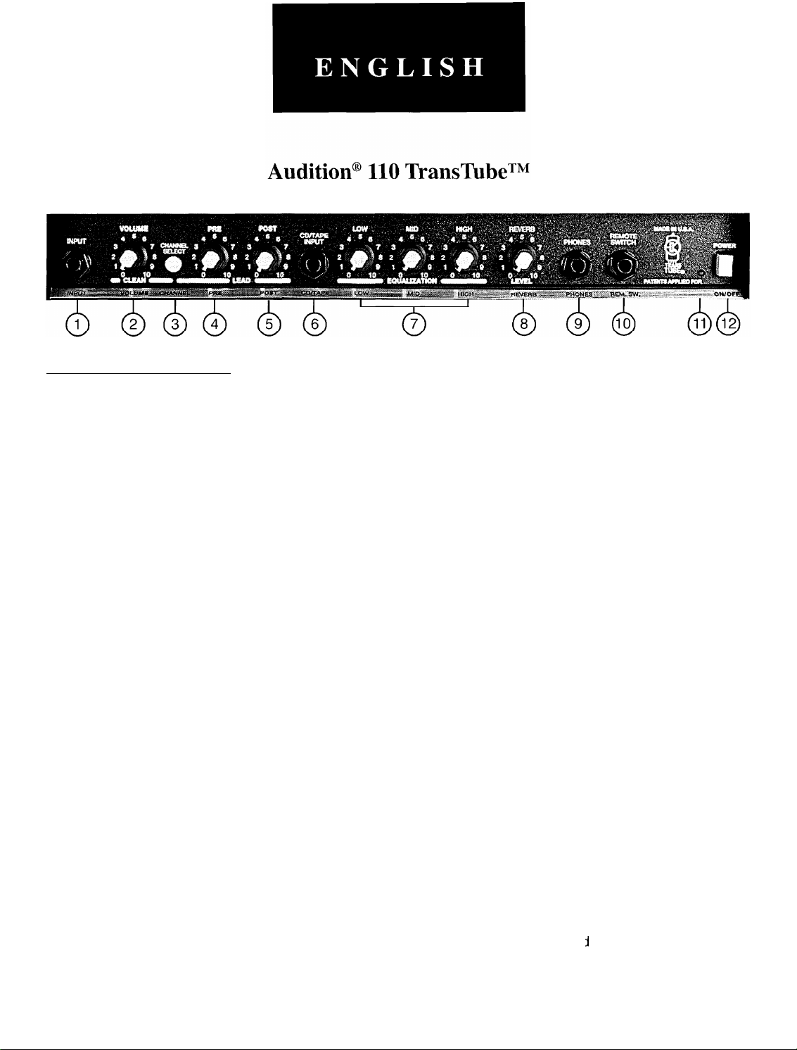
FRONT PANEL FEATURES
INPUT (1)
The input jack will accept signals from all types of guitar pickups.
VOLUME (2)
Controls the volume level of the Clean channel.
CHANNEL SELECT SWITCH (3)
Allows selection of the Lead or Clean channel. The “in” position of the switch selects the Lead channel and
the “out” position selects Clean.
NOTE: Channels may also be selected with the remote footswitch. If remote selection is desired, the channel switch must be in the “in” (Lead) position.
PRE GAIN (4)
Controls the input gain of the Lead channel.
POST GAIN (5)
Controls the overall volume level of the Lead channel. The final level adjustment should be made after the
desired sound has been achieved.
CD/TAPE INPUT (6)
The CD/Tape input can be used to route the Headphone Out signal of a CD player, tape player, etc. into the
CD/Tape input. Connect the CD or tape headphone output using a shielded cable to the CD/Tape input jack.
This signal is mixed with the guitar signal but is not affected by the EQ.
LOW, MID, & HIGH EQ (7)
Passive tone controls that regulate the low, mid, and high frequencies of both the Clean and Lead channels.
REVERB (8)
Controls the overall reverb level.
HEADPHONE JACK (9)
This stereo jack allows signal to flow to both sides of any stereo headset for private
headset may be used, but is not recommended.
REMOTE SWITCH (10)
Provided for the connection of the optional remote footswitch. The footswitch is usec
Clean channel.
NOTE: The Channel Select switch must be in the “in” position in order for the footswitch to function properly.
listening. A monaural
1
to select the Lead or
3
Page 4
POWER LED (11)
Illuminates when AC power is being supplied to the amp.
POWER SWITCH (12)
Depress the switch to the “on” position. The red LED will illuminate indicating that power is being supplied to
the unit.
WARNING: THIS UNIT IS CONNECTED TO THE MAINS POWER, EVEN IF THE POWER SWITCH IS
OFF.
A
CAUTION: TO PREVENT ELECTRIC SHOCK, MATCH WIDE BLADE OF PLUG TO WIDE SLOT AND
FULLY INSERT.
A
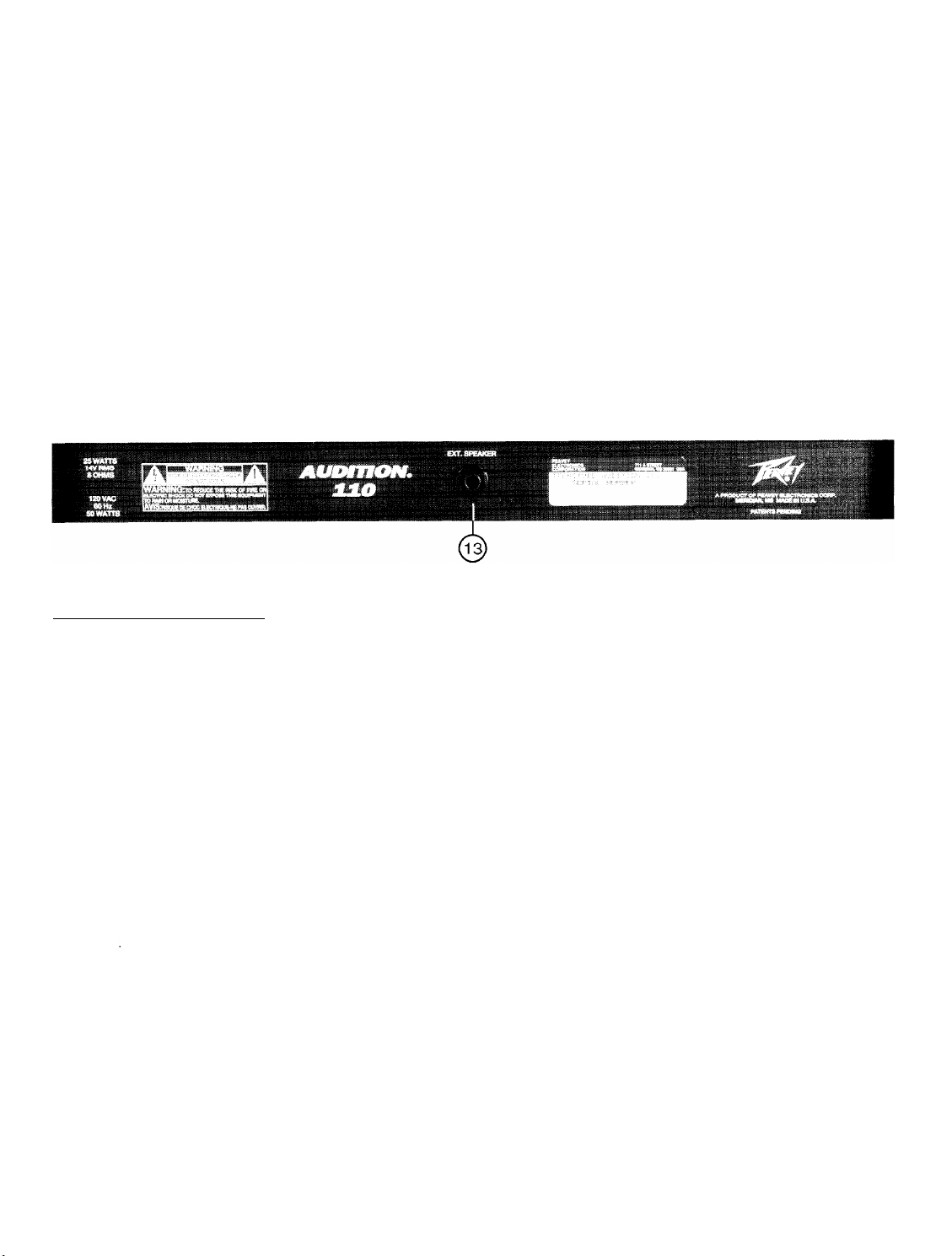
BACK PANEL FEATURES
EXTERNAL SPEAKER JACK (13)
Provided for connection of external speaker cabinet. Minimum total impedance is 8 ohms.
Disconnects internal speaker when used.
A
Page 5
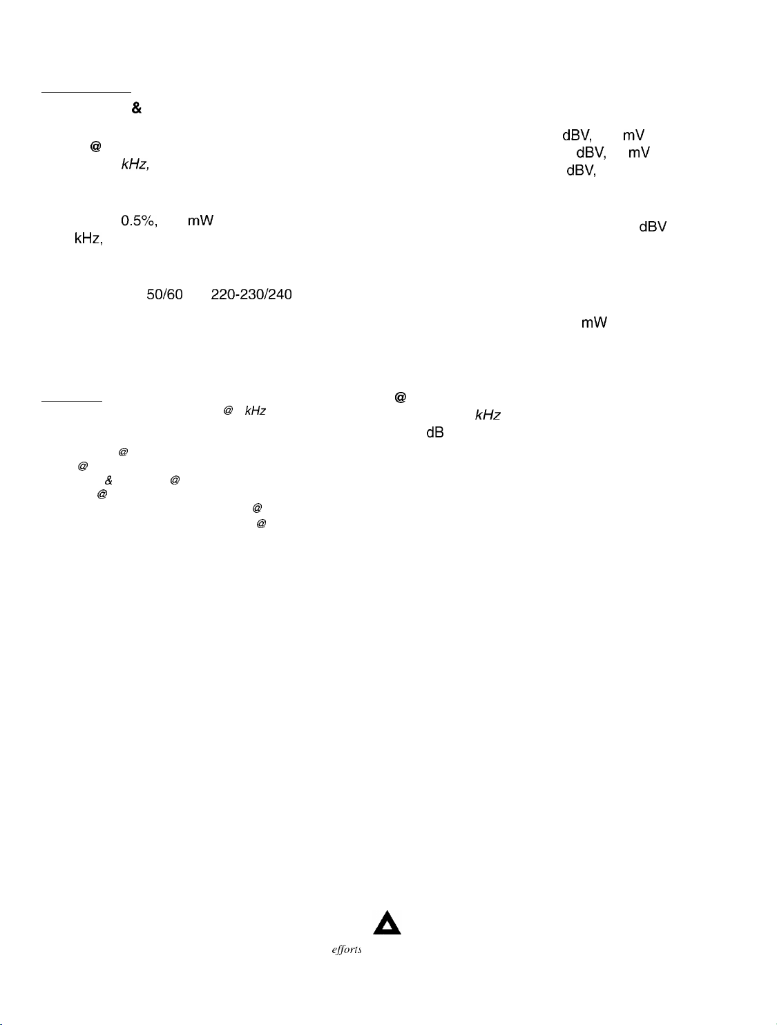
SPECIFICATIONS
POWER AMP
Rated Power 81 Load:
25 W RMS into 8 ohms
Power @ Clipping: (typically)
(5% THD, 1
kHz,
120 V AC line)
25 W RMS into 8 ohms
Total Harmonic Distortion:
Less than 0.5%, 100 mW to IO W RMS, 60 Hz to
10
kHz,
4 ohms (typically below 0.2%)
Power Consumption:
Domestic: 50 W, 60 Hz, 120 V AC
Export: 50 W, 50/60 Hz, 220-230/240 V AC
Dimensions and Weight:
16.125” H x 18.125” W x 9.25” D
19.6 Ibs.
PREAMP
The following specs are measured @ 2 kHz with the controls
preset as follows:
Channel Select Normal (out)
Low& High @ 10
Mid @ 0
Pre Gain 6: Post Gain @ 10
Reverb 63 0
Nominal Levels are with Normal Gain @ 5
Minimum Levels are with Normal Gain @ 10
Preamp Input:
(normal channel)
Impedance: High-Z, 1 M ohm
-6
dBV,
-23
dBV,
dBV,
500 mV RMS
70 mV RMS
1 V RMS
Nominal Input Level:
Minimum Input Level:
Maximum Input Level: 0
CD/Tape Input:
Input Impedance: 100 K ohms
Nominal Input Level: 0.5 V RMS, -6 dBV
(Stereo jack designed for use with stereo headphone outputs on
CD/Tape players)
Headphone Output:
Load Impedance: 4 ohms or greater
Nominal Power Output: 20 mW into 4 ohms
(Stereo jack, monaural signal, disconnects internal speaker when
phone plug is inserted)
System Hum & Noise
@
Nominal Input Level:
(20 Hz to 20
kHz
unweighted)
62 dB below rated power
Equalization:
Special low, mid, & high passive type EQ
Due to our efforts for constant improvements,
and
specijicatiom listed herein are subject to change
5
without
Page 6

r
s
$
a
Z
-
6
Page 7

METAL
TONE SETTINGS
ADJUST TO
TASTE
MEDIUM DISTORTION
VOLUME
0
CLEAN - LEAD
I
ADJUST TO
0
TASTE
PRE POST
COUNTRY LEAD
VOLUME
PRE POST
- LEAD -
EQtAL&ON
LOW
*;@;
B
*;@-)
0
;+j;
EQliALIZAi:ON
LOW MID
g!+j;
10
EQiALIZA+iON
MID
-
;g;*
0 10
-
f$
0 10
-
LEVEL
ADJUST TO
TASTE
PATENTS APPLIED FOR
LEVEL
ADJUST TO
TASTE
PATENTS APPLIED FOR
LEVEL
ADJUST TO
TASTE
TECHNOLOGY
PATENTS
Aflf’LIED
FOR
7
ADJUST TO
TASTE
Page 8

Consulte 10s diagramas de1 panel
delantero en la
CARACTERkTlCAS
INPUT (Entrada) (1)
El enchufe hembra de entrada acepta todo tipo de sehales provenientes de captadoras de instrumentos
electricos de cuerda.
VOLUME (Volumen) (2)
Controla el nivel de volumen del canal “clean” (limpio).
CHANNEL SELECT SWITCH (Interruptor para selection clel canal) (3)
Permite la
“lead” y la position hacia fuera selecciona el canal “clean”.
NOTA: La selection del canal puede lograrse tambien con el pedal interruptor de control remoto. Si se
desea hater
PRE GAIN (Ganancia previa) (4)
Controla la ganancia de entrada del canal solista.
POST GAIN (Ganancia posterior) (5)
Controla el volumen general del canal solista. El ajuste final de nivel debe hacerse despues de que se haya
obtenido el sonido deseado.
selection
selection
DEL TABLERO FRONTAL
del canal “lead” (solista) o “clean” (limpio). La
con control remoto, el interruptor de canal debe estar en la
seccih
de
inglCs
de este manual.
position
hacia dentro selecciona el canal
position
dentro (“lead”).
CD/TAPE INPUT (Entrada para CD/Cinta) (6)
La entrada
compactos, reproductor de cassettes, etc. hacia la entrada
auriculares del reproductor de discos compactos o de cassettes al enchufe de entrada para
medio de un cable blindado. Esta senal se mezcla con la sehal de la guitarra, pero no es afectada por la
igualacion (EC).
LOW, MID, & HIGH EQ (Ecualizador de frecuencias graves, medias, y agudas) (7)
Controles de tono pasivo que regulan las frecuencias graves, medias, y agudas del canal solista y limpio.
REVERB (Reverberation) (8)
Controla el nivel general de la reverb eracion.
HEADPHONE JACK (Enchufe hembra
Este enchufe hembra estereofonico permite a la senal fluir a ambos lados de cualquier audifono
estereofonico. Se puede usar un audifono monofonico, pero no es recomendable.
REMOTE SWITCH (Interruptor remoto) (10)
Se proporciona para la conexion del pedal interruptor remoto optional. El pedal interruptor se
seleccionar
NOTE: El Interruptor para seleccionar del canal debe estar en la
para CDkinta
10s
canales “lead” (solista) o “clean” (limpio).
puede usarse
para
encaminar la
para
audifonos) (9)
8
senal
de salida de un reproductor de discos
para CDkinta.
position
Conecte la salida de
“hacia dentro”.
10s
CDkinta
usa para
por
Page 9

POWER LED (LED indicador de corriente) (11)
Se ilumina cuando el amplificador recibe corriente alterna.
POWER SWITCH (Interruptor de corriente) (12)
Oprima el interruptor a la
indicando que la unidad esta recibiendo corriento alterna.
ADVERTENCIA: ESTA UNIDAD QUEDA CONECTADA A LA FUENTE DE CORRIENTE PRINCIPAL,
AUNQUE EL INTERRUPTOR DE POTENCIA ESTk APAGADO.
position
“hacia dentro” (encendido). La luz roja del pilot0 (indicador) se encendera
A
PRECAUCION: PARA EVITAR CORRIENTAZOS
EL LAD0 ANCHO DEL ENCHUFE MACHO CON LA RANURA ANCHA DE LA
INSERTAR COMPLETAMENTE AL FONDO.
ELkTRICOS,
ES NECESARIO HACER COINCIDIR
A
CARACTERjSTlCAS
EXTERNAL SPEAKER JACK (Enchufe hembra de altavoz externo) (13)
DEL TABLERO TRASERO
Se suministra para la conexion de bafles externos. La impedancia total minima es de
8 ohms.
A
TOMA
E
Page 10

Veuillez-vows
rkfker
au “front panel art”
situ6 dans la section en langue anglaise de ce manuel.
CARACTERISTIQUES
INPUT (Entree) (1)
Cette prise d’entree accepte les signaux de tous les types de micros (“pickups”) de guitare.
VOLUME (2)
Controle le niveau de volume du canal “Clean”.
CHANNEL SELECT SWITCH (Sklecteur de canal) (3)
Permet de selectionner les canaux “Lead” ou “Clean”. La position “In” du selecteur correspond au canal
“Lead”. La position “Out” selectionne le canal “Clean”.
REMARQUE: La selection des canaux peut aussi se faire a distance est desiree, le selecteur “Channel
Select Switch” doit etre en position “In” (“Lead”).
PRE GAIN (4)
Contrcle le gain d’entree du canal “Lead”.
POST GAIN (5)
Commande le volume general du canal “Lead”. Le reglage final de niveau doit etre
obtenu la sonorite desiree a I’aide des autres reglages.
CD/TAPE INPUT (Entree CD/Cassette) (6)
L’entree CD/cassette peut etre utilisee pour y acheminer le signal de sortie du casque d’ecoute d’un lecteur
de CD, d’un lecteur de cassettes, etc. Brancher la sortie de ce casque d’ecoute dans la fiche d’entree CD/
cassette a I’aide d’un cable blind& Ce signal est mixe avec le signal de la guitare mais
I’egaliseur.
DU PANNEAU AVANT
effect&
nest
apres avoir
pas affecte par
LOW, MID, & HIGH EQ (Egalisation graves, moyennes et
Reglages de tonalite passifs reglant les frequences graves, moyennes et aigues des canaux “Lead” et
“Clean”.
REVERB
Controle le niveau de volume global de la reverberation.
HEADPHONE JACK (Prise pour casque
Ce jack stereo envoie le signal aux deux
monophonique est possible mais non recommande.
REMOTE SWITCH (Interrupteur pour commande ti distance) (10)
Sert a brancher une pedale-interrupteur (en option) pour controle a distance. L’interrupteur au pied peut etre
utilise pour selectionner les canaux “Lead” ou “Clean”.
NOTE: Le Selecteur de Canal doit etre en position “In”.
POWER LED (DEL temoin de mise sous tension) (11)
S’allume lorsque I’ampli recoit I’alimentation CA.
(Rkverbhation)
(8)
d’koute)
cot&s
de tout casque d’ecoute stereo. L’usage d’un casque
(9)
aiguh)
(7)
Page 11

POWER SWITCH (Interrupteur d’alimentation) (12)
Mettre I’interrupteur en position “On”. La lampe tkmoin rouge (DEL) s’illumine indiquant que I’appareil est
aliment6 en courant.
AVERTISSEMENT: CET APPAREIL EST RELIE A L’ALIMENTATION PRINCIPALE MEme SI
L’INTERRUPTEUR D’ALIMENTATION EST EN POSITION “OFF”.
A
ATTENT IO N : POUR EVITER LES CHOCS ELECTRIQUES, INTRODUIRE LA LAME LA PLUS LARG E
DE LA FICHE DANS LA BORNE CORRESPONDANTE DE LA PRISE ET POUSSER
JUSQU’AU FOND.
A
CARACTERISTIQUES DU PANNEAU
EXTERNAL SPEAKER JACK (Prise pour haut-parleur externe) (13)
Sortie pour branchement d’une enceinte de haut-parleur @Parke. L’impedance totale
resultant doit
&tre
au minimum 8 ohms.
ARRIERE
A
11
Page 12

Siehe Diagramm der Frontplatte im englischen Teil des Handbuchs.
BESCHREIBUNG DER FRONTPLATTE
INPUT (Eingang) (1)
Diese Eingangsbuchse verarbeitet Signale von Gitarrentonabnehmern aller Art.
VOLUME (Lautstarke) (2)
Regelt die Lautstarke des Clean-kanals.
CHANNEL SELECT SWITCH (Kanal-Wahl-Schalter) (3)
Erlaubt die Auswahl des Lead- oder des Clean-Kanals. Die “In-Position des Schalters wahlt den LeadKanal, die “Out’‘-Position den Clean-Kanal an.
MERKE: Kanalwahl kann such mittels dem FernbedienungsfuOschalter ausgefuhrt werden. Dazu
“Channel”-Schalter sich in der “in” (Lead) Position befinden.
PRE GAIN (4)
Regelt die Eingangsempfindlichkeit des Lead-Kanal.
POST GAIN (5)
Kontrolliert den gesamten Lautstarke-pegel des Hauptkanals (Mastervolumen). Die endgultige
Lautstarkeregelung sollte vorgenommen werden, nachdem der gewanschte Sound eingestellt ist.
muf3
der
CD/TAPE INPUT (CD/Tape-Eingang) (6)
LJber
den CD/Tape-Eingang konnen die Kopfhdrer-Ausgangssignale eines CD-Players, Tapedecks, etc.
eingespeist werden. Den CD- oder Tapedeck-Kopfhorerausgang mit einem abgeschirmten Kabel mit dem
CD/Tape-Eingang verbinden. Das Signal wird mit dem Gitarrensignal gemischt, jedoch nicht durch den EQ
beeinfluf3t.
LOW, MID, & HIGH EQ (Tiefen, mittleren und hohen EQ) (7)
Diesepassiven Klangregler regeln die tiefen, mittleren und hohen Frequenzen des Clean- und Lead-Kanals.
REVERB (8)
Regler fur den Gesamtanteil des Halls.
HEADPHONE JACK (Kopfhijrer-Anschluss) (9)
Dieser Stereo-Jack-Anschluss ubertragt das Signal auf beide Kopfhorer-Muscheln. Ein Mono-Kopfhorer
kann zwar verwendet werden, wird jedoch nicht empfohlen.
REMOTE SWITCH (Fern
Zum Anschlul3 des zusatzlich erhaltlichen FuDschalters. Hiermit werden die Lead- und Clean-Kanal.
NOTE: Der Kanal-Wahl-Schalter
fuf3schalter)
muf3
(10)
sich in der “in’‘-Position.
12
Page 13

POWER LED (LED fur die Netzschalter) (11)
Zeigt die eingeschaltete Netzspannung an.
POWER SWITCH (Netzschalter) (12)
Bringen Sie den Schalter auf die ON-Position. Die rote Kontrollampe (LED) leuchtet und zeigt an, da0 das
Get-St
eingeschaltet ist.
WARNUNG: Diese Einheit ist immer mit dem Stromnetz verbunden such wenn der Netzschalter
ausgeschaltet ist.
A
VORSICHT: Urn einen elektrischen Schlag zu vermeiden, den Stecker immer komplett in die
Steckdose einfuhren.
A
13
0
BESCHREIBUNG DER RUCKPLATTE
EXTERNAL SPEAKER JACK (Buchen fur externe Lautsprecher) (13)
AnschluObuchse
betrAgt 8 Ohm.
fiir
einen zus&tzlichen Lautsprecher. Die minimale Gesamtimpedanz
A
13
Page 14

THIS LIMITED WARRANTY VALID ONLY WHEN PURCHASED AND REGISTERED IN THE UNITED STATES OR CANADA. ALL EXPORTED PRODUCTS
ARE SUBJECT TO WARRANTY AND SERVICES TO BE SPECIFIED AND PROVIDED BY THE AUTHORIZED DISTRIBUTOR FOR EACH COUNTRY.
Ces clauses de garantie ne sont vaiables qu’aux Etats-Unis et au Canada. Dans tour les autres pays, les clauses de garantie et de maintenance sont
fixees par le distributeur national et assuree par lul seion la legislation envigueur.
Produkte sind der Garantie und dem Service des lmporteurs des jewelligen Landes unterwotfen.
product0 es comprado en E.U. continentales o en Canada. Todos
servicio uue cada distribuidor autorizado determine v ofrezca en
10s
prbductos que
10s
diferentes Daises.
l l
Diese Garantie ist nur in den USA and Kanada gultig. Alle Export-
Sean
l l
Esta garantia es valida solamente cuando el
comprados en el extranjero, estan sujetos a las garantias y
PEAVEY ONE-YEAR LIMITED
WARRANTY/REMEDY
PEAVEY ELECTRONICS CORPORATION (“PEAVEY”) warrants this product, EXCEPT for covers, footswitches, patchcords, tubes and meters, to be free from
defects in material and workmanship for a period of one (1) year from date of purchase, PROVIDED, however, that this limited warranty is extended only to the
origrnal
retail purchaser and is subject to the conditions, exclusrons, and limitations hereinafter set forth:
PEAVEY 90-DAY LIMITED WARRANTY ON TUBES AND METERS
If this product contains tubes or meters, Peavey warrants the tubes or meters contarned in the product to be free from defects in material and workmanshrp for
a period of ninety (90) days from date of purchase; PROVIDED, however, that
subjecttothe conditions, exclusions,
and limitations hereinafter set forth.
CONDITIONS, EXCLUSIONS, AND
thus
limited warranty is extended only to the original retail purchaser and
LIMITATIONS
OF
LIMITED
WARRANTIES
IS
also
These limited warranties shall be void and of no effect, if:
a.
The first purchase of the product is for the purpose of resale: or
b.
The original retail purchase is not made from an AUTHORIZED PEAVEY DEALER; or
c.
The product has been damaged by accident or unreasonable use, neglect, improper service or maintenance, or other causes not arislng out of defects in
material or workmanship; or
d.
The serial number affixed to the product is altered, defaced, or removed.
In the event of a defect in material and/or workmanshrp covered by this limited warranty, Peavey will:
a.
In the case of tubes or meters, replace the defective component without charge.
b.
In other covered cases (i.e., cases involving anything other than covers, footswitches, patchcords, tubes or meters), repair the defect in material or
.
workmanshrp or replace the product, at Peavey’s option; and provided, however, that, In any case, all costs of shipping, if necessary, are paid by you, the
purchaser.
THE WARRANTY REGISTRATION CARD SHOULD BE ACCURATELY COMPLETED AND MAILED TO AND RECEIVED BY PEAVEY WITHIN FOURTEEN (14)
DAYS FROM THE DATE OF YOUR PURCHASE.
In order to obtain service under these warranties, you must:
a.
Brina the defective item to anv PEAVEY AUTHORIZED DEALER or AUTHORIZED PEAVEY SERVICE CENTER and present therewith the ORIGINAL
PRCOF
OF PURCHASE supplied to you by the
AUTHORIZED PEAVEY DEALER In connection with
your purchase from him of this product.
If the DEALER or SERVICE CENTER is unable to provide the necessary warranty service you will be directed to the nearest other PEAVEY AUTHORIZED
DEALER or AUTHORIZED PEAVEY SERVICE CENTER which can
b. Ship the defective item, prepaid, to:
PEAVEY ELECTRONICS CORPORATION
provide such service.
International Service Center
326 Hwv. 11 & 80 East
MERIDIAN, MS 39301
including therewith a complete, detailed description of
address. Upon Peavey’s receipt of these items: If the
the problem, together
defect is remedial under these limited warranties and the other terms and conditions expressed herein
have been complied with, Peavey will provide the necessary warranty service to repair or replace the product and
with
a legible copy of the original PROOF OF PURCHASE and a complete return
will
return it, FREIGHT COLLECT, to you,
the purchaser.
Peavey’s liability to the purchaser for damages from any cause whatsoever and regardless of the form of action, including negligence, is limited to the actual
damages up to the greater of $500.00 or an amount equal to the purchase price of the product that caused the damage or that
IS
the subject of or is directly related
to the cause of action. Such purchase price will be that in effect for the specific product when the cause of action arose. This limitation of liability will not apply to
claims for personal injury or damage to real property or tangible personal property allegedly caused by Peavey’s negligence. Peavey does not assume liability for
personal injury or property damage arising out of or caused by a non-Peavey alteration or attachment, nor does Peavey assume any responsibility for damage to
interconnected non-Peavey equipment that may result from the normal functioning and maintenance of the Peavey equipment.
UNDER NO CIRCUMSTANCES WILL PEAVEY BE LIABLE FOR ANY LOST PROFITS, LOST SAVINGS, ANY INCIDENTAL DAMAGES, OR ANY
CONSEQUENTIAL DAMAGES ARISING OUT OF THE USE OR INABILITY TO USE THE PRODUCT, EVEN IF PEAVEY HAS BEEN ADVISED OF THE
POSSIBILITY OF SUCH DAMAGES.
THESE LIMITED WARRANTIES ARE IN LIEU OF ANY AND ALL WARRANTIES, EXPRESSED OR IMPLIED, INCLUDING, BUT NOT LIMITED TO, THE
IMPLIED WARRANTIES OF MERCHANTABILITY AND FITNESS FOR A PARTICULAR USE: PROVIDED, HOWEVER, THAT IF THE OTHER TERMS AND
CONDITIONS NECESSARY TO THE EXISTENCE OF THE EXPRESSED, LIMITED WARRANTIES, AS HEREINABOVE STATED, HAVE BEEN COMPLIED
WITH, IMPLIED WARRANTIES ARE NOT DISCLAIMED DURING THE APPLICABLE ONE-YEAR OR NINETY-DAY PERIOD FROM DATE OF PURCHASE OF
THIS PRODUCT.
SOME STATES DO NOT ALLOW LIMITATION ON HOW LONG AN IMPLIED WARRANTY LASTS, OR THE EXCLUSION OR LIMITATION OF INCIDENTAL
OR CONSEQUENTIAL DAMAGES, SO THE ABOVE LIMITATIONS OR EXCLUSIONS MAY NOT APPLY TO YOU. THESE LIMITED WARRANTIES GIVE YOU
SPECIFIC LEGAL RIGHTS, AND YOU MAY ALSO HAVE OTHER RIGHTS WHICH MAY VARY FROM STATE TO STATE.
THESE LIMITED WARRANTIES ARE THE ONLY EXPRESSED WARRANTIES ON THIS PRODUCT, AND NO OTHER STATEMENT, REPRESENTATION,
WARRANTY, OR AGREEMENT BY ANY PERSON SHALL BE VALID OR BINDING UPON PEAVEY.
In the event of any
then such
modrfrcation,
modrficatron
or disclaimer of expressed or implied warranties, or any limitation of remedies, contained herein conflicts with applicable
disclaimer or limitation, as the case may be, shall be deemed to be modified to the extent necessary to comply with such law.
law,
Your remedies for breach of these warranties are limited to-those remedies provrded herein and Peavey Electronics Corporation gives this limited warranty only
with respect to equipment purchased in the United States of America.
1,
Marl the completed WARRANTY REGISTRATION CARD to:
INSTRUCTIONS - WARRANTY REGISTRATION CARD
PEAVEY ELECTRONICS CORPORATION
POST OFFICE BOX 2898
MERIDIAN, MISSISSIPPI 39302-2898
a. Keep the PROOF OF PURCHASE. In the event warranty service is required during the warranty period, you will need this document. There will be no
Identification card issued by Peavey Electronics Corporation.
2.
IMPORTANCE OF WARRANTY REGISTRATION CARDS AND
NOTIFICATION OF CHANGESOFADDRESSES:
a. Completion and mailing of WARRANTY REGISTRATION CARDS - Should notification become necessary for any condition that may require correctron,
the REGISTRATION CARD will help ensure that you are contacted and properly notified.
b. Notice of address changes - If you move from the address shown on the WARRANTY REGISTRATION CARD, you should notify Peavey of the change of
address so as to facilitate your receipt of any bulletins or other forms of notification which may become necessary
in
connectron with any condition that may
require dissemination of information or correction.
3.
You may contact Peavey directly by telephoning (601) 483-5365.
14
Page 15

IMPORTANT SAFETY INSTRUCTIONS
WARNING: When using electric products, basic cautions should always be followed, including the following.
1.
Read all safety and operating instructions before using this product.
2.
All safety and operating instructions should be retained for future reference.
3.
Obey all cautions in the operating instructions and on the back of the unit.
All operating instructions should be followed.
4.
This product should not be used near water, i.e., a bathtub, sink, swimming pool, wet basement, etc.
5.
6.
This product should be located so that its position does not interfere with its proper ventilation. It should not be placed flat against a
wall or placed in a built-in enclosure that will impede the flow of cooling air.
This product should not be placed near a source of heat such as a stove, radiator, or another heat producing amplifier.
7.
Connect only to a power supply of the type marked on the unit adjacent to the power supply cord.
8.
Never break off the ground pin on the power supply cord. For more information on grounding, write for our free booklet ‘Shock
9.
Hazard and Grounding.”
Power supply cords should always be handled carefully. Never walk or place equipment on power supply cords. Periodically check
10.
cords for cuts or signs of stress, especially at the plug and the point where the cord exits the unit.
1 I.
The power supply cord should be unplugged when the unit is to be unused for long periods of time.
12.
If this product is to be mounted in an equipment rack, rear support should be provided.
Metal parts can be cleaned with a damp rag. The vinyl covering used on some units can be cleaned with a damp rag or an ammonia-
13.
based household cleaner if necessary. Disconnect unit from power supply before cleaning.
14.
Care should be taken so that objects do not fall and liquids are not spilled into the unit through the ventilation holes or any other
openings.
This unit should be checked by a qualified service technician if:
15.
a.
The power supply cord or plug has been damaged.
b.
Anything has fallen or been spilled into the unit.
The unit does not operate correctly.
C.
d.
The unit has been dropped or the enclosure damaged.
16.
The user should not attempt to service this equipment. All service work should be done by a qualified service technician.
This product should be used only with a cart or stand that is recommended by Peavey Electronics.
17.
Exposure to extremely high noise levels may cause a permanent hearing loss. Individuals vary considerably in susceptibility to noise
18.
induced hearing loss, but nearly everyone will lose some hearing if exposed to sufficiently intense noise for a sufficient time.
The U.S. Government’s Occupational Safety and Health Administration (OSHA) has specified the following permissible noise level
exposures.
Duration Per Day In Hours Sound Level
8
6
4
3
2
1
112
1
112
1/4 or less
dBA,
Slow Response
90
92
95
97
100
102
105
I IO
115
15
Page 16

01995
Peavey Electronics Corporation
711 A Street / Meridian, MS 39301 / U.S.A. / (601) 483-5365 / Fax 486-1278
#80302353
Printed in U.S.A.
I/96
 Loading...