

Page 1
6505® MICRO™
Amplifier
Operating
Manual
www.peavey.com
Page 2

FCC/ICES Compliancy Statement
This device complies with Part 15 of the FCC rules and Industry Canada license-exempt RSS Standard(s). Operation is
subject to the following two conditions: (1) this device may not cause harmful interference, and (2) this device must
accept any interference received, that may cause undesired operation.
Le présent appareil est conforme aux CNR d’lndustrie Canada applicables aux appareils radio exempts de
licence. L’exploitation est autorisée aux deux conditions suivantes: (1) I’appareil ne doit pas produire de
brouillage, et (2) I’utilisateur de I’appareil doit accepter tout brouillage radioélectrique subi, même si le
brouillage est susceptible d’en compromettre le fonctionnement.
Warning: Changes or modifications to the equipment not approved by Peavey Electronics Corp. can void the
user’s authority to use the equipment.
Note – This equipment has been tested and found to comply with the limits for a Class B digital device,
pursuant to Part 15 of the FCC Rules. These limits are designed to provide reasonable protection against
harmful interference in a residential installation. This equipment generates, uses, and can radiate radio
frequency energy and, if not installed and used in accordance with the instructions, may cause harmful
interference to radio communications. However, there is no guarantee that interference will not occur in a
particular installation. If this equipment does cause harmful interference to radio or television reception,
which can be determined by turning the equipment off and on, the user is encouraged to try and correct the
interference by one or more of the following measures.
• Reorient or relocate the receiving antenna.
• Increase the separation between the equipment and receiver.
• Connect the equipment into an outlet on a circuit different from that to which the receiver is
connected.
• Consult the dealer or an experienced radio/TV technician for help.
Caution
The equipment complies with FCC radiation exposure limits set forth for an uncontrolled
environment.
Page 3

ENGLISH
6505® MICRO™
Tube Amplifier
Congratulations on your purchase of the all-new 6505 MICRO Head! is miniscule little beast harnesses the
character and “crunch” and “lead” tones of it’s much larger all-tube siblings in a super-small and convenient
package capable of up to a mighty 20 Watts (4 Ohms). A single 12AX7 tube compliments the gain structure in
the most critical stages. is little guy sounds increasingly amazing and familiar on larger cabinets with more
premium drivers, such as the 112-6, 212-6, and the legendary 6505 412 cabs. e minimalist controls and extremely robust construction make this a must-have “Swiss army knife” tool for live and recording use. Use the
headphone jack & aux input for practice, connect the eects send to the input of a larger amp to use it as a “6505
preamp driver”, great for quick and easy “re-amping”, and any number of applications that you can dream up.
Read this manual thoroughly before use, keep your volume level in check and enjoy!
Features:
* 20W (RMS) into 4 Ohms
* 12AX7/ECC83 Preamp Tube
* Speaker Output
* Crunch/Lead Switch
* Single Knob EQ to morph through popular 6505 settings
* Auxiliary Input
* Buered Eects Loop
* Bulletproof Metal Enclosure
VENTILATION: For proper ventilation, allow 24” clearance from nearest combustible surface.
Page 4

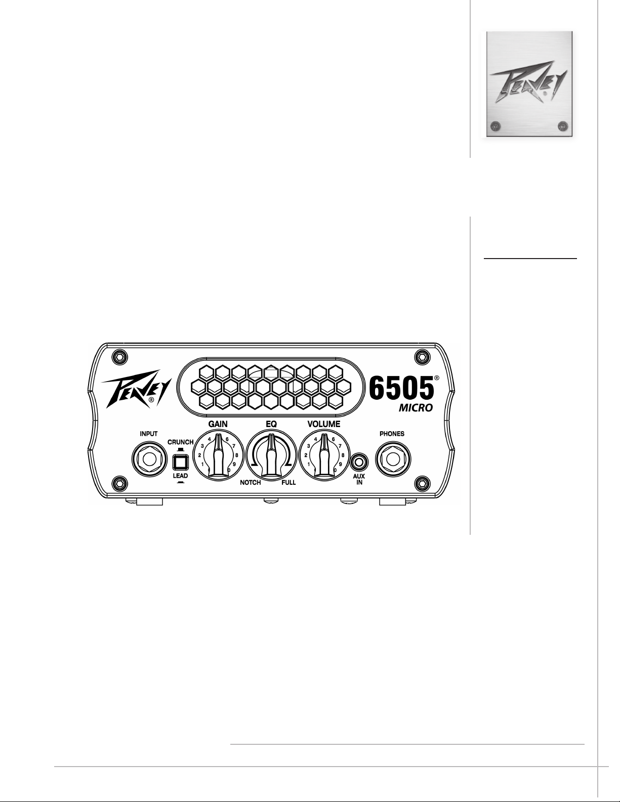
Front Panel
1 2 3 4 5 6 7
INPUT - Used for most electric guitars. Plug your guitar into this jack using a high-quality shielded instru-
1
ment cable for low noise.
CRUNCH/LEAD - is switch toggles the preamp from CRUNCH to LEAD gain modes. CRUNCH is typical
2
of the “crunch” setting on the original 6505 rhythm channel with the bright boost included and LEAD is typical of the classic 6505 high-gain lead sound.
3
GAIN - is controls the input level of the amplier, as it feeds the rst JFET gain stage. Clockwise adjustment
of this control will result in a hotter and more “responsive” signal to the amplier input circuit.
4
EQ - is control “morphs” from a 6505 “notched” 3-band EQ setting (10-0-7) in the NOTCH position, to
the more common “7-7-7” setting at about halfway, and up to full on midrange (10-10-10) at its full clockwise
position.
5
VOLUME - is control adjusts the overall volume of the preamp as it is fed into the power amp section.
AUX IN - is 1/8” stereo input is provided to insert a full-range audio source into the signal chain, such as a
6
portable MP3 player or other media device.
PHONES - is stereo ¼” jack is provided to drive most common studio headphones.
7
Page 5

Rear Panel
8 9 10 11
SPEAKER - is ¼” mono jack is provided for connection of an external speaker cabinet. Minimum load im-
8
pedance is 4 Ohms.
EFFECTS LOOP SEND and EFFECTS LOOP RETURN
9
1/4” output jack for supplying signals to external eects or signal processing equipment and 1/4” input for returning signals from external eects or signal processing equipment.
10
DC SUPPLY - is jack is provided for connection of the included +30VDC power supply. NOTE: PLEASE
USE ONLY THE SUPPLIED POWER ADAPTOR (Peavey #30908151) TO POWER YOUR 6505 MICRO.
11
POWER - is switch applies or removes DC power to the internal circuitry.
Product Specifications
Power Amplier Section:
Rated Power & Load: 20W(rms) into 4 Ohms; 15W(rms) into 8 Ohms; 10W(rms) into 16 Ohms
DC Supply (included): +30VDC @ 1ADC (positive tip); Peavey part #30908151
Preamp Section:
Specs are measured @ 1kHz with all controls set halfway (12 o’clock) on CRUNCH setting
Input:
Impedance: 1M Ohms; Nominal Input Level: -20dBV, 100mV(rms)
Eects Loop Send:
Load Impedance: 10k Ohms or greater; Nominal Output Level: 0dBV, 1.0V(rms)
Eects Loop Return:
Impedance: 1M Ohms; Designed Input Level: 0dBV, 1.0V(rms)
(Switching jack provides preamp output to power amp input connection when not used)
Aux Input:
Nominal Input Level: 0dBV, 1.0V(rms)
Dimensions & Weight:
5.2” (132mm) L x 7.0” (178mm) W x 3.2” (82mm) H;
2.5 lbs (1.13 kg)
NOTE: Specications are subject to change without notice.
Page 6

Logo referenced in Directive 2002/96/EC Annex IV
The bar is the symbol for marking of new waste and
13 August 2005
www.peavey.com
Warranty registration and information for U.S. customers available online at
www.peavey.com/warranty
or use the QR tag below
Features and specications subject to change without notice.
Peavey Electronics Corporation 5022 Hartley Peavey Drive Meridian, MS 39305 (601) 483-5365 FAX (601) 486-1278
(OJ(L)37/38,13.02.03 and defined in EN 50419: 2005
is applied only to equipment manufactured after
 Loading...