

Page 1
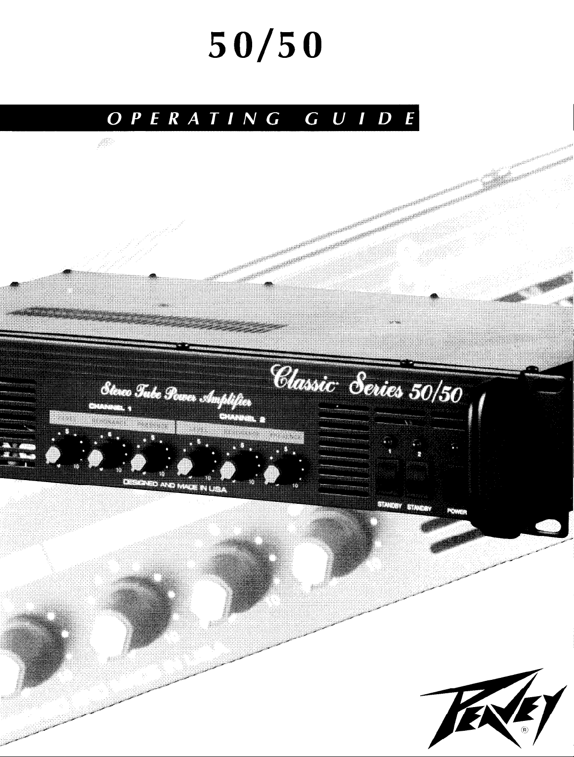
CLASSIC”
ALL TUBE POWER AMP
SO/50
Page 2

A
A
CAUTION Risks of electrical shock - DO NOT OPEN
CAUTION To reduce the risk of electric shock, do not remove cover. No user serviceable parts inside. Refer
Servicing to qualified service personnel.
WARNING
using this appliance, read the operating guide for further warnings.
IA
A
PRECAUCION Riesgo de corrientazo - No abra.
PRECAUCION
pueda reparar. Deje
ADVERTENCIA
Antes de usar este aparato, lea mas advertencias en la guia de
Intended to alert the user to the presence of uninsulated “dangerous voltage” within the product’s enclosure
that may be of sufficient magnitude to constitute a risk of electric shock to persons.
Intended to alert the user to the presence of important operating and maintenance (servicing) instructions in the literature accompanying the product.
To prevent electrical shock or fire hazard, do not expose this appliance to rain or moisture. Before
Este simbolo tiene el proposito de alertar al usuario de la presencia de instrucciones importantes
sobre la operaci6n y mantenimiento en la literatura que viene con el producto.
Este simbolo tiene el proposito de alertar al usuario de la presencia de “(voltaje) peligroso” que no
tiene aislamiento dentro de la caja de1 product0 que puede tener una magnitud suficiente coma
para
constituir riesgo de corrientazo.
Para
disminuir el riesgo de corrientazo, no
todo
mantenimiento a 10s tecnicos calificados.
Para
evitar corrientazos o peligro de incendio, no deje expuesto a la lluvia o humedad este aparato.
abra
la cubierta. No hay piezas adentro que el usuario
operation.
A
A
ATTENTION Risques de choc electrique - NE PAS OUVRIR!
ATTENTION
aucune piece pouvant
AVERTISSEMENT
a la pluie ou a l’humidite. Avant d’utiliser cet appareil, liscz les avertissements supplementaires
guide d’utilisation.
A
A
VORSICHT Risiko - Elektrischer Schlag! Nicht
VORSICHT
sich keine Teile darin, die vom Anwender repariert werden
sonal durchfiihren lassen.
ACHTUNG
oder Feuchtigkeit ausgesetzt werden. Vor Inbetriebnahme unbedingt die Bedienungsanleitung lesen.
Ce symbole est utilise pour indiquer a l’utilisateur qu’il ou qu’elle trouvera d’importantes instructions
sur l’utilisation et l’entretien (service) de l’appareil dans la litterature accompagnant le produit.
Ce symbole est
isolee
dangereuse pouvant
Afin
Dieses Symbol sol1 den Benutzer auf wichtige Instruktionen in der Bedienungsanleitung aufmerksam
machen, die Handhabung und Wartung des Produkts betreffen.
Dieses Symbol sol1 den Anwender vor unisolierten gefahrlichen Spannungen innerhalb des Gehauses
warnen, die von Ausreichender
Urn das Risiko eines elektrischen Schlages zu vermeiden, nicht die Abdeckung enfernen. Es befinden
Urn einen elektrischen Schlag oder Feuergefahr zu vermeiden, sollte dieses Gerat nicht dem Regen
utilize’
pour indiquer a l’utilisateur la presence a l’interieur de ce produit de tension non-
etre
d’intensite suffisante pour constituer un risque de choc electrique.
de reduire le risque de choc electrique, ne pas enlever le couvercle. 11 ne se trouve a l’interieur
etre reparee
Afin
de prevenir les risques de decharge electrique ou de feu, n’exposez pas cet appareil
par l’utilisateur. Confier l’entretien a un personnel
Starke
sind, urn einen elektrischen Schlag verursachen zu
offnen!
konnten.
Reparaturen nur von qualifiziertem Fachper-
qualifie.
situ&
kiinnen.
dans le
2
Page 3

3
7 8 9
10
11
12
51
POWER SWITCH (1)
Depress the switch to the “On” position. The red pilot light (LED) will illuminate indicating power is being
supplied to the unit.
POWER LED (2)
Illuminates when AC power is being supplied to the amp.
CHANNEL 1 STANDBY SWITCH (3)
Allows channel 1 of amp to be placed in standby or active mode. In standby mode the tubes remain hot,
but the amplifier is not operational.
CHANNEL 1 STANDBY LED (4)
Illuminates when amp is on. Does not illuminate when on standby.
CHANNEL 2 STANDYBY SWITCH (5)
Allows channel 2 of amp to be placed in standby or active mode. In standby mode the tubes remain hot,
but the amplifier is not operational.
CHANNEL 2 STANDBY LED (6)
Illuminates when amp is on. Does not illuminate when on standby.
CHANNEL 1 LEVEL CONTROL (7)
Controls the output level of channel 1 when in stereo; controls the output in mono mode. Maximum output
level is obtained with the level control rotated fully in a clockwise direction.
RESONANCE CHANNEL 1 (8)
Used to fine tune speaker enclosure low frequency response by varying the damping factor of channel 1 at
low frequencies.
PRESENCE CHANNEL 1 (9)
Used to fine tune speaker enclosure high frequency response by varying the damping factor of channel 1 at
high frequencies.
CHANNEL 2 LEVEL CONTROL (10)
Controls the output level of channel 2 when in stereo mode. Maximum output level is obtained with the level
control rotated fully in a clockwise direction.
NOTE: Not operational when in mono mode.
Page 4
RESONANCE CHANNEL 2 (11)
Used to fine tune speaker enclosure low frequency response by varying the damping factor of channel 2 at
low frequencies.
NOTE: Not operational in mono mode.
PRESENCE CHANNEL 2
(12)
Used to fine tune speaker enclosure high frequency response by varying the damping factor of channel 2 at
high frequencies.
NOTE: Not operational in mono mode.
26
., ;:.
:
>;.:.,...:
.: .;,
MIIzIl
27
28
$gY&&f+ c&d
I\ PRW”CT”F
MERILIAN
sol!sci
EWE” ELtCTRcNCSMRP
MS
MADE
IN ” s *
PATENT
PENDlNG
17 18 20
& @gg;&:L$
-ee
-T
-g&*;;Y$&
16 -14'
,g;;
&
LE”,:”
I I
19 21 23
2?
@‘fg->4
DMECT
I;;, \ -l
q&L g-25
I
15
r13-
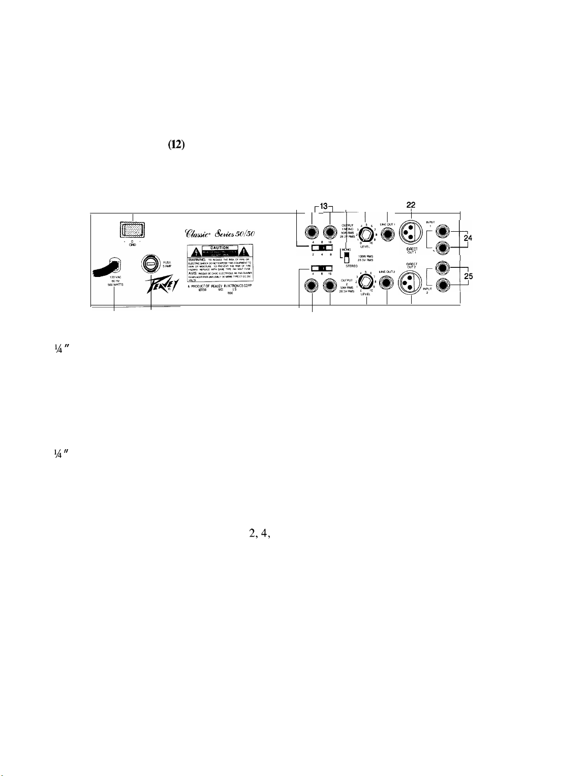
SPEAKER OUTPUTS CHANNEL 1 (13)
Two
r/4 ”
speaker outputs are provided. These jacks are in parallel. The impedance switch for channel 1 selects
the total impedance plugged into the channel 1 output.
NOTE: When switch (mono/stereo) is switched to stereo use the numbers 16, 8, and 4 that are above the
channel 1 impedance switch.
When switch (mono/stereo) is switched to mono use the numbers 8, 4, and 2 that are below the channel 1
impedance switch.
SPEAKER OUTPUTS CHANNEL 2 (14)
Two
‘/4 fl
speaker outputs are provided. These jacks are in parallel. The impedance switch for channel 2 selects
the total impedance plugged into the channel 2 output.
NOTE: Not used for mono operation.
IMPEDANCE SELECTOR CHANNEL 1 (l5)
Used to select the impedance for the speaker cabinet bemg used.
NOTE: 4, 8, and 16 ohms are for stereo mode.
2,4,
and 8 ohms are for mono mode (see mono/stereo switch).
IMPEDANCE SELECTOR CHANNEL 2 (16)
Used to select the impedance for the speaker cabinet being used. 4, 8, and 16 ohms are for stereo mode.
MONO/STEREO SWITCH (17)
Used to select mono or stereo operation of the amplifier.
NOTE: When in mono mode, only channel 1 inputs, outputs, and controls will function. Use channel 1 im-
pedance selector, level, presence, resonance, and line out controls. Make sure BOTH standby switches are
on (both green LED’s are illuminated).
When in stereo mode channel 1 and channel 2 may be operated independently.
LINE OUTPUT LEVEL CHANNEL 1 (18)
Controls the signal level at the line output jack. This control may be used as a balance control when slave
power amp/speaker systems are driven from the line output.
4
Page 5

LINE OUTPUT LEVEL CHANNEL 2
Controls the signal level at the line output jack. This control may be used as a balance control when slave
power amp/speaker systems are driven from the line output.
(l!9)
LINE OUTPUT CHANNEL 1 (20)
The line output provides a signal with level control to drive other power amplifier/slave speaker systems.
(See Line Output Level)
LINE OUTPUT CHANNEL 2 (21)
The line output provides a signal with level control to drive other power amplifier/slave speaker systems.
(See Line Output Level)
DIRECT OUT CHANNEL 1 (22)
Provides 600 ohm, transformer balanced signal to be used as “direct” patch into mixing consoles, tape recorders,
etc. The signal at this point has been frequency compensated for low noise operation.
DIRECT OUT CHANNEL 2 (23)
Provides 600 ohm, transformer balanced signal to be used as “direct” patch into mixing consoles, tape recorders,
etc. The signal at this point has been frequency compensated for low noise operation.
INPUTS CHANNEL 1 (24)
Unbalanced
l/4 “
phone jacks are in parallel. Used to connect line level signal to the power amplifier.
INPUTS CHANNEL 2 (25)
Unbalanced % II phone jacks are in parallel. Used to connect line level signal to the power amplifier.
GROUND SWITCH (26)
Three position rocker-type switch which, in most applications, should be operated in its center or zero position. There may be some situations when audible hum and/or noise will come from the loudspeaker. If this
situation arises, position the ground switch to either positive or negative ( + or -) or until the noise is minimized.
NOTE: Should the noise problem continue, consult your Authorized Peavey Dealer, the Peavey Factory, or
a qualified service technician. THE GROUND SWITCH IS NOT FUNCTIONAL ON 220/240 VOLT
MODELS.
LINE CORD
For your safety, we have incorporated a 3-wire line (mains) cable with proper grounding facilities. It is not
advisable to remove the ground pin under any circumstances. If it is necessary to use the equipment without
proper grounding facilities, suitable grounding adaptors should be used. Less noise and greatly reduced shock
hazard exists when the unit is operated with the proper grounded receptacles.
(l2OV
PRODUCTS ONLY) (27)
FUSE (28)
The fuse is located within the cap of the fuseholder. If the fuse should fail, IT MUST BE REPLACED WITH
THE SAME TYPE AND VALUE IN ORDER TO AVOID DAMAGE TO THE EQUIPMENT AND TO PREVENT VOIDING THE WARRANTY. If the amp repeatedly blows fuses, it should be taken to a qualified
service center for repair.
WARNING: THE FUSE SHOULD ONLY BE REPLACED WHEN THE POWER CORD HAS BEEN
DISCONNECTED FROM ITS POWER SOURCE.
Page 6

SPECIFICATIONS
Rated Power:
50 W RMS into 4, 8 and 16
ohms, both channels driven
100 W RMS into 4, 8, and 16
ohms, mono
(Continuous sine wave with less
than 5% THD, 40 Hz to 20
kHz, 120 V AC)
55 W RMS into 4, 8, and 16
ohms per channel, one side
driven
Power @ Clipping (Typically):
50 W RMS into 4, 8, and 16
ohms
(Continuous sine wave with less
than 5% THD, 40 Hz to 20
kHz,
120 V AC)
Frequency Response:
+0, -2dB @ 50 W RMS into 4,
8, and 16 ohms, 40 Hz to
kHz
20
Hum & Noise:
80 dB below full rated power (10
Hz to 30
kHz,
unweighted)
Input:
Input impedance, 250K ohms
Minimum input level: 1 V RMS,
0
dBV
Direct Output:
Output Impedance: 270 ohms
Nominal Output Level: 0.3 V
RMS, -10
balanced
dBV
transformer
Line Output:
Output Impedance:
Maximum Output Level: 30 V
RMS, 29.5
dBV
10k
ohms
6
Page 7

MONO APPLICATION
PREAMP
I
CLASSIC
8 OHM CABINET
50150
/
100 WATTS
USE FULL RANGE OUT
MONO MODE
INPUT: CH 1
OUTPUT: CH 1, 8 OHMS
DUAL MONO APPLICATION
PREAMP
I
CLASSiC
50150
CH 1 OUTPUT 16 OHMS 1
16 OHM CABINET 16 OHM CABINET
I
I
CH 2 OUTPUT 16 OHMS
I
DUAL MODE
PATCH INPUTS
TOGETHER WITH
SHIELDED CABLE
, 50 WATTS
7
Page 8

PREAMP WITH CROSSOVER
CH 1 OUTPUT
SET 8 OHMS
50
WAlTS (
8 OHM CABINET 4 OHM CABINET
1
50 WATTS
STEREO EFX PROCESSOR
CH 1 OUTPUT 16 OHMS
50
WAllS
16 OHM CABINET
I
I ,
CLASSIC
PREAMP
!%I/50
1
I
DUAL MODE
CH 2 OUTPUT 16 OHMS
50 WATTS
16 OHM CABINET
8
Page 9

Consulte 10s diagramas de1 panel
delantero en la
seccih
de
ingk
de este manual.
POWER SWITCH (Interruptor de corriente) (1)
Oprima el interruptor a la posici6n “hacia dentro” (encendido). La luz roja de1 pilot0 (indicador) se
indicando que la unidad
estA
recibiendo corriente alterna.
encendera
POWER LED (LED indicador de corriente) (2)
Se ilumina cuando el amplificador recibe corriente alterna.
STANDBY SWITCH CHANNEL 1 (Interruptor de reserva de1 canal 1) (3)
Este interruptor permite al canal 1 de1 amplificador colocarse en la modalidad de reserva o activa. En la
modalidad de reserva 10s tubos permanecen calientes, pero no
est5
operational el amplificador.
CHANNEL 1 STANDBY LED (LED indicador de condicih) (4)
Se ilumina cuando el amplificador
de espera (“standby”).
est6
en uso. No se ilumina cuando el amplificador esta en la
condici6n
STANDBY SWITCH CHANNEL 2 (Interruptor de reserva de1 canal 2) (5)
Este interruptor permite al canal 2 de1 amplificador colocarse en la modalidad de reserva o activa. En la
modalidad de reserva 10s tubos permanecen calientes, pero no
est6
operational el amplificador.
CHANNEL 2 STANDBY LED (LED indicador de condicih) (6)
Se ilumina cuando el amplificador
de espera (“standby”).
est5
en uso. No se ilumina cuando el amplificador
est6
en la condici6n
LEVEL CHANNEL 1 (Control de nivel de1 canal 1) (7)
Este control controla el nivel de salida de1 canal 1 cuando
monof6nico. Se obtiene el nivel maxim0 de salida cuando el control de nivel se gira al mdximo en la
de las agujas de1 reloj .
est6
en estkreo; controla la salida en la modalidad
direcci6n
RESONANCE CHANNEL 1 (Resonancia de1 canal 1) (8)
Este control se usa para afinar con
de atenuaci6n de1 canal 1 en las frecuencias graves.
precisi6n
la respuesta de frecuencias graves de1 bafle variando el factor
PRESENCE CHANNEL 1 (Presencia de1 canal 1) (9)
Este control se usa para afinar con precisi6n la respuesta de frecuencias agudas de1 bafle variando el factor
de atenuaci6n de1 canal 1 en las frecuencias agudas.
LEVEL CHANNEL 2 (Control de nivel de1 canal 1) (10)
Este control controla el nivel de salida de1 canal 1 cuando
monof6nico. Se obtiene el nivel m;iximo de salida cuando el control de nivel se gira al maxim0 en la direcci6n
de las agujas de1 reloj.
est;i
en estkreo; controla la salida en la modalidad
RESONANCE CHANNEL 2 (Resonancia de1 canal 2) (11)
Este control se usa para afinar con precisi6n la respuesta de frecuencias graves de1 bafle variando el factor
de atenuaci6n de1 canal 2 en las frecuencias graves.
PRESENCE CHANNEL 2 (Presencia de1 canal 2) (12)
Este control se usa para afinar con precisi6n la respuesta de frecuencias agudas de1 bafle variando el factor
de atenuacidn de1 canal 2 en las frecuencias agudas.
9
Page 10

-
15 -13- 17 18 20 22
SPEAKER OUTPUTS CHANNEL 1 (Salidas de altavoces de1 canal 1) (13)
Se proporcionan dos salidas de altavoces de % de pulgada. Estos enchufes hembras estin en paralelo. El interruptor de impedancia para el canal 1 selecciona la impedancia total que
esti
enchufado en la salida de1 canal 1.
NOTA: Cuando el interruptor (“mono/stereo”) est.5 en la posici6n estereofdnica utilice 10s ntimeros 16, 8,
y 4 que estin arriba de1 interruptor de impedancia de1 canal 1.
Cuando el interruptor (“mono/stereo”)
debajo de1 interruptor de impedancia de1 canal 1.
esth
en la posici6n monofbnica utilice 10s ndmeros 8, 4, y 2 que estin
SPEAKER OUTPUTS CHANNEL 2 (Salidas de altavoces de1 canal 2) (14)
Se proporcionan dos salidas de altavoces de % de pulgada. Estos enchufes hembras estin en paralelo. El interruptor de impedancia para el canal 2 selecciona la impedancia total enchufado en la salida de1 canal 2.
NOTA: No se usa para la operaci6n monofbnica.
IMPEDANCE SELECTOR CHANNEL 1 (Selector de impedancia de1 canal 1) (l5)
Este control se usa para seleccionar la impedancia de1 bafle que
NOTA: Se usan 4, 8, y 16 ohmios para la modalidad estereofdnica. Se usan
monofbnica (ver el interruptor “mono/stereo”).
esti
en uso.
2,4,
y 8 ohmios para la modalidad
IMPEDANCE SELECTOR CHANNEL 2 (Selector de impedancia de1 canal 1) (16)
Este control se usa para seleccionar la impedancia de1 bafle que
la modalidad estereofbnica.
esti
en uso. Se usa 4, 8, y 16 ohmios para
MONO/STEREO SWITCH (Interruptor monofhico/estereofhico) (17)
Este control se usa para seleccionar la operaci6n monofbnica o estereofbnica de1 amplificador.
NOTA: Cuando
de1 canal 1. Utilice 10s controles de selector de impedancia, nivel, presencia, resonancia, y salida de linea
de1 canal 1. Asegdrese de que AMBOS interruptores de reserva esten activos (ilumados ambos LED verdes).
Cuando
esti
LINE OUT LEVEL CHANNEL 1 (Nivel de salida de
Controla el nivel de
de balance cuando se estin alimentando, desde la salida de
potencia/altavoces.
LINE OUT LEVEL CHANNEL 2 (Nivel de salida de
Controla el nivel de
de balance cuando se estin alimentando, desde la salida de
potencia/altavoces.
esti
en la modalidad monofdnica, solamente
en la modalidad estereofbnica, el canal 1 y canal 2 pueden operarse independientemente.
sefial
en el enchufe hembra de salida de linea. Este control puede usarse coma un control
funcionarin
linea)
linea,
(18)
equipos
las entradas, salidas, y controles
“esclavos” de amplificadores de
linea) (l9)
sefial
en el enchufe hembra de salida de linea. Este control puede usarse coma un control
linea,
equipos “esclavos” de amplificadores de
10
Page 11

LINE OUTPUT CHANNEL 1 (Salida de
La salida de
tipo amplificador de potencia o “esclavo”.
linea
proporciona una sefial con control de nivel para impulsar a otros sistemas de altavoces,
linea)
(20)
LINE OUTPUT CHANNEL 2 (Salida de
La salida de
tipo amplificador de potencia o “esclavo”.
linea
proporciona una sefial con control de nivel para impulsar a otros sistemas de altavoces,
DIRECT OUT CHANNEL 1 (Salida de
Proporciona una sefial de 600 ohms, balanceada por transformador, para ser utilizada coma conexidn “directa” a consolas de mezclas, grabadoras, etc. La sefial en este punto ha sido compensada en sus frecuencias
para obtener un funcionamiento con bajos niveles de ruido.
DIRECT OUT CHANNEL 2 (Salida de
Proporciona una senal de 600 ohms, balanceada por transformador, para ser utilizada coma conexion “directa” a consolas de mezclas, grabadoras, etc. La sefial en este punto ha sido compensada en sus frecuencias
para obtener un funcionamiento con bajos niveles de ruido.
linea)
(21)
linea
balanceada) (22)
linea
balanceada) (23)
INPUT CHANNEL 1 (Entrada de1 canal 1) (24)
Estos enchufes hembras de % de pulgada desequilibrados estan en paralelo. Se usan para conectar la sefial
a nivel de
linea
con el amplificador de potencia.
INPUT CHANNEL 2 (Entrada de1 canal 2) (25)
Estos enchufes hembras de % de pulgada desequilibrados
a nivel de
LINE CORD
Para su
la
pata
ruidos y peligrosos corrientazos.
linea
con el amplificador de potencia.
(120
V PRODUCTS ONLY) (Cable de corriente
protection
de1 polo a tierra bajo ninguna circunstancia, se recomienda un adaptador en case necesario. Esto reducira
hemos incorporado un cable de 3 polos con polo a tierra. No es recomendable remover
es&
en paralelo. Se usan para conectar la serial
para I20
v solamente) (26)
FUSE (Fusible) (27)
El fusible se encuentra localizado dentro de la capsula de1 portafusible. Si el fusible se quema o falla, SE
DEBERA REEMPLAZAR CON UN0 DEL MISMO TIP0 Y VALOR,
Y EL ANULAMIENTO DE LA GARANTIA. Si el aparato quema 10s fusible repetidamente, cerciorese de
que esta conectado a un tomacorriente con el voltaje adecuado, si esto es correcto, entonces desconectelo
y llevelo a revision por un tecnico autorizado.
PARA
EVITAR
DtiO
AL APARATO
ATENCION: Antes de reemplazar el fusible quemado, cerciorese de que el aparato esta completamente
desconectado de1 tomacorriente.
11
Page 12

Veuillez vows
r6f6rer
au “front panel line art”
sit&
dans la section en langue anglaise de ce manuel.
POWER SWITCH (Interrupteur d’alimentation) (1)
Mettre l’interrupteur en position
aliment6 en courant.
POWER LED (DEL
S’allume lorsque l’ampli
temoin
recoit
“On”. La lampe temoin rouge (DEL) s’illumine indiquant que l’appareil est
de mise
l’alimentation CA.
sous
tension) (2)
CHANNEL 1 STANDBY SWITCH (Selecteur attente) (3)
Per-met de selectionner
l’amplificateur ne fonctionne pas mais les lampes (“tubes”) restent chaudes.
Yetat
du canal 1: mode “Active” (actif) ou mode “Standby” (attente). En mode “Standby”,
CHANNEL 1 STANDBY LED (DEL temoin) (4)
S’allume lorsque l’ampli est
sous
tension. Reste eteinte en mode “Standby”.
CHANNEL 2 STANDBY SWITCH (Selecteur attente) (5)
Permet de selectionner
l’amplificateur ne fonctionne pas mais les lampes (“tubes”) restent chaudes.
I’etat
du canal 2: mode “Active”
(actif)
ou mode “Standby” (attente). En mode “Standby”,
CHANNEL 2 STANDBY LED (DEL temoin) (6)
S’allume lorsque l’ampli est sous tension. Reste eteinte en mode “Standby”.
CHANNEL 1 LEVEL (Commande de niveau du canal 1) (27)
Controle le niveau de sortie du canal 1 en mode stereo;
niveau de sortie maximum, tournez la commande de niveau a fond dans le sens du mouvement des aiguilles
d’une montre.
controle
la sortie en mode mono. Pour obtenir le
RESONANCE CHANNEL 1 (Resonance canal 1) (7)
Ajuste de facon precise la reponse en basses frequences de l’enceinte du haut-parleur en faisant varier le facteur
d’amortissement des frequences graves du canal 1.
PRESENCE CHANNEL 1
Ajuste de facon precise la reponse en hautes frequences de l’enceinte du haut-parleur en faisant varier le facteur
d’amortissement des frequences aigues du canal 1.
(Prbsence
canal 1) (8)
LEVEL CHANNEL 2 (Commande de niveau du canal 2) (28)
Controle le niveau de sortie du canal 1 en mode stereo;
niveau de sortie maximum, tournez la commande de niveau a fond dans le sens du mouvement des aiguilles
d’une montre.
contmle
la sortie en mode mono. Pour obtenir le
RESONANCE CHANNEL 2 (Resonance canal 2) (9)
Ajuste de facon precise la reponse en basses frequences de l’enceinte du haut-parleur en faisant varier le facteur
d’amortissement des frequences graves du canal 2.
PRESENCE CHANNEL 2 (Presence canal 2) (10)
Ajuste de facon precise la reponse en hautes frequences de l’enceinte du haut-parleur en faisant varier le facteur
d’amortissement des frequences aigues du canal 2.
12
Page 13

15 -13- 17 18 20 22
--I
27
I
I
16
I
26
SPEAKER OUTPUTS CHANNEL 1 (Sorties poujr haut-parleurs canal 1)
Deux sorties % N
(6,35 nun)
pour haur-parleurs sont fournies. Le selecteur d’impedance du canal 1 selec-
L14A
I
lb
21 23
I
I
(-13)
tionne l’impedance totale branchee a la sortie du canal 1.
NOTE: Quand le selecteur (“Mono/Stereo”) est en position stereo, utilisez les nombres 16, 8, et 4 situ& au
dessus du selecteur d’impedance du canal 1.
Quand le selecteur (“Mono/Stereo”) est en position mono, utilisez les nombres 8, 4, et 2 situ& en dessous
du selecteur d’impedance du canal 1.
SPEAKER OUTPUTS CHANNEL 2 (Sorties pour haut-parleurs canal 2) (14)
Deux sorties % N
tionne l’impedance totale branchee a la sortie du canal 2.
NOTE: N’est pas
(6,35
mm) pour haut-parleurs sont fournies. Le selecteur d’impedance du canal 22 selec-
utilise
en mode “Mono”.
IMPEDANCE SELECTOR CHANNEL 1 (Selecteur d’impedance canal 1) (15)
Sert a selectionner l’impedance appropriee pour l’enceinte de haut-parleurs utilisee.
NOTE: 4, 8, et 16 ohms servent en mode stereo. 2, 4, et 8 ohms servent en mode mono (voir “Mono/Stereo
Switch’).
IMPEDANCE SELECTOR CHANNEL 2 (Selecteur d’impedance canal 2) (16)
Sert a selectionner l’impedance appropriee pour l’enceinte de haut-parleurs utilisee. 4, 8, et 16 ohms servent
en mode stereo.
MONO/STEREO SWITCH (Selecteur Mono/Stereo) (17)
Sert a selectionner le mode d’operation (mono ou
St&co)
de l’amplificateur.
NOTE: En mode mono, seules les entrees, sorties et commandes du canal 1 fonctionnent. Utilisez le selecteur
d’impedance et les comrnandes de niveau, de presence, de resonance et de sortie de ligne du canal 1. Assurezvous que les DEUX selecteurs de mise en attente (“Standby Switches”) sont en position “On” (les deux DEL
vertes sont allumees) .
En mode stereo, le canal 1 et le canal 2 peuvent etre operes de facon independante.
LINE OUT LEVEL CHANNEL 1 (Niveau de sortie “Line”) (18)
Controle le niveau du signal a la prise de sortie “Line Output”.
balance quand des systemes ampli/haut-parleur asservis sont aliment& a partir de la sortie ligne.
LINE OUT LEVEL CHANNEL 2 (Niveau de sortie “Line”)
Controle le niveau du signal a la prise de sortie “Line Output”.
balance quand des systemes ampli/haut-parleur asservis sont aliment& a partir de la sortie ligne.
13
Cette commande peut servir de reglage de
(19)
Cette commande peut servir de reglage de
Page 14

LINE OUTPUT CHANNEL 1 (Sortie ligne) (20)
Le niveau du signal present & cette sortie ligne est controle a partir de la commande “Line Output Level”.
11 peut servir a alimenter d’autres systemes d’amplificateur/haut-parleurs asservis. (Voir “Line Output Level”)
LINE OUTPUT CHANNEL 2 (Sortie ligne) (21)
Le niveau du signal present a cette sortie ligne est controle a partir de la commande “Line Output Level”.
11 peut servir a alimenter d’autres systemes d’amplificateur/haut-parleurs asservis. (Voir “Line Output Level”)
DIRECT OUT CHANNEL 1 (Sortie de ligne
Fournit un signal de 600 ohms equilibre par transformateur pour un branchement “direct” dans une console
de mixage, un magnetophone, etc. Sur cette sortie, les frequences sont compensees de facon a assurer un
bas niveau de bruit d’utilisation.
DIRECT OUT CHANNEL 2 (Sortie de ligne
Fournit un signal de 600 ohms equilibre par transformateur pour un branchement “direct” dans une console
de mixage, un magnetophone, etc. Sur cette sortie, les frequences sont compensees de facon a assurer un
bas niveau de bruit d’utilisation.
symetrique)
symbtrique)
(22)
(23)
INPUT CHANNEL 1 (Entrees du canal 1) (24)
Prises phono % ”
a
l’amplificateur de puissance.
(6,35
mm) non-equilibrees reliees en parallele. Sert a brancher un signal de niveau ligne
INPUT CHANNEL 2 (Entrees du canal 2) (25)
Prises phono 1/ “
a l’amplificateur de puissance.
(6,35
mm) non-equilibrees reliees en parallele. Sert a brancher un signal de niveau ligne
LINE CORD (l2OV products only)
(Cordon d’alimentation pour appareils
Pour votre securite, nous avons incorpore un cable d’alimentation secteur a 3 fils avec mise-a-terre appropriee.
11
nest
pas recommande d’enlever la broche de mise-a-terre en aucune circonstance. S’il est necessaire d’utiliser
l’equipement sans mise-a-terre appropriee, utilisez des adaptateurs de mise-a-terre convenables. Une bonne
mise-a-terre amoindrit le bruit de fond et reduit grandement les risques de choc.
l2OV
seulement) (26)
FUSE (Fusible) (27)
Le fusible se trouve a l’interieur de son support. Si le fusible grille, IL DOIT ETRE REMPLACE PAR UN
FUSIBLE DE MEME TYPE ET
ET
EVITER
centre de service qualifie pour reparation. AVERTISSEMENT: LE FUSIBLE NE DOIT ETRE REMPLACE
QUE LORSQUE LE CORDON D’ALIMENTATION EST DE
D’ALIMENTATION.
D’ANNULER LA GARANTIE. Si le fusible grille de
MEME
VALEUR POUR EVITER TOUT DOMMAGE A L’APPAREIL
faGon rep&e,
BRANCH6
apportez l’appareil a un
DE LA SOURCE
14
Page 15

Siehe diagramm der frontplatte im englischen teil des handbuchs.
POWER SWITCH (Netzschalter) (1)
Bringen Sie den Schalter auf die ON-Position. Die rote Kontrollampe (LED) leuchtet und zeigt an,
Gerat eingeschaltet ist.
POWER LED (2)
Zeigt die eingeschaltete Netzspannung an.
STANDBY SCHALTER KANAL 1 (3)
Hiermit wird Kanal 1 des Verstarkers in den Standby- oder Spielbetrieb-Mode versetzt. Im Standby-Mode
bleiben die Riihren
heil3,
aber der Verstarker ist nicht betriebsbereit.
CHANNEL 1 STANDBY LED (4)
Leuchtet
bei
eingeschaltetem
Getit.
Leuchtet nicht im Standby-Betrieb.
STANDBY SCHALTER KANAL 2 (5)
Hiermit wird Kanal 2 des Verstarkers in den Standby- oder Spielbetrieb-Mode versetzt. Im Standby-Mode
bleiben die Rohren
heiB,
aber der Verstsrker ist nicht betriebsbereit.
CHANNEL 2 STANDBY LED (6)
Leuchtet bei eingeschaltetem
Getit.
Leuchtet nicht im Standby-Betrieb.
KANAL 1 PEGEL REGLER (32)
Regelt den Ausgangspegel von Kanal 1 im Stereobetrieb, regelt den Ausgangspegel im Monobetrieb. Der maximale Ausgangspegel ist bei volliger Rechtsdrehung des Pegelreglers erreicht.
dal3
das
RESONANCE KANAL 1 (7)
Hiermit kann die Tieffrequenz-Wiedergabe der Lautsprecherbox angepaht werden durch Veranderung des Damp-
fungsfaktors von Kanal 1 in den tiefen Frequenzen.
PRESENCE KANAL 1 (8)
Hiermit kann die Hochfrequenz-Wiedergabe der Lautsprecherbox angepaht werden durch Veranderung des
Dampfungsfaktors von Kanal 1 in den hohen Frequenzen.
KANAL 2 PEGEL REGLER (33)
Regelt den Ausgangspegel von Kanal 1 im Stereobetrieb, regelt den Ausgangspegel im Monobetrieb. Der maximale Ausgangspegel ist
bei
volliger Rechtsdrehung des Pegelreglers erreicht.
RESONANCE KANAL 2 (9)
Hiermit kann die Tieffrequenz-Wiedergabe der Lautsprecherbox angepaht werden durch Veranderung des Damp-
fungsfaktors von Kanal 2 in den tiefen Frequenzen.
PRESENCE KANAL 2 (10)
Hiermit kann die Hochfrequenz-Wiedergabe der Lautsprecherbox
Dampfungsfaktors von Kanal 2 in den hohen Frequenzen.
angepal3t
werden durch Veranderung des
15
Page 16

15
-13-
17 18
20 22
26
v%bbtc~ c&&5
27
sol50
16
-14-
19
21
23
I
I
SPEAKER OUTPUTS KANAL 1 (13)
Zwei Lautsprecherausgange (Klinkenbuchsen) stehen zur Verftigung. Diese Buchsen sind parallel geschaltet.
Der Impedanzwahlschalter fiir Kanal 1
w&h
die gesamte Impedanz, die an den Kanal 1 Ausgang angeschlossen
ist.
MERKE: Wenn der Mono/Stereo-Schalter auf Stereo geschaltet ist die Zahlen 16, 8, und 4 fiber dem Kanal
1 Impedanzwahlschalter verwenden.
Wenn der Mono/Stereo-Schalter auf Mono geschaltet ist die Zahlen 8, 4, und 2 unter dem Kanal 1 Impedanzwahlschalter verwenden.
LAUTSPRECHER AUSGANG KANAL 2 (14)
Zwei Lautsprecherausgange (Klinkenbuchsen) stehen zur Verfiigung. Diese Buchsen sind parallel geschaltet.
Der Impedanzwahlschalter fur Kanal2 wahlt die gesamte Impedanz, die an den Kanal2 Ausgang angeschlossen
ist.
MERKE: Nicht
fi,ir
Mono-Betrieb zu verwenden.
IMPEDANZ-WAHLSCHALTER KANAL 1 (15)
Hiermit wird die Impedanz fur die verwendete Lautsprecherbox gewahlt.
MERKE: 4, 8, und 16 Ohm sind fur Stereo-Betrieb, 2, 4, und 8 Ohm sind fur Monobetrieb (siehe such
mono/stereo-Schalter) .
IMPEDANZ-WAHLSCHALTER KANAL 2 (16)
Hiermit wird die Impedanz fur die verwendete Lautsprecherbox gewahlt. 4, 8, und 16 Ohm sind
Stereo-Betrieb.
fur
MONO/STEREO SCHALTER (17)
Hiermit wird Mono- oder Stereo-Betrieb des
Verst&-kers
angewahlt.
MERKE: Im Mono-Betrieb funktionieren nur die Eingange, Ausgange und Regler von Kanal 1. Folglich die
Impedanz-Wahlschalter, Pegel, Presence, Resonance, und Line Out Regler von Kanal 1 benutzen.
BEIDE Standby-Schalter miissen eingeschaltet sein (die beiden griinen LEDS sind erleuchtet).
Im Stereo-Betrieb kiinnen Kanal 1 und Kanal 2 unabhangig voneinander benutzt werden.
LINE OUT LEVEL CHANNEL 1 (18)
Regelt den Signalpegel an der Line Out Buchse. Dieser Regler kann als Balanceregler verwendet werden,
wenn Slave Endstufen/Lautsprechersysteme vom Line Out betrieben werden.
LINE OUT LEVEL CHANNEL 2
Regelt den Signalpegel an der Line Out Buchse. Dieser Regler kann als Balanceregler verwendet werden,
wenn Slave
EndstuferJLautsprechersysteme
(l!3)
vom Line Out betrieben werden.
16
Page 17

LINE OUTPUT CHANNEL 1 (20)
Der Line Output liefer ein Signal mit Pegelregler urn andere Endstufen/Slave Lautsprechersysteme zu betreiben.
(Siehe Line Output Level).
LINE OUTPUT CHANNEL 2 (21)
Der Line Output liefer ein Signal mit Pegelregler urn andere Endstufen/Slave Lautsprechersysteme zu betreiben.
(Siehe Line Output Level).
DIRECT OUT CHANNEL 1 (22)
Liefert 600 ohm; transformer-symmetrisches Signal, urn als “Direkt”-AnschluB an Mixer, Tonbandgerate usw.
benutzt zu werden. Das Signal an diesem Punkt wurde frequenz-kompensiert fur rauscharme Arbeitsweise.
DIRECT OUT CHANNEL 2 (23)
Liefert 600 ohm; transformer-symmetrisches Signal, urn als “Direkt”-AnschluR an Mixer, Tonbandgerate usw.
benutzt zu werden. Das Signal an diesem Punkt wurde frequenz-kompensiert fur rauscharme Arbeitsweise.
INPUT KANAL 1 (24)
Die unsymmetrischen Klinkenbuchsen sind parallel geschaltet und werden dazu verwendet, das Line Signal
mit der Endstufe zu verbinden.
INPUT KANAL 2 (25)
Die unsymmetrischen Klinkenbuchsen sind parallel geschaltet und werden dazu verwendet, das Line Signal
mit der Endstufe zu verbinden.
LINE CORD
Zu lhrer Sicherheit haben wir das Gerat mit einem dreiadrigen geerdeten Netzkabel versehen. Es ist unter
keinen Umstanden empfehlenswert den Erdungskontakt des AnschluBkabels zu liisen. Falls es notwendig sein
sollte, das Equipment ohne die vorgesehene Erdung zu betreiben empfiehlt sich die Verwendung eines Grounding Adaptors. Die geringsten Storgerausche und die hochste Sicherheit vor elektrischen Schlagen wird jedoch
durch die Benutzung der vorgesehenen Erdungsmiiglichkeiten erreicht.
(l2OV
products only) (Nur
bei 120
Volt-Geriiten) (26)
FUSE (27)
Die Sicherung befindet sich innerhalb der Kappe des Sicherungshalters. Wenn die Sicherung durchbrennt,
MUSS SIE DURCH EINE DES GLEICHEN TYPS UND MIT DEM GLEICHEN WERT ERSETZT
WERDEN, UM DAS GERAT ZU
Wenn am Verst&ker wiederholt die Sicherung durchbrennt,
SCHUTZEN
UND DIE GARANTIELEISTUNGEN ZU ERHALTEN.
muB
das Gerat in eine qualifizierte Fachwerkstatt .
WARNUNG: SICHERUNGSWECHSEL NUR BE1 ABGEZOGENEM NETZKABEL VORNEHMEN!
17
Page 18

THIS LIMITED WARRANTY VALID ONLY WHEN PURCHASED AND REGISTERED IN THE UNITED STATES OR CANADA. ALL EXPORTED PRODUCTS ARE SUBJECT
TO WARRANTY AND SERVICES TO BE SPECIFIED AND PROVIDED BY THE AUTHORIZED DISTRIBUTOR FOR EACH COUNTRY.
Ces clauses de garantie ne sont vaiables qu’aux Etats-Unis et au Canada. Dans tour les autres pays, les clauses de garantie et de maintenance sont fixees par
le distributeur national et assuree par lul seion la legislation envigueur.
Diese Garantie ist nur in den USA and Kanada gultig. Alle Export-Produkte sind der Garantie und dem Service des lmporteurs des jewelligen Landes unterworfen.
Esta garantia es valida solamente cuando el product0 es comprado en E.U. continentales o en Canada. Todos
estan sujetos a las garantias y servicio que
PEAVEY ELECTRONICS CORPORATION (“PEAVEY”) warrants this product, EXCEPT for covers, footswitches, patchcords, tubes and meters, to be free from defects
in material and workmanship for a period of one (1) year from date of purchase, PROVIDED, however, that this limited warranty is extended only to the original retail purchaser
and is subject to the conditions, exclusions, and limitations hereinafter set forth:
If this product contains tubes or meters, Peavey warrants the tubes or meters contained in the product to be free from defects in
of ninety (90) days from date of purchase; PROVIDED, however, that this limited warranty is extended only to the original retail purchaser and
exclusions, and limitations hereinafter set forth.
These
limlted
a. The first purchase of the product is for the purpose of resale; or
b. The original retail purchase is not made from an AUTHORIZED PEAVEY DEALER; or
c. The product has been damaged by accident or unreasonable use, neglect, improper service or maintenance, or other causes not arising out of defects in
material or workmanship: or
d. The serial number affixed to the product is altered, defaced, or removed.
In the event of a defect in material and/or workmanship covered by this limited warranty, Peavey will:
a. In the case of tubes or meters, replace the defective component without charge.
b. In other covered cases (i.e., cases involving anything other than covers, footswitches, patchcords, tubes or meters), repair the defect in material or workmanship
or replace the product, at Peavey’s option;
and provided, however, that, in any case, all costs of shipping, if necessary, are paid by you, the purchaser.
THE WARRANTY REGISTRATION CARD SHOULD BE ACCURATELY COMPLETED AND MAILED TO AND RECEIVED BY PEAVEY WITHIN FOURTEEN (14) DAYS
FROM THE DATE OF YOUR PURCHASE.
In order to obtain service under these warranties, you must:
a. Bring the defective item to any PEAVEY AUTHORIZED DEALER or AUTHORIZED PEAVEY SERVICE CENTER and present therewith the ORIGINAL PROOF
OF PURCHASE supplied to you by the AUTHORIZED PEAVEY DEALER in connection
If the DEALER or SERVICE CENTER is unable to provide the necessary warranty service you will be directed to the nearest other PEAVEY AUTHORIZED
DEALER or AUTHORIZED PEAVEY SERVICE CENTER which can provide such service.
b. Ship the defective item, prepaid, to:
including therewith a complete, detailed description of the problem, together with a legible copy of the original PROOF OF PURCHASE and a complete return
address. Upon Peavey’s receipt of these items:
If the defect is remedial under these limited warranties and the other terms and conditions expressed herein have been complied with, Peavey will provtde the
necessary warranty service to repair or replace the product and will return it, FREIGHT COLLECT, to you, the purchaser.
Peavey’s liability to the purchaser for damages from any cause whatsoever and regardless of the form of action, including negligence, is limited to the actual
damages up to the greater of $500.00 or an amount equal to the purchase price of the product that caused the damage or that is the subject of or is directly
related to the cause of action. Such purchase price will be that in effect for the specific product when the cause of action arose. This limitation of liability will
not apply to claims for personal injury or damage to real property or tangible personal property allegedly caused by Peavey’s negligence. Peavey does not assume
liability for personal injury or property damage arising out of or caused by a non-Peavey alteration or attachment, nor does Peavey assume any responsbility
for damage to interconnected non-Peavey equipment that may result from the normal functioning and maintenance of the Peavey equipment.
UNDER NO CIRCUMSTANCES WILL PEAVEY BE LIABLE FOR ANY LOST PROFITS, LOST SAVINGS, ANY INCIDENTAL DAMAGES, OR ANY CONSEQUENTIAL DAMAGES ARISING OUT OF THE USE OR INABILITY TO USE THE PRODUCT, EVEN IF PEAVEY HAS BEEN ADVISED OF THE POSSIBILITY
OF SUCH DAMAGES.
THESE LIMITED WARRANTIES ARE IN LIEU OF ANY AND ALL WARRANTIES, EXPRESSED OR IMPLIED, INCLUDING, BUT NOT LIMITED TO, THE IMPLIED WARRANTIES OF MERCHANTABILITY AND FITNESS FOR A PARTICULAR USE; PROVIDED, HOWEVER, THAT IF THE OTHER TERMS AND CONDITIONS NECESSARY TO THE EXISTENCE OF THE EXPRESSED, LIMITED WARRANTIES, AS HEREINABOVE STATED, HAVE BEEN COMPLIED WITH, IMPLIED
WARRANTIES ARE NOT DISCLAIMED DURING THE APPLICABLE ONE-YEAR OR NINETY-DAY PERIOD FROM DATE OF PURCHASE OF THIS PRODUCT.
SOME STATES DO NOT ALLOW LIMITATION ON HOW LONG AN IMPLIED WARRANTY LASTS, OR THE EXCLUSION OR LIMITATION OF INCIDENTAL
OR CONSEQUENTIAL DAMAGES, SO THE ABOVE LIMITATIONS OR EXCLUSIONS MAY NOT APPLY TO YOU. THESE LIMITED WARRANTIES GIVE YOU
SPECIFIC LEGAL RIGHTS, AND YOU MAY ALSO HAVE OTHER RIGHTS WHICH MAY VARY FROM STATE TO STATE.
THESE LIMITED WARRANTIES ARE THE ONLY EXPRESSED WARRANTIES ON THIS PRODUCT, AND NO OTHER STATEMENT, REPRESENTATION, WARRANTY, OR AGREEMENT BY ANY PERSON SHALL BE VALID OR BINDING UPON PEAVEY.
In the event of any modification or disclaimer of expressed or implied warranties, or any limitation of remedies, contained herein conflicts with applicable
law, then such modification, disclaimer or limitation, as the case may be, shall be deemed to be modified to the extent necessary to comply with such law.
Your remedies for breach of these warranties are limited to those remedies provided herein and Peavey Electronics Corporation gives this limited warranty
only with respect to equipment purchased in the United States of America.
1. Mail the completed WARRANTY REGISTRATION CARD to:
a. Keep the PROOF OF PURCHASE. In the event warranty service is required during the warranty period, you will need this document. There will
2. IMPORTANCE OF WARRANTY REGISTRATION CARDS AND NOTIFICATION OF CHANGES OF ADDRESSES:
a. Completion and
b. Notice of address changes - If you move from the address shown on the WARRANTY REGISTRATION CARD, you should notify Peavey of
3. You may contact Peavey directly by telephoning (601) 483-5365.
warranties shall be void and of no effect, if:
be no identification card issued by Peavey Electronics Corporation.
malllng
require correction, the REGISTRATION CARD will help ensure that you are contacted and properly notified.
the change of address so as to facilitate your receipt of any
connection
with
of WARRANTY REGISTRATION CARDS - Should
any condition that may require
cada
distribuidor autorizado determine y ofrezca en
PEAVEY ONE-YEAR LIMITED
WARRANTY/REMEDY
PEAVEY OO-DAY LIMITED WARRANTY ON TUBES AND METERS
CONDITIONS, EXCLUSIONS, AND LIMITATIONS OF LIMITED WARRANTIES
OR
PEAVEY ELECTRONICS CORPORATION
International Service Center
Highway 80 East
MERIDIAN, MS 39301
INSTRUCTIONS - WARRANTY REGISTRATION CARD
PEAVEY ELECTRONICS CORPORATION
POST OFFICE BOX 2898
MERIDIAN, MISSISSIPPI 39302-2898
notlficatlon
bulletIns
dlsseminatlon
or other forms of
of
InformatIon
or correction.
10s
with
your purchase from him of this product.
become necessary for any condltlon that may
notlflcation
10s
diferentes paises.
productos que
which may become necessary in
Sean
matenal
comprados en el extranjero,
and workmanship for a period
IS
also subject to the conditions,
18
Page 19

IMPORTANT SAFETY INSTRUCTIONS
WARNING When using electric products, basic cautions should always be followed, including the following.
1.
Read all safety and operating instructions before using this product.
2.
All safety and operating instructions should be retained for future reference.
Obey all cautions in the operating instructions and on the back of the unit.
3.
4.
All operating instructions should be followed.
5.
This product should not be used near water, i.e.,
6.
This product should be located so that its position does not interfere with its proper ventilation. It should not be placed flat
against a wall or placed in a built-in enclosure that will impede the flow of cooling air.
7.
This product should not be placed near a source of heat such as a stove, radiator, or another heat producing amplifier.
8.
Connect only to a power supply of the type marked on the unit adjacent to the power supply cord.
Never break off the ground pin on the power supply cord. For more information on grounding, write for our free booklet
9.
“Shock Hazard and Grounding.”
10.
Power supply cords should always be handled carefully. Never walk or place equipment on power supply cords. Periodically
check cords for cuts or signs of stress, especially at the plug and the point where the cord exits the unit.
11.
The power supply cord should be unplugged when the unit is to be unused for long periods of time.
12.
If this product is to be mounted in an equipment rack, rear support should be provided.
13.
Metal parts can be cleaned with a damp rag. The vinyl covering used on some units can be cleaned with a damp rag, or an
ammonia-based household cleaner if necessary. Disconnect unit from power supply before cleaning.
14
Care should be taken so that objects do not fall and liquids are not spilled into the unit through the ventilation holes or any
other openings.
15.
This unit should be checked by a qualified service technician if
a. The power supply cord or plug has been damaged.
b. Anything has fallen or been spilled into the unit.
c. The unit does not operate correctly.
d. The unit has been dropped or the enclosure damaged.
The user should not attempt to service this equipment. All service work should be done by a qualified service technician.
16.
17.
This product should be used only with a cart or stand that is recommended by Peavey Electronics.
Exposure to extremely high noise levels may cause a permanent hearing loss. Individuals vary considerably in susceptibility to
18.
noise induced hearing loss, but nearly everyone will lose some hearing if exposed to sufficiently intense noise for a sufficient
time.
The U.S. Government’s Occupational Safety and Health Administration (OSHA) has specified the following permissible noise
level exposures
Duration Per Day In Hours
8
6
4
3
2
1%
1
‘h
f/4
or less
According to OSHA, any exposure in excess of the above permissible limits could result in some hearing loss.
Ear plugs or protectors in the ear canals or over the ears must be worn when operating this amplification system in order to
prevent a permanent hearing loss if exposure is in excess of the limits as set forth above. To ensure against potentially
dangerous exposure to high sound pressure levels, it is recommended that all persons exposed to equipment capable of produc-
ing high sound pressure levels such as this amplification system be protected by hearing protectors while this unit is in
operation.
a bathtub, sink, swimming pool, wet basement, etc.
Sound Level
dBA,
Slow Response
90
92
95
97
100
102
105
110
115
SAVE THESE INSTRUCTIONS
19
 Loading...