

Page 1

3120™
120W All-Tube, 3-Channel Guitar Amplifier
Operating
Manual
ENGLISH ................... 15
ESPAÑOL .................. 23
FRANÇAIS ................ 29
DEUTSCH .................. 35
ITALIANO .................. 41
PORTUGUÊS ............ 47
中文 .......................... 53
日本語 ...................... 59
www.peavey.com
Page 2
Intended to alert the user to the presence of uninsulated “dangerous voltage” within the product’s enclosure that may be of sufcient
magnitude to constitute a risk of electric shock to persons.
Intended to alert the user of the presence of important operating and maintenance (servicing) instructions in the literature accompanying
the product.
CAUTION: Risk of electrical shock — DO NOT OPEN!
CAUTION: To reduce the risk of electric shock, do not remove cover. No user serviceable parts inside. Refer servicing to qualied service
personnel.
WARNING: To prevent electrical shock or re hazard, this apparatus should not be exposed to rain or moisture‚ and objects lled with
liquids‚ such as vases‚ should not be placed on this apparatus. Before using this apparatus‚ read the operating guide for further warnings.
SPANISHENGLISH
FINNISH
FRENCH
SWEDISH
DEUTSCH
Tarkoitettu kiinnittämään käyttäjän huomio sellaiseen eristämättömään vaaralliseen jännitteeseen tuotteen kotelossa, joka saattaa olla
riittävän suuri aiheuttaakseen sähköiskuvaaran.
Tarkoitettu kiinnittämään käyttäjän huomio tärkeisiin käyttö- ja huolto-ohjeisiin tuotteen mukana seuraavassa ohjeistuksessa.
VAROITUS: Sähköiskun vaara — ÄLÄ AVAA!
VAROITUS: Sähköiskuvaaran vuoksi älä poista kantta. Ei sisällä käyttäjän huollettavissa olevia osia. Huoltaminen tulee jättää pätevän
huoltohenkilöstön tehtäväksi.
VAARA: Sähköiskun tai tulipalon vaaran estämiseksi tätä laitetta ei saa altistaa sateelle tai kosteudelle, eikä sen päälle saa asettaa
nesteellä täytettyjä esineitä, kuten maljakoita. Ennen laitteen käyttöä lue muut varoitukset käyttöohjeesta.
Ce symbole est utilisé dans ce manuel pour indiquer à l’utilisateur la présence d’une tension dangereuse pouvant être d’amplitude
sufsante pour constituer un risque de choc électrique.
Ce symbole est utilisé dans ce manuel pour indiquer à l’utilisateur qu’il ou qu’elle trouvera d’importantes instructions concernant l’utilisation
et l’entretien de l’appareil dans le paragraphe signalé.
ATTENTION: Risques de choc électrique — NE PAS OUVRIR!
ATTENTION: An de réduire le risque de choc électrique, ne pas enlever le couvercle. Il ne se trouve à l’intérieur aucune pièce pouvant
être reparée par l’utilisateur. Conez I’entretien et la réparation de l’appareil à un réparateur Peavey agréé.
AVIS: Dans le but de reduire les risques d’incendie ou de decharge electrique, cet appareil ne doit pas etre expose a la pluie ou a l’humidite
et aucun objet rempli de liquide, tel qu’un vase, ne doit etre pose sur celui-ci. Avant d’utiliser de cet appareil, lisez attentivement le guide
fonctionnant pour avertissements supplémentaires.
Är avsedd att varna användaren för förekomsten av oisolerad ”farlig spänning” inom produktens hölje som kan vara av tillräcklig nivå för att
personer ska riskera elektrisk stöt.
Är avsedd att uppmärksamma användaren på förekomsten av viktiga handhavande- och underhållsinstruktioner (service) i den litteratur
som medföljer produkten.
OBSERVERA: Risk för elektrisk stöt – ÖPPNA INTE!
OBSERVERA: För att minska risken för elektrisk stöt, avlägsna inte höljet. Inga delar inuti kan underhållas av användaren. Låt kvalicerad
servicepersonal sköta servicen.
VARNING: För att förebygga elektrisk stöt eller brandrisk bör apparaten inte utsättas för regn eller fukt, och föremål fyllda med vätskor,
såsom vaser, bör inte placeras på denna apparat. Läs bruksanvisningen för ytterligare varningar innan denna apparat används.
Dieses Symbol soll den Anwender vor unisolierten gefährlichen Spannungen innerhalb des Gehäuses warnen, die von Ausreichender
Stärke sind, um einen elektrischen Schlag verursachen zu können.
Dieses Symbol soll den Benutzer auf wichtige Instruktionen in der Bedienungsanleitung aufmerksam machen, die Handhabung und
Wartung des Produkts betreffen.
VORSICHT: Risiko — Elektrischer Schlag! Nicht öffnen!
VORSICHT: Um das Risiko eines elektrischen Schlages zu vermeiden, nicht die Abdeckung enfernen. Es benden sich keine Teile darin,
die vom Anwender repariert werden könnten. Reparaturen nur von qualiziertem Fachpersonal durchführen lassen.
WARNUNG: Um elektrischen Schlag oder Brandgefahr zu verhindern, sollte dieser Apparat nicht Regen oder Feuchtigkeit ausgesetzt
werden und Gegenstände mit Flüssigkeiten gefuellt, wie Vasen, nicht auf diesen Apparat gesetzt werden. Bevor dieser Apparat verwendet
wird, lesen Sie bitte den Funktionsführer für weitere Warnungen.
Este símbolo tiene el propósito, de alertar al usuario de la presencia de “(voltaje) peligroso” sin aislamiento dentro de la caja del producto
y que puede tener una magnitud suciente como para constituir riesgo de descarga eléctrica.
Este símbolo tiene el propósito de alertar al usario de la presencia de instruccones importantes sobre la operación y mantenimiento en la
información que viene con el producto.
PRECAUCION: Riesgo de descarga eléctrica ¡NO ABRIR!
PRECAUCION: Para disminuír el riesgo de descarga eléctrica, no abra la cubierta. No hay piezas útiles dentro. Deje todo mantenimiento
en manos del personal técnico cualicado.
ADVERTENCIA: Para prevenir choque electrico o riesgo de incendios, este aparato no se debe exponer a la lluvia o a la humedad. Los
objetos llenos de liquidos, como los oreros, no se deben colocar encima de este aparato. Antes de usar este aparato, lea la guia de
funcionamiento para otras advertencias.
Page 3
三角形内带有箭头闪电状符号意在敬告用户,表明产品内部有非绝缘的“危险电压”存在,而且具有足以致人触电的危险。
三角形内的感叹号意在警告用户,表明与机器的操作和维护(维修)有关的重要说明。
警告 :触电危险—勿打开!
警告 :为了避免触电危险,请勿打开机壳。机内无用户可以维修的部件。需要维修时,请与指定的专业维修人员联系。
警告 :为了避免触电或火灾危险,请勿将本机置于雨中或潮湿之处。请勿将装满液体的物体,例如花瓶等置于本机之上。使
用本机之前,请仔细阅读本操作说明书中的安全说明。
人体への電気ショックの危険が考えられる製品筐体内の非絶縁「危険電圧」の存在をユーザーに警告す るものです。
製品に付属している説明書に記載の重要な操作およびメンテナンス(サービス)要領の存在をユーザーに警告するものです。
注意: 電気ショックの危険あり — 開けないでください!
注意: 電気ショックの危険を低減するため、カバーを外さないでください。内部部品はユーザーによるサービス不可。資格のあるサー
ビス要因のサービスを要請してください。
警告:電気ショックまたは火災の危険を避けるため、この装置を雨または湿気にさらしてはなりません。ま た、過敏など液体を含む物を
この装置上に置いてはなりません。この装置を使用する前に、警告事項につ いて操作ガイドをお読みください。
CHINESE KOREANJAPANESE
ITALIAN PorTuguese
Atto ad avvisare l’utente in merito alla presenza “voltaggio pericoloso” non isolato all’interno della scatola del prodotto che potrebbe avere
una magnitudo sufciente a costituire un rischio di scossa elettrica per le persone.
Atto ad avvisare l’utente in merito alla presenza di istruzioni operative e di assistenza importanti (manutenzione) nel libretto che
accompagna il prodotto.
ATTENZIONE: Rischio di scossa elettrica — NON APRIRE!
ATTENZIONE: per ridurre il rischio di scossa elettrica, non rimuovere il coperchio. Non vi sono parti utili all’utente all’interno. Fare
riferimento a personale addetto qualicato.
AVVERTENZA: per prevenire il rischio di scossa o il rischio di incendio, questo apparecchio non dovrebbe essere esposto a pioggia o
umidità, e oggetti riempiti con liquidi, come vasi, non dovrebbero essere posizionati sopra questo apparecchio. Prima di usare questo
apparecchio, leggere la guida operativa per ulteriori informazioni.
Destinado a alertar o usuário da presença de “voltagem perigosa” não isolada dentro do receptáculo do produto que pode ser de
magnitude suciente para constituir um risco de choque elétrico a pessoas.
Destinado a alertar o usuário da presença de instruções importantes de operação e manutenção (conserto) na literatura que acompanha
o produto.
CUIDADO: Risco de choque elétrico — NÃO ABRA!
CUIDADO: Para evitar o risco de choque elétrico, não remova a cobertura. Contém peças não reparáveis pelo usuário. Entregue todos os
consertos apenas a pessoal qualicado.
ADVERTÊNCIA: Para evitar choques elétricos ou perigo de incêndio, este aparelho não deve ser exposto à chuva ou umidade e objetos
cheios de líquidos, tais como vasos, não devem ser colocados sobre ele. Antes de usar este aparelho, leia o guia de operação para mais
advertências.
제품의 케이스 내에 감전을 유발할 수 있는 절연되지 않은 " 위험한 전압 " 이 존재함을 사용자에게 알 립니다 . 제품과 함께
제공되는 인쇄물에 중요한 작동 및 유지 보수 ( 서비스 ) 지침이 있음을 사용자에게 알립 니다 .
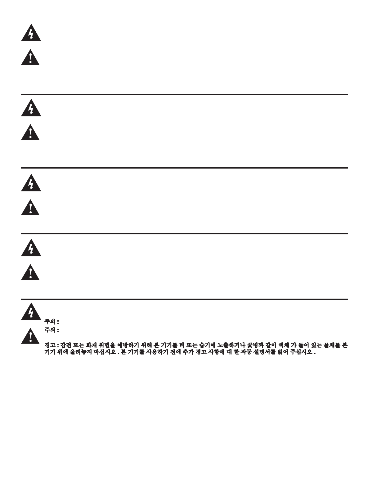
주의 : 감전 위험 — 열지 마십시오 !
주의 : 감전 위험을 낮추기 위해 덮개를 제거하지 마십시오 . 장치 내부에는 사용자가 직접 수리할 수 있는 부품이 없습니다 .
자격을 갖춘 서비스 요원에게 서비스를 의뢰하십시오 .
경고 : 감전 또는 화재 위험을 예방하기 위해 본 기기를 비 또는 습기에 노출하거나 꽃병과 같이 액체 가 들어 있는 물체를 본
기기 위에 올려놓지 마십시오 . 본 기기를 사용하기 전에 추가 경고 사항에 대 한 작동 설명서를 읽어 주십시오 .
Page 4

ENGLISH
IMPORTANT SAFETY INSTRUCTIONS
WARNING: When using electrical products, basic cautions should always be followed, including the following:
1. Read these instructions.
2. Keep these instructions.
3. Heed all warnings.
4. Follow all instructions.
5. Do not use this apparatus near water.
6. Clean only with a dry cloth.
7. Do not block any of the ventilation openings. Install in accordance with manufacturer’s instructions.
8. Do not install near any heat sources such as radiators, heat registers, stoves or other apparatus (including amplifiers) that
produce heat.
9. Do not defeat the safety purpose of the polarized or grounding-type plug. A polarized plug has two blades with one wider than
the other. A grounding type plug has two blades and a third grounding plug. The wide blade or third prong is provided for your
safety. If the provided plug does not fit into your outlet, consult an electrician for replacement of the obsolete outlet.
10. Protect the power cord from being walked on or pinched, particularly at plugs, convenience receptacles, and the point they exit
from the apparatus.
11. Only use attachments/accessories provided by the manufacturer.
12. Use only with a cart, stand, tripod, bracket, or table specified by the manufacturer, or sold with the apparatus. When a cart is
used, use caution when moving the cart/apparatus combination to avoid injury from tip-over.
13. Unplug this apparatus during lightning storms or when unused for long periods of time.
14. Refer all servicing to qualified service personnel. Servicing is required when the apparatus has been damaged in any way, such
as power-supply cord or plug is damaged, liquid has been spilled or objects have fallen into the apparatus, the apparatus has
been exposed to rain or moisture, does not operate normally, or has been dropped.
15. Never break off the ground pin. Write for our free booklet “Shock Hazard and Grounding.” Connect only to a power supply of the
type marked on the unit adjacent to the power supply cord.
16. If this product is to be mounted in an equipment rack, rear support should be provided.
17. Note for UK only: If the colors of the wires in the mains lead of this unit do not correspond with the terminals in your plug‚
proceed as follows: a) The wire that is colored green and yellow must be connected to the terminal that is marked by the letter
E‚ the earth symbol‚ colored green or colored green and yellow. b) The wire that is colored blue must be connected to the
terminal that is marked with the letter N or the color black. c) The wire that is colored brown must be connected to the terminal
that is marked with the letter L or the color red.
18. This electrical apparatus should not be exposed to dripping or splashing and care should be taken not to place objects
containing liquids, such as vases, upon the apparatus.
19. The on/off switch in this unit does not break both sides of the primary mains. Hazardous energy can be present inside the
chassis when the on/off switch is in the off position. The mains plug or appliance coupler is used as the disconnect device, the
disconnect device shall remain readily operable.
20. Exposure to extremely high noise levels may cause a permanent hearing loss. Individuals vary considerably in susceptibility to
noise-induced hearing loss, but nearly everyone will lose some hearing if exposed to sufficiently intense noise for a sufficient
time. The U.S. Government’s Occupational Safety and Health Administration (OSHA) has specified the following permissible
noise level exposures:
Duration Per Day In Hours Sound Level dBA, Slow Response
8 90
6 92
4 95
3 97
2 100
1 1⁄2 102
1 105
1⁄2 110
1⁄4 or less 115
According to OSHA, any exposure in excess of the above permissible limits could result in some hearing loss. Earplugs or protectors to
the ear canals or over the ears must be worn when operating this amplification system in order to prevent a permanent hearing loss, if
exposure is in excess of the limits as set forth above. To ensure against potentially dangerous exposure to high sound pressure levels, it is
recommended that all persons exposed to equipment capable of producing high sound pressure levels such as this amplification system be
protected by hearing protectors while this unit is in operation.
SAVE THESE INSTRUCTIONS!
Page 5

INSTRUCCIONES IMPORTANTES PARA SU SEGURIDAD
CUIDADO: Cuando use productos electrónicos, debe tomar precauciones básicas, incluyendo las siguientes:
1. Lea estas instrucciones.
2. Guarde estas instrucciones.
3. Haga caso de todos los consejos.
4. Siga todas las instrucciones.
5. No usar este aparato cerca del agua.
6. Limpiar solamente con una tela seca.
7. No bloquear ninguna de las salidas de ventilación. Instalar de acuerdo a las instrucciones del fabricante.
8. No instalar cerca de ninguna fuente de calor como radiadores, estufas, hornos u otros aparatos (incluyendo amplificadores) que
produzcan calor.
9. No retire la patilla protectora del enchufe polarizado o de tipo “a Tierra”. Un enchufe polarizado tiene dos puntas, una de ellas
más ancha que la otra. Un enchufe de tipo “a Tierra” tiene dos puntas y una tercera “a Tierra”. La punta ancha (la tercera ) se
proporciona para su seguridad. Si el enchufe proporcionado no encaja en su enchufe de red, consulte a un electricista para
que reemplaze su enchufe obsoleto.
10. Proteja el cable de alimentación para que no sea pisado o pinchado, particularmente en los enchufes, huecos, y los puntos que
salen del aparato.
11. Usar solamente añadidos/accesorios proporcionados por el fabricante.
12. Usar solamente un carro, pie, trípode, o soporte especificado por el fabricante, o vendido junto al aparato. Cuando se use
un carro, tenga cuidado al mover el conjunto carro/aparato para evitar que se dañe en un vuelco. No suspenda esta caja de
ninguna manera.
13. Desenchufe este aparato durante tormentas o cuando no sea usado durante largos periodos de tiempo.
14. Para cualquier reparación, acuda a personal de servicio cualificado. Se requieren reparaciones cuando el aparato ha
sido dañado de alguna manera, como cuando el cable de alimentación o el enchufe se han dañado, algún líquido ha sido
derramado o algún objeto ha caído dentro del aparato, el aparato ha sido expuesto a la lluvia o la humedad, no funciona de
manera normal, o ha sufrido una caída.
15. Nunca retire la patilla de Tierra.Escríbanos para obtener nuestro folleto gratuito “Shock Hazard and Grounding” (“Peligro de
Electrocución y Toma a Tierra”). Conecte el aparato sólo a una fuente de alimentación del tipo marcado al lado del cable de
alimentación.
16. Si este producto va a ser enracado con más equipo, use algún tipo de apoyo trasero.
17. Nota para el Reino Unido solamente: Si los colores de los cables en el enchufe principal de esta unidad no corresponden con
los terminales en su enchufe‚ proceda de la siguiente manera: a) El cable de color verde y amarillo debe ser conectado al
terminal que está marcado con la letra E‚ el símbolo de Tierra (earth)‚ coloreado en verde o en verde y amarillo. b) El cable
coloreado en azul debe ser conectado al terminal que está marcado con la letra N o el color negro. c) El cable coloreado en
marrón debe ser conectado al terminal que está marcado con la letra L o el color rojo.
18. Este aparato eléctrico no debe ser sometido a ningún tipo de goteo o salpicadura y se debe tener cuidado para no poner
objetos que contengan líquidos, como vasos, sobre el aparato.
19. El interruptor de en/lejos en esta unidad no rompe ambos lados de la red primaria. La energía peligrosa puede ser presente
dentro del chasis cuando el interruptor de en/lejos está en el de la posición. El tapón de la red o el acoplador del aparato son
utilizados como el desconecta dispositivo, el desconecta dispositivo se quedará fácilmente operable.
20. La exposición a altos niveles de ruido puede causar una pérdida permanente en la audición. La susceptibilidad a la pérdida de
audición provocada por el ruido varía según la persona, pero casi todo el mundo perderá algo de audición si se expone a un
nivel de ruido suficientemante intenso durante un tiempo determinado. El Departamento para la Salud y para la Seguridad del
Gobierno de los Estados Unidos (OSHA) ha especificado las siguientes exposiciones al ruido permisibles:
Duración por Día en Horas Nivel de Sonido dBA, Respuesta Lenta
8 90
6 92
4 95
3 97
2 100
1
1
⁄2 102
1 105
1
⁄2 110
1
⁄4 o menos 115
De acuerdo al OSHA, cualquier exposición que exceda los límites arriba indicados puede producir algún tipo de pérdida en la audición.
Protectores para los canales auditivos o tapones para los oídos deben ser usados cuando se opere con este sistema de sonido para prevenir una pérdida permanente en la audición, si la exposición excede los límites indicados más arriba. Para protegerse de una exposición
a altos niveles de sonido potencialmente peligrosa, se recomienda que todas las personas expuestas a equipamiento capaz de producir
altos niveles de presión sonora, tales como este sistema de amplificación, se encuentren protegidas por protectores auditivos mientras esta
unidad esté operando.
GUARDE ESTAS INSTRUCCIONES!
SPANISH
Page 6

FRENCH
INSTRUCTIONS IMPORTANTES DE SECURITE
ATTENTION: L’utilisation de tout appareil électrique doit être soumise aux precautions d’usage incluant:
1. Lire ces instructions.
2. Gardez ce manuel pour de futures références.
3. Prétez attention aux messages de précautions de ce manuel.
4. Suivez ces instructions.
5. N’utilisez pas cette unité proche de plans d’eau.
6. N’utilisez qu’un tissu sec pour le nettoyage de votre unité.
7. N’obstruez pas les systèmes de refroidissement de votre unité et installez votre unité en fonction des instructions de ce manuel.
8. Ne positionnez pas votre unité à proximité de toute source de chaleur.
9. Connectez toujours votre unité sur une alimentation munie de prise de terre utilisant le cordon d’alimentation fourni.
10. Protégez les connecteurs de votre unité et positionnez les cablages pour éviter toutes déconnexions accidentelles.
11. N’utilisez que des fixations approuvées par le fabriquant.
12. Lors de l’utilsation sur pied ou pole de support, assurez dans le cas de déplacement de l’ensemble enceinte/support de prévenir tout
basculement intempestif de celui-ci.
13. Il est conseillé de déconnecter du secteur votre unité en cas d’orage ou de durée prolongée sans utilisation.
14. Seul un technicien agréé par le fabriquant est à même de réparer/contrôler votre unité. Celle-ci doit être contrôlée si elle a subit des
dommages de manipulation, d’utilisation ou de stockage (humidité,…).
15. Ne déconnectez jamais la prise de terre de votre unité.
16. Si votre unité est destinée a etre montée en rack, des supports arriere doivent etre utilises.
17. Note pour les Royaumes-Unis: Si les couleurs de connecteurs du cable d’alimentation ne correspond pas au guide de la prise
secteur, procédez comme suit: a) Le connecteur vert et jaune doit être connectrer au terminal noté E, indiquant la prise de terre
ou correspondant aux couleurs verte ou verte et jaune du guide. b) Le connecteur Bleu doit être connectrer au terminal noté N,
correspondnat à la couleur noire du guide. c) Le connecteur marron doit être connectrer au terminal noté L, correspondant à la
couleur rouge du guide.
18. Cet équipement électrique ne doit en aucun cas être en contact avec un quelconque liquide et aucun objet contenant un liquide, vase
ou autre ne devrait être posé sur celui-ci. 1
9. L’interrupter (on-off) dans cette unité ne casse pas les deux côtés du primaire principal. L’énergie hasardeuse peut être preésente
dans châssis quand l’interrupter (on-off) est dans le de la position. Le bouchon principal ou atelage d’appareil est utilisé comme le
débrancher l’appareil restera facilement opérable.
20. Une exposition à de hauts niveaux sonores peut conduire à des dommages de l’écoute irréversibles. La susceptibilité au bruit varie
considérablement d’un individu à l’autre, mais une large majorité de la population expériencera une perte de l’écoute après une
exposition à une forte puissance sonore pour une durée prolongée. L’organisme de la santé américaine (OSHA) a produit le guide
ci-dessous en rapport à la perte occasionnée:
Durée par Jour (heures) Niveau sonore moyen (dBA)
8 90
6 92
4 95
3 97
2 100
1 1⁄2 102
1 105
1⁄2 110
1⁄4 ou inférieur 115
D’après les études menées par le OSHA, toute exposition au delà des limites décrites ce-dessus entrainera des pertes de l’écoute chez
la plupart des sujets. Le port de système de protection (casque, oreilette de filtrage,…) doit être observé lors de l’opération cette unité ou
des dommages irréversibles peuvent être occasionnés. Le port de ces systèmes doit être observé par toutes personnes susceptibles d’être
exposées à des conditions au delà des limites décrites ci-dessus.
GARDEZ CES INSTRUCTIONS!
Page 7

WICHTIGE SICHERHEITSHINWEISE
SICHERHEITSHINWEISEACHTUNG: Beim Einsatz von Elektrogeräten müssen u.a. grundlegende Vorsichtsmaßnahmen befolgt werden:
1. Lesen Sie sich diese Anweisungen durch.
2. Bewahren Sie diese Anweisungen auf.
3. Beachten Sie alle Warnungen.
4. Befolgen Sie alle Anweisungen.
5. Setzen Sie dieses Gerät nicht in der Nähe von Wasser ein.
6. Reinigen Sie es nur mit einem trockenen Tuch.
7. Blockieren Sie keine der Lüftungsöffnungen. Führen Sie die Installation gemäß den Anweisungen des Herstellers durch.
8. Installieren Sie das Gerät nicht neben Wärmequellen wie Heizungen, Heizgeräten, Öfen oder anderen Geräten (auch Verstärkern),
die Wärme erzeugen.
9. Beeinträchtigen Sie nicht die Sicherheitswirkung des gepolten Steckers bzw. des Erdungssteckers. Ein gepolter Stecker weist zwei
Stifte auf, von denen einer breiter ist als der andere. Ein Erdungsstecker weist zwei Stifte und einen dritten Erdungsstift auf. Der breite
Stift bzw. der dritte Stift dient Ihrer Sicherheit. Sollte der beiliegende Stecker nicht in Ihre Steckdose passen, wenden Sie sich bitte an
einen Elektriker, um die ungeeignete Steckdose austauschen zu lassen.
10. Schützen Sie das Netzkabel, sodass niemand darauf tritt oder es geknickt wird, insbesondere an Steckern oder Buchsen und ihren
Austrittsstellen aus dem Gerät.
11. Verwenden Sie nur die vom Hersteller erhältlichen Zubehörgeräte oder Zubehörteile.
12. Verwenden Sie nur einen Wagen, Stativ, Dreifuß, Träger oder Tisch, der den Angaben des Herstellers entspricht oder zusammen
mit dem Gerät verkauft wurde. Wird ein Wagen verwendet, bewegen Sie den Wagen mit dem darauf befindlichen Gerät besonders
vorsichtig, damit er nicht umkippt und möglicherweise jemand verletzt wird.
13. Trennen Sie das Gerät während eines Gewitters oder während längerer Zeiträume, in denen es nicht benutzt wird, von der
Stromversorgung.
14. Lassen Sie sämtliche Wartungsarbeiten von qualifizierten Kundendiensttechnikern durchführen. Eine Wartung ist erforderlich, wenn
das Gerät in irgendeiner Art beschädigt wurde, etwa wenn das Netzkabel oder der Netzstecker beschädigt wurden, Flüssigkeit oder
Gegenstände in das Gerät gelangt sind, das Gerät Regen oder Feuchtigkeit ausgesetzt wurde, nicht normal arbeitet oder heruntergefallen ist.
15. Der Erdungsstift darf nie entfernt werden. Auf Wunsch senden wir Ihnen gerne unsere kostenlose Broschüre „Shock Hazard and
Grounding“ (Gefahr durch elektrischen Schlag und Erdung) zu. Schließen Sie nur an die Stromversorgung der Art an, die am Gerät
neben dem Netzkabel angegeben ist.
16. Wenn dieses Produkt in ein Geräte-Rack eingebaut werden soll, muss eine Versorgung über die Rückseite eingerichtet werden.
17. Hinweis – Nur für Großbritannien: Sollte die Farbe der Drähte in der Netzleitung dieses Geräts nicht mit den Klemmen in Ihrem
Stecker übereinstimmen, gehen Sie folgendermaßen vor: a) Der grün-gelbe Draht muss an die mit E (Symbol für Erde) markierte
bzw. grüne oder grün-gelbe Klemme angeschlossen werden. b) Der blaue Draht muss an die mit N markierte bzw. schwarze Klemme
angeschlossen werden. c) Der braune Draht muss an die mit L markierte bzw. rote Klemme angeschlossen werden.
18. Dieses Gerät darf nicht ungeschützt Wassertropfen und Wasserspritzern ausgesetzt werden und es muss darauf geachtet werden,
dass keine mit Flüssigkeiten gefüllte Gegenstände, wie z. B. Blumenvasen, auf dem Gerät abgestellt werden.
19. Der Netzschalter in dieser Einheit bricht beide Seiten von den primären Haupleitungen nicht. Gerfährliche Energie kann anwesend
innerhalb des Chassis sein, wenn her Netzschalter im ab Poistion ist. Die Hauptleitungen stöpseln zu oder Gerätkupplung ist benutzt,
während das Vorrichtung abschaltet, das schaltet Vorrichtung wird bleiben sogleich hantierbar ab.
20. Belastung durch extrem hohe Lärmpegel kann zu dauerhaftem Gehörverlust führen. Die Anfälligkeit für durch Lärm bedingten
Gehörverlust ist von Mensch zu Mensch verschieden, das Gehör wird jedoch bei jedem in gewissem Maße geschädigt, der über
einen bestimmten Zeitraum ausreichend starkem Lärm ausgesetzt ist. Die US-Arbeitsschutzbehörde (Occupational and Health
Administration, OSHA) hat die folgenden zulässigen Pegel für Lärmbelastung festgelegt:
Dauer pro Tag in Stunden Geräuschpegel dBA, langsame Reaktion
8 90
6 92
4 95
3 97
2 100
1 1⁄2 102
1 105
1
⁄2 110
1
⁄4oderweniger 115
Laut OSHA kann jede Belastung über den obenstehenden zulässigen Grenzwerten zu einem gewissen Gehörverlust führen. Sollte die Belastung
die obenstehenden Grenzwerte übersteigen, müssen beim Betrieb dieses Verstärkungssystems Ohrenstopfen oder Schutzvorrichtungen im
Gehörgang oder über den Ohren getragen werden, um einen dauerhaften Gehörverlust zu verhindern. Um sich vor einer möglicherweise
gefährlichen Belastung durch hohe Schalldruckpegel zu schützen, wird allen Personen empfohlen, die mit Geräten arbeiten, die wie dieses
Verstärkungssystem hohe Schalldruckpegel erzeugen können, beim Betrieb dieses Geräts einen Gehörschutz zu tragen.
BEWAHREN SIE DIESE SICHERHEITSHINWEISE AUF!
DEUTSCH
Page 8

TÄRKEÄT TURVALLISUUSOHJEET
1. Lue nämä ohjeet.
2. Säilytä nämä ohjeet.
3. Huomioi kaikki varoitukset.
4. Noudata kaikkia ohjeita.
5. Älä käytä laitetta veden lähellä.
6. Puhdista vain kuivalla kankaalla.
7. Älä tuki mitään tuuletusaukkoja. Asenna valmistajan ohjeiden mukaisesti.
8. Älä asenna lämpölähteiden, kuten pattereiden, liesien tai muiden lämpöä tuottavien laitteiden (kuten vahvistinten) lähelle.
9. Älä poista polarisoidun tai maadoitustyyppisen tulpan suojausta. Polarisoidun tulpan toinen napa on leveämpi kuin toinen.
Maadoitustulpassa on kaksi napaa ja kolmas maadoitusnapa. Leveä napa ja maadoitusnapa on tarkoitettu turvaamaan laitteen
käyttöä. Jos mukana toimitettu tulppa ei sovi pistorasiaan, kutsu sähkömies vaihtamaan pistorasia, sillä se on vanhentunut.
10. Suojaa virtajohtoa päälle kävelemiseltä ja nipistykseltä, erityisesti pistotulppien, pistorasioiden sekä laitteen ulosvientien kohdalla.
11. Käytä vain valmistajan toimittamia lisälaitteita.
12. Käytä vain valmistajan määrittämän tai laitteen mukana myydyn vaunun, jalustan, kolmijalan, kiinnikkeen tai pöydän kanssa.
Käytettäessä vaunua liikuta vaunun ja laitteen yhdistelmää varovasti, jotta vältetään loukkaantumiset kaatumisesta johtuen.
13. Irrota laite sähköverkosta ukkosmyrskyjen aikana tai jos laitetta ei käytetä pitkään aikaan.
14. Huoltaminen tulee jättää pätevän huoltohenkilöstön tehtäväksi. Huoltoa tarvitaan, kun laite on jollakin tavoin vioittunut, esim.
virtalähteen johto tai pistoke on vioittunut, laitteen sisään on joutunut nestettä tai esineitä, laite on altistettu sateelle tai kosteudelle,
laite ei toimi normaalisti tai se on pudonnut.
15. Älä koskaan katkaise maadoitusnastaa. Ottamalla meihin yhteyttä saat kirjasen "Sähköiskuvaara ja maadoitus". Kytke vain
virtalähteeseen, joka vastaa laitteen virtajohdon viereen merkittyä tyyppiä.
16. Jos laite kiinnitetään laiteräkkiin, tulee se tukea takaosastaan.
17. Note for UK only: If the colors of the wires in the mains lead of this unit do not correspond with the terminals in your plug‚ proceed as
follows:
a) The wire that is colored green and yellow must be connected to the terminal that is marked by the letter E‚ the earth symbol‚
colored green or colored green and yellow.
b) The wire that is colored blue must be connected to the terminal that is marked with the letter N or the color black.
c) The wire that is colored brown must be connected to the terminal that is marked with the letter L or the color red.
18. Tätä sähkölaitetta ei tule altistaa nestetipoille tai roiskeille, eikä laitteen päälle saa asettaa nestettä sisältäviä esineitä, kuten
maljakoita.
19. Laitteen virtakytkin ei katkaise ensiövirran molempia puolia. Laitteen sisällä voi olla vaarallinen jännite, kun virtakytkin on poisasennossa. Virtajohto toimii pääkytkimenä, ja sen pitää olla aina käytettävissä.
20. Altistus erittäin korkeille äänitasoille voi aiheuttaa pysyvän kuulovaurion. Henkilöiden alttius melun aiheuttamille kuulovaurioille
vaihtelee, mutta lähes kaikkien kuulo vaurioituu altistuttaessa riittävän kovalle melulle riittävän kauan. Yhdysvaltain hallituksen
työturvallisuus- ja terveyshallinto (OSHA) on määrittänyt seuraavat hyväksyttävät melutasoaltistukset:
VAARA: Käytettäessä sähkölaitteita tulee aina huomioida mm. seuraavat turvallisuusohjeet:
OSHA:n mukaan altistus yo. tasoja korkeammalle määrälle voi aiheuttaa osittaisen kuulon menetyksen. Käytettäessä vahvistinjärjestelmää
tulee kuulovaurioiden estämiseksi käyttää korvatulppia tai kuulosuojaimia, mikäli altistus ylittää yllä asetetut rajat. Jotta vältetään mahdollisesti
vaarallinen altistus korkeille äänenpaineen tasoille, suositellaan, että kaikki korkeaa äänenpainetta tuottavien laitteiden, kuten tämän
vahvistimen, lähistöllä olevat henkilöt suojaavat kuulonsa, kun laite on käytössä.
Kesto päivää kohti tunteina Äänitaso dBA, hidas vaste
8 90
6 92
4 95
3 97
2 100
1 1⁄2 102
1 105
1⁄2 110
1⁄4 tai alle 115
SÄILYTÄ NÄMÄ OHJEET!
FINNISH
Page 9

VIKTIGA SÄKERHETSINSTRUKTIONER
1. Läs dessa instruktioner.
2. Behåll dessa instruktioner.
3. Iakttag alla varningar.
4. Följ alla instruktioner.
5. Använd inte apparaten i närheten av vatten.
6. Rengör endast med en torr trasa.
7. Blockera inte ventilationsöppningarna. Installera i enlighet med tillverkarens instruktioner.
8. Installera inte i närheten av värmekällor som radiatorer, varmluftsventiler, spisar eller andra apparater (inklusive förstärkare) som ger
ifrån sig värme.
9. Motverka inte säkerhetsfunktionen hos en jordad stickkontakt. En jordad stickkontakt har två stift och metallbleck på sidorna.
Metallblecket finns där för din säkerhet. Kontakta en elektriker för utbyte av det föråldrade vägguttaget om den medföljande
stickkontakten inte passar i ditt vägguttag.
10. Skydda strömsladden från att klivas på eller klämmas, särskilt vid kontakten, grenuttag och platsen där den lämnar apparaten.
11. Använd enbart tillsatser/tillbehör som tillhandahålls av tillverkaren.
12. Använd endast med en kärra, ställ, trefot, fäste eller bord i enlighet med tillverkarens specikationer, eller som säljs tillsammans med
apparaten. Var försiktig när du använder en kärra så att inga personskador uppstår på grund av att kombinationen kärra-apparat
välter när den yttas.
13. Koppla ur apparaten vid åskväder eller när den inte används under en längre tid.
14. Låt kvalicerad servicepersonal sköta all service. Service krävs om apparaten har skadats på något vis, till exempel om strömsladden
eller stickkontakten har skadats, vätska har spillts eller föremål har fallit ner i apparaten, apparaten har utsatts för regn eller fukt, inte
fungerar normalt eller har tappats.
15. Anslut aldrig till ojordade uttag. Skriv till oss för vårt gratishäfte ”Stötrisk och jordning”. Anslut endast till en strömkälla av samma typ
som enhetens märkning anger (bredvid strömsladden).
16. Om produkten ska monteras i ett utrustningsrack bör bakre stöd användas.
17. Note for UK only: If the colors of the wires in the mains lead of this unit do not correspond with the terminals in your plug‚ proceed as
follows:
a) The wire that is colored green and yellow must be connected to the terminal that is marked by the letter E‚ the earth symbol‚
colored green or colored green and yellow.
b) The wire that is colored blue must be connected to the terminal that is marked with the letter N or the color black.
c) The wire that is colored brown must be connected to the terminal that is marked with the letter L or the color red.
18. Denna elektriska apparat bör inte utsättas för dropp eller stänk och försiktighet bör iakttas så att inte föremål som innehåller vätskor,
såsom vaser, placeras ovanpå apparaten.
19. Enhetens strömbrytare bryter inte båda sidor av strömkretsen. Farlig energi kan förekoma inuti höljet när strömbrytaren är i av-läget.
Stickkontakten eller apparatkontakten fungerar som bortkopplingsenhet, bortkopplingsenheten ska hållas lättillgänglig.
20. Extremt höga ljudnivåer kan orsaka permanent hörselskada. Olika personer skiljer sig åt i benägenhet att få hörselskador av
oljud, men i princip alla får hörselskador om de utsätts för tillräckligt höga ljud under tillräcklig tid. Den amerikanska regeringens
arbetsskydds- och hälsoförvaltning (OSHA) har angivit följande maxnivåer för tillåten exponering för oljud:
VARNING: När du använder elektriska produkter ska grundläggande försiktighetsåtgärder iakttas, inklusive följande:
Enligt OSHA kan exponering utöver ovanstående tillåtna gränser orsaka hörselskador. Öronproppar eller skydd för hörselgången eller
över öronen måste bäras när detta förstärkarsystem används för att förebygga permanenta hörselskador, om exponeringen överskrider
gränsvärdena enligt ovan. För att skydda mot potentiellt farlig exponering för höga ljudtrycksnivåer rekommenderas det att personer
som exponeras för utrustning som kan producera höga ljudtrycksnivåer såsom detta förstärkarsystem skyddas med hörselskydd när
enheten är i drift.
Längd per dag i timmar Ljudnivå dBA, långsam svarstid
8 90
6 92
4 95
3 97
2 100
1 1⁄2 102
1 105
1⁄2 110
1⁄4 eller mindre 115
SPARA DESSA INSTRUKTIONER!
SWEDISH
Page 10

ITALIAN
IMPORTANTI NORME DI SICUREZZA:
ATTENZIONE: Durante uso di apparecchiature elettriche vanno osservate alcune precauzioni basilari, tra cui le seguenti:
1. Leggete queste istruzioni.
2. Conservate le istruzioni.
3. Rispettate tutte le avvertenze.
4. Seguite le istruzioni.
5. Non usate questo prodotto vicino all’acqua.
6. Pulite esclusivamente con un panno asciutto.
7. Non ostruite le fessure di ventilazione. Installate il dispositivo seguendo le istruzioni del produttore.
8. Il prodotto va collocato lontano da sorgenti di calore quali radiatori, pompe di calore, stufe o altri dispositivi che generano calore
(compresi gli amplificatori).
9. Non eliminate i dispositivi di sicurezza come spine polarizzate o con messa a terra. La spina polarizzata ha due lame, una
più grande dell’altra. La spina con messa a terra ha due contatti più un terzo per la terra. Il contatto più largo o terzo polo è
indispensabile per la vostra sicurezza. Se la spina fornita non adatta alla vostra presa, mettetevi in contatto con un elettricista
per la sostituzione della presa obsoleta.
10. Fate attenzione a non camminare o incastrare il cavo di alimentazione, soprattutto in prossimità della spina o del punto in cui si
collega all’apparecchiatura.
11. Usate solo accessori originali forniti dal costruttore.
12. L’apparato va usato esclusivamente con il supporto indicato dal produttore o venduto con l’apparato. Se intendete adoperare un
carrello su ruote, fate attenzione quando spostate apparecchio e supporto per evitare che la loro caduta possa causare danni a
cose o persone.
13. Scollegatelo l’apparecchio dalla presa di corrente durante un temporale con fulmini o quando non s’intende usare per un lungo
periodo.
14. L’assistenza va eseguita esclusivamente da personale autorizzato. È necessario ricorrere all’assistenza se il dispositivo ha
subito danni, per esempio si sono rovinati il cavo di alimentazione o la spina, all’interno è caduto del liquido o un oggetto, il
dispositivo è rimasto esposto alla pioggia o all’umidità, non funziona normalmente o è caduto a terra.
15 Non rimuovete lo spinotto della terra. Collegate il dispositivo esclusivamente a una presa di corrente del tipo indicato accanto
alla targhetta posta vicino al cavo di alimentazione.
16. Se questo prodotto deve essere montato a rack, è necessario sostenerlo anche nella parte posteriore.
17. Nota per UK: Se i colori dei fili nel cavo di alimentazione per questa unità non corrispondono con i terminali della vostra spina,
procedere come segue: a) Il filo di colore verde/giallo deve essere collegato al terminale che marcato con lettera E, o simbolo di
terra, o colore verde o verde/giallo. b) Il filo di colore blu deve essere collegato al terminale marcato con la lettera N o di colore
Nero. c) Il filo di colore marrone deve essere collegato al terminale marcato con la lettera L o di colore Rosso.
18. Questo apparato elettrico non deve essere esposto a gocce o schizzi, va in ogni caso evitato di appoggiare oggetti contenenti
liquidi, come bicchieri, sull'apparecchio.
19. L'interruttore on/off in questa unità non interrompe entrambi i lati della rete di alimentazione. All'interno dell'apparecchio può
essere presente elettricità anche con interruttore on/off in posizione off. La spina o il cavo di alimentazione è utilizzato come
sezionatore, il dispositivo di sezionamento deve restare sempre operativo.
20. L’esposizione a livelli di volume molto elevati può causare la perdita permanente dell’udito. La predisposizione alla perdita
dell’udito causata da livelli elevati di volume varia notevolmente da persona a persona, ma quasi tutti subiscono una perdita di
udito almeno parziale se soggetti a volume di livello elevato per un tempo sufficientemente lungo. L’ufficio Lavoro e Salute del
governo degli USA (OSHA) ha elaborato la seguente tabella di tolleranza ai rumori:
Esposizione giornaliera in ore Livello sonoro dBA, Slow response
8 90
6 92
4 95
3 97
2 100
1 1⁄2 102
1 110
1⁄4 o minore 115
Secondo l’OSHA, l’esposizione a livelli di volume al di sopra dei limiti stabiliti può causare una perdita almeno parziale dell’udito. Quando
si adopera questo sistema di amplificazione, è necessario indossare auricolari o apposite protezioni per il condotto auditivo, per evitare la
perdita permanente dell’udito se l’esposizione supera i limiti sopra riportati.Per evitare di esporvi al rischio di danni derivanti da elevati livelli
di pressione sonora, si raccomanda di adoperare delle protezioni per gli orecchi quando si usano attrezzature in grado di produrre elevati
livelli sonori, come quest’amplificatore.
CONSERVATE QUESTE ISTRUZIONI!
Page 11

Portuguese
INSTRUÇÕES IMPORTANTES DE SEGURANÇA
1. Leia estas instruções.
2. Mantenha estas instruções.
3. Preste atenção a todas as advertências.
4. Siga todas as instruções.
5. Não use este aparelho perto d’água.
6. Limpe somente com um pano seco.
7. Não obstrua nenhuma das aberturas de ventilação. Instale de acordo com as instruções do fabricante.
8. Não instale perto de nenhuma fonte de calor tais como radiadores, registros de calor, fogões ou outros aparelhos (incluindo
amplicadores) que produzam calor.
9. Não desae o propósito de segurança do plugue polarizado ou do tipo aterrado. Um plugue polarizado tem duas lâminas com uma
mais larga que a outra. Um plugue do tipo aterrado tem duas lâminas e um terceiro plugue terra. A lâmina larga ou o terceiro pino
são fornecidos para sua segurança. Se o plugue disponibilizado não couber em sua tomada, consulte um eletricista para troca da
tomada obsoleta.
10. Proteja o cabo de energia para não ser pisado ou espremido principalmente em plugues, recipientes e o ponto de onde sai do
aparelho.
11. Use apenas conexões/acessórios fornecidos pelo fabricante.
12. Use apenas um carrinho, banqueta, tripé, suporte, ou mesa especicado pelo fabricante, ou vendido com o aparelho. Quando um
carrinho for usado, tome cuidado ao mover a combinação carrinho/aparelho para evitar ferimentos por tombamento.
13. Tire esse aparelho da tomada durante tempestades de raios ou quando for car sem usar por longos períodos de tempo.
14. Entregue todos os consertos apenas a pessoal qualificado. O conserto é necessário quando o aparelho tiver sofrido qualquer
dano, tais como o cabo de energia ou plugue estiverem danicados, líquidos tenham sido derramados ou objetos tenham caído no
aparelho, o aparelho tenha sido submetido à chuva ou umidade, não funcionar normalmente, ou tenha sido deixado cair.
15. Nunca quebre fora o pino terra. Escreva pedindo nosso livreto grátis “Perigos de Choque e Aterramento.” Ligue apenas a um
suprimento de energia do tipo marcado na unidade adjacente ao o de fornecimento de energia.
16. Se este produto for ser montado em uma estante para equipamentos, deve ser montado um suporte traseiro.
17. Note for UK only: If the colors of the wires in the mains lead of this unit do not correspond with the terminals in your plug‚ proceed as
follows:
a) The wire that is colored green and yellow must be connected to the terminal that is marked by the letter E‚ the earth symbol‚
colored green or colored green and yellow.
b) The wire that is colored blue must be connected to the terminal that is marked with the letter N or the color black.
c) The wire that is colored brown must be connected to the terminal that is marked with the letter L or the color red.
18. Este aparelho elétrico não deve ser exposto a pingos ou respingos e deve ser tomado cuidado para não colocar objetos contendo
líquidos, tais como vasos, sobre o aparelho.
19. O comutador liga/desliga nesta unidade não interrompe ambos os lados da rede elétrica primária. Energia perigosa pode estar
presente dentro do chassi quando o comutador liga/desliga estiver na posição desligado. O plugue de alimentação ou um dispositivo
de união é usado como dispositivo de desligamento, o dispositivo de desligamento deve permanecer pronto para funcionar.
20. Exposição a níveis de barulho extremamente altos podem causar perda permanente de audição. As pessoas variam
consideravelmente em susceptibilidade a perda de audição causada por ruídos, mas quase todo mundo vai perder algo da audição
se exposto a ruído sucientemente intenso por tempo suciente. A Administração de Segurança Ocupacional e Saúde americana
(OSHA) especicou os seguintes níveis permissíveis de exposição a ruído:
ADVERTÊNCIA: Ao usar eletrodomésticos, precauções básicas devem sempre ser seguidas, incluindo as seguintes:
De acordo com a OSHA, qualquer exposição excedente aos limites permissíveis acima pode resultar em alguma perda de audição. Tampões de
ouvido ou protetores sobre os canais do ouvido ou sobre as orelhas precisam ser usados ao operar este sistema de amplicação para poder evitar
uma perda permanente de audição, se a exposição for em excesso aos limites acima estabelecidos. Para assegurar contra exposição perigosa
potencial a níveis de alta pressão de ruído, é recomendado que todas as pessoas expostas a equipamento capaz de produzir níveis de alta pressão
de ruído tais como este sistema de amplicação estejam protegidas por protetores de ouvido enquanto esta unidade estiver em funcionamento.
Duração Por Dia Em Horas dBA de Nível de Som, Resposta Lenta
8 90
6 92
4 95
3 97
2 100
1 1⁄2 102
1 105
1⁄2 110
1⁄4 ou menos 115
GUARDE ESSAS INSTRUÇÕES!
Page 12

安全のための重要事項
警告: 電気製品を使用するときは、次の項目を含め、基本的な注意事項を常にお守りください。
1. 本書の指示内容をお読みください。
2. 本書は保管してください。
3. すべての警告に注意してください。
4. すべての指示に従ってください。
5. 本装置を水の近くで使用しないでください。
6. お手入れには乾いた布をお使いください。
7. 開口部をふさがないでください。メーカーの指示に従って設置してください。
8. ラジエータ、ストーブなど (アンプを含む)、発熱体の近くに設置しないでください。
9. 分極プラグや接地プラグの安全性を損なわないようにしてください。分極プラグの2つのブレードは、一方が他より幅広くなっています。
接地式のプラグには2つのブレードと接地プラグがあります。幅広のブレードや接地プラグは安全のために付けられています。所定のプ
ラグがコンセントなどに合わない場合、旧式のコンセントなどの交換について技術者に問い合わせてください。
10. 電源コードを踏んだり挟んだりしないように保護してください。特にプラグ、コンセント、装置から出る部分を保護してください。
11. 備品/付属品はメーカーのものを使用してください。
12. カート、スタンド、三脚、ブラケット、テーブルなどは、メーカー指定のもの、または装置とともに販売されているもの使用してください。カ
ートを使用するときは、カートと装置を動かしたときに横転などでケガをしないよう注意してください。
13. 落雷の恐れのある嵐のとき、または長期間使用しないときは本装置の電源を外してください。
14. 保守作業はすべて資格のあるサービス担当者に依頼してください。保守作業が必要になるのは、装置が故障した場合、たとえば、電源
コードやプラグが破損、装置に液体がかかる。物が落ちる、雨など湿度の影響を受ける、正常に動作しない、落下した場合などです。
15. グランドピン(接地ピン)は決して取り外さないでください。フリーブックレット「感電と接地」を入手してください。装置の電源コードの横
に記載されているタイプの電源にのみ接続してください。
16. 本製品をラックに載せる場合は、背面を支持するものが必要です。
17. Note for UK only: If the colors of the wires in the mains lead of this unit do not correspond with the terminals in your plug‚ proceed as
follows: a) The wire that is colored green and yellow must be connected to the terminal that is marked by the letter E‚ the earth symbol‚
colored green or colored green and yellow. b) The wire that is colored blue must be connected to the terminal that is marked with the letter
N or the color black. c) The wire that is colored brown must be connected to the terminal that is marked with the letter L or the color red.
18. 電気機器に水がかからないようにしてください。花瓶など液体の入ったものを装置に置かないように注意してください。
19. オン/オフスイッチは、主電源のどちらの側も切断しません。オン/オフスイッチがオフ位置のとき、シャシー内部のエネルギー(高電圧)
は危険なレベルにあります。主電源プラグまたは機器のカプラが切断装置になっています。切断装置はすぐに動作し使用できる状態に
しておく必要があります。
20. 極めて高い騒音レベルは聴覚を永久に損なう原因になることがあります。騒音による聴覚障害の可能性は人によって異なりますが、十
分に高い騒音を十分長い時間浴びた場合には、ほぼすべての人が何らかの障害を被ります。米国労働安全衛生庁 (OSHA) は、許容
できるノイズレベル(騒音暴露レベル)を次のように定めています。
1日当たりの時間 サウンドレベルdBA、スローレスポンス
8 90
6 92
4 95
3 97
2 100
1½ 102
1 105
½ 110
1⁄4以下 115
OSHAによると、上記許容限度を超える場合は聴覚障害の原因になります。騒音が上記限度を超える場合は、永久的な聴覚障害を避けるため、このアンプシステ
ムの操作時に、外耳道または耳全体にイヤプラグやプロテクタを装着する必要があります。高音圧レベルによる危険な状態を避けるため、このアンプシステムのよ
うな高音圧レベルを出力する機器に触れる人はすべて、本機を使用中はプロテクタにより聴覚を保護することをおすすめします。
本書は保管してください!
JAPANESE
Page 13

重要安全事项
1. 阅读说明书。
2. 妥善保管说明书。
3. 注意所有安全警告。
4. 按照要求和指示操作。
5. 请勿在靠近水(或其它液体)的地方使用本机。
6. 本机只能用干燥布料擦拭。
7. 请勿遮盖任何通散热口。确实依照本说明书安装本机。
8. 请勿将本机安装在任何热源附近,例如电暖器、蓄热器件、火炉或其他发热电器(包括功率放大器)。
9. 请勿破坏两脚型插头或接地型插头的安全装置。两脚型插头有两个不同宽度的插头片,一个窄,另一个宽一点。接地型插头有两个相同
的插头片和一个接地插脚。两脚型插头中宽的插头片和接地型插头接地插脚起着保障安全的作用。如果所附带的插头规格与您的插座不
匹配,请让电工更换插座以保证安全。
10. 请勿踩踏或挤压电源线,尤其是插头、插座、设备电源输入接口或者电源线和机身连接处。
11. 本机只可以使用制造商指定的零件 / 配件。
12. 本机只可以使用与本机搭售或由制造商指定的机柜、支架、三角架、托架或桌子。使用机柜时,请小心移动已安装设备的机柜,以避免
机会推翻造成身体伤害。
13. 在雷雨天或长期不使用的情况下,请拔掉电源插头。
14. 所有检查与维修都必须由指定的专业维修人员进行。如本机的任何形式的损伤都须检修,例如电源线或插头受损,有液体或物体落入机
身内,曾暴露于雨天或潮湿的地方,不能正常运作,或曾掉落后损坏等。
15. 不得拔出接地插脚。请写信索取免费手册《 Shock Hazard and Grounding》。使用前,请仔细检查确认所使用的电源电压是否匹配设备
上标注的额定电压。
16. 如果本机装在机柜中 , 其后部也应给予相应的支撑固定。
17.
Note for UK only: If the colors of the wires in the mains lead of this unit do not correspond with the terminals in your plug‚ proceed as
follows:
a) The wire that is colored green and yellow must be connected to the terminal that is marked by the letter E‚ the earth symbol‚
colored green or colored green and yellow.
b) The wire that is colored blue must be connected to the terminal that is marked with the letter N or the color black.
c) The wire that is colored brown must be connected to the terminal that is marked with the letter L or the color red.
18. 本机不得暴露于滴水或溅水中。请勿将诸如花瓶等装有液体的物体放置于本机上。
19. 本机电源开关不能同时断开两端的电源,完全切断外部电源。因此当开关位于“OFF”位置时,本机外壳仍有可能带有触电的危险。电
源插头或耦合器能够与设备或者电源容易分开,保证电源的完全切断,从而保证安全。
20. 声压级较高的噪音容易造成听力的永久性损失。因噪声而造成的听力损失程度 , 个体间的差异较大 , 但几乎每个人在声压级较高的噪音
环境里一定时间,都会有不同程度的听力损失。美国政府职业安全与保健管理局(OSHA)就此规定了下列容许噪声级 :
警告 :操作电器产品时,请务必遵守基本安全注意事项,包括 :
据 OSHA, 任何超出以上所允许的范围 , 都会造成部分听力的损失。使用本功放系统时,必须佩戴如耳塞等保护耳朵的器件,防止长时间处于上述
限制级以上的环境而引起永久性听力受损。本机运行时,如果超过上述所规定的最大限制,为了抵御较高的声压对于听受损所造成的潜在危险,建
议使用诸如功放系统等引起高声压级噪声的所有人均佩戴保护耳朵的器件。
每天持续小时数 声压级(dBA)慢反应
8 90
6 92
4 95
3 97
2 100
1
½
102
1 105
½
110
¼
或更少 115
请妥善保管本说明书!
CHINESE
Page 14

중요 안전 지침
경고: 전기 제품 사용 시 다음 사항을 포함해 기본적인 주의 사항을 항상 따라야 합니다.
1. 이 지침을 읽어 주십시오.
2. 이 지침을 준수하여 주십시오.
3. 모든 경고 사항에 주의해 주십시오.
4. 모든 지침을 따라 주십시오.
5. 물기가 있는 근처에서 이 기기를 사용하지 마십시오.
6. 마른 헝겊으로만 청소해 주십시오.
7. 통풍구를 막지 마십시오. 제조업체의 지침에 따라 설치해 주십시오.
8. 라디에이터, 가열기, 난로 또는 열을 발산하는 기타 기기(앰프 포함) 근처에 설치하지 마십시오.
9. 극성 플러그나 접지형 플러그의 안전 용도를 무시하지 마십시오. 극성 플러그는 한쪽 날이 다른 쪽보다 더 넓습니다. 접지형
플러그에는 2개의 날과 1개의 접지 플러그가 있습니다. 넓은 날 또는 1개의 접지 플러그는 안전을
위해 제공됩니다. 제공된
플러그가 사용자의 콘센트에 맞지 않으면 구식 콘센트의 교체에 대해 전기 기술자에게 문의하십시오.
10. 전원 코드 특히, 플러그, 소켓 및 기기에서 나오는 지점이 밟히거나 집히지 않도록 보호하십시오.
11. 제조업체에서 제공하는 부착 장치/액세서리만을 사용하십시오.
12. 제조업체에서 지정하거나 기기와 함께 판매되는 카트, 스탠드, 삼각대, 브래킷 또는 테이블만을 사용하십시오. 카트 사용 시
카트/기기 결합물을 움직일 때 전복으로 인해 부상을 입지 않도록 주의해 주십시오.
13. 번개와 폭풍이 올 때 그리고 장기간 사용하지 않을 때는 이 기기의 플러그를 뽑아 놓으십시오.
14. 자격을 갖춘 서비스 요원에게 모든 서비스를 의뢰하십시오. 전원 공급 코드 또는 플러그가 손상되거나 액체
를 엎지르거나 기
기 안에 이물질을 떨어뜨리거나 비 또는 습기에 기기를 노출하거나 정상적으로 작동하지 않거나 기기를 떨어뜨린 경우와 같
이 기기가 손상된 경우에는 서비스를 받아야 합니다.
15. 접지 핀을 제거하지 마십시오. 당사의 무료 소책자인 “감전 위험 및 접지”을 우편으로 주문해 주십시오. 전원 공급 코드의 기
기에 표시된 유형의 전원 공급 장치만 연결해 주십시오.
16. 이 제품을 장비 랙에 장착할 경우에는 후면 지지대를 설비해야 합니다.
17. Note for UK only: If the colors of the wires in the mains lead of this unit do not correspond with the terminals in your plug‚ proceed as
follows: a) The wire that is colored green and yellow must be connected to the terminal that is marked by the letter E‚ the earth symbol‚
colored green or colored green and yellow. b) The wire that is colored blue must be connected to the terminal that is marked with the letter
N or the color black. c) The wire that is colored brown must be connected to the terminal that is marked with the letter L or the color red.
18.
전기 기기가 비나 물방울에 노출되지 않도록 주의하고 꽃병과 같이 용액이 들어 있는 물체를 기기 위에 놓지 않도록 주의해
주십시오.
19. 본 기기의 ON/OFF 스위치는 양쪽의 주 기기 전원을 차단하지 않습니다. ON/OFF 스위치가
OFF 위치에 있더라도 섀시 내부
에 위험한 전기가 흐를 수 있습니다. 기본 플러그 또는 기기 커플러는 분리 장치로 사용됩니다. 분리 장치는 바로 사용 가능
한 상태로 두어야 합니다.
20. 매우 높은 소음에 노출되면 영구적으로 청각이 손상될 수 있습니다. 소음으로 인한 청각 손상 가능성은 개인별로 매우 다르
지만 장시간 매우 강한 소음에 노출되면 거의 모든 사람들에게 어느 정도의 청각 손상이 발생합니다. 미국 정부의 OSHA(작
업 안전 및 건강 관리국)은 다음과 같이 용인 가능한 소음 노출을 규정하고 있습니다.
일별 지속 시간 소음 수준 dBA, 저속 반응
8 90
6 92
4 95
3 97
2 100
1½ 102
1 105
½ 110
¼ 이하 115
OSHA에 따르면 용인 가능한 위 제한 수치를 초과하여 노출된 경우 일부 청각이 손상될 수 있습니다. 위에 명시된 제한치를 초과하여
노출되는 경우 영구적인 청각 손상을 예방하려면 이 앰프 시스템 사용 시 귀마개 또는 귀 전체를 덮는 보호구를 착용해야 합니다. 잠
재적으로 위험한 높은 음압에 노출되지 않도록 하려면 이 앰프 시스템과 같이 높은 음압을 생성할 수 있는 장비에 노출되는 모든 사람
이 기기가 작동하는 동안 청각 보호구를 착용하는 것이 좋습니다.
이 지침을 잘 보관해 주십시오!
KOREAN
Page 15

ENGLISH
3120
The Peavey 3120 guitar amplier simply shreds. From its high-gain input to paralleled speaker output jacks, the Peavey 3120 is
not for the faint of heart. This amplier is loaded with practical features useful in real-world applications that deliver an earthquaking 120 watts of pure tube power. The Rhythm and Lead channels have gain controls to assist in taming this beast while
achieving killer sound. Tone contour is accomplished through passive controls for Bass, Mid, and Treble on the Clean channel,
while the Rhythm and Lead channels utilize Peavey’s exclusive Bass, Middle, and Treble active controls. Designed to work
equally well into 4, 8, or 16-ohm loads, matching this monster to a cabinet is limited only by your imagination.
FEATURES
• Three 12AX7 preamp tubes
• Four EL34 power amp tubes driven by a 12AX7
• Power amp convertible to use four 6L6GC tubes
• Footswitchable effects loop with independent send and return controls
• Damping switch (tight, medium, loose)
• Special noise gate circuitry on Rhythm and Lead channels
• Line out with level control
• Cabinet impedance switch (4, 8, or 16 Ohms)
• Heavy-duty power, standby and channel select toggle switches
• Classic power status indicator lamp
15
Page 16
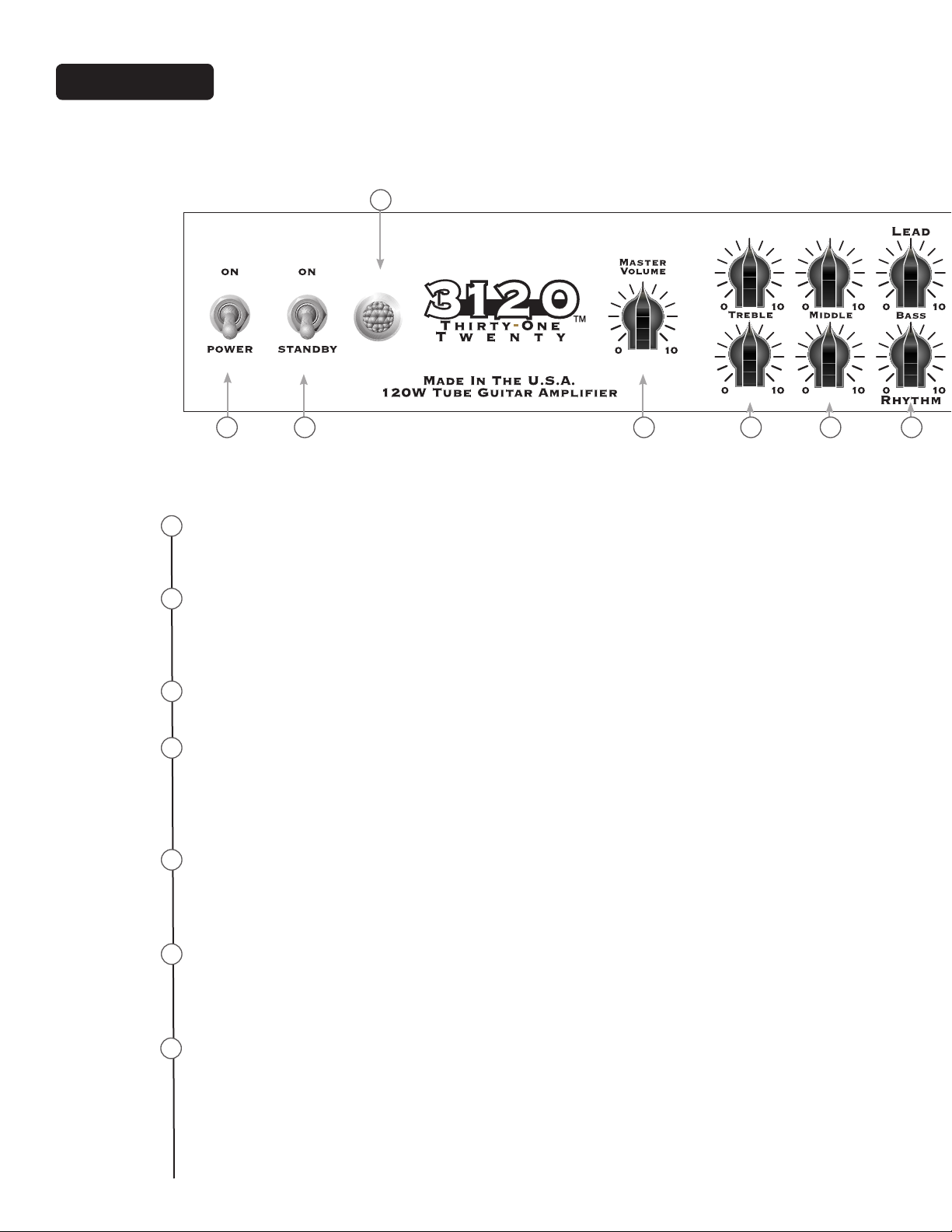
Front Panel
3
1 2 4 5 6 7
1
POWER SWITCH
This two-way toggle switch applies mains power to the unit. The amber power status lamp (3) will illuminate when this switch is in the ON position.
2
STANDBY SWITCH
This two-way toggle switch allows the amp to be placed in the STANDBY mode.
In the STANDBY position the tubes stay hot but the amplier is not operational.
Switching to the ON position places the amp in active mode.
3
POWER STATUS LAMP
This indicator illuminates when mains power is being supplied to the amp.
4
MASTER VOLUME
This control sets the overall volume level of the amp. Once the desired balance
between the three channels in the amplier has been achieved, the entire output
level of the unit can be increased or decreased by rotating this control. Clockwise
rotation increases level; counterclockwise rotation decreases level.
5
TREBLE
This control, on both the Rhythm and Lead channels, varies the high frequency
response of the amplier. It is an active control (shelving type) and allows 15 dB of
boost or cut.
6
MIDDLE
This control, on both the Rhythm and Lead channels, varies the mid frequency
response of the amplier. It is an active control (peak/notch type) and allows 15 dB
of boost or cut.
7
BASS
This control, on both the Rhythm and Lead channels, varies the low frequency
response of the amplier. It is an active control (shelving type) and allows 15 dB of
boost or cut.
16
Page 17
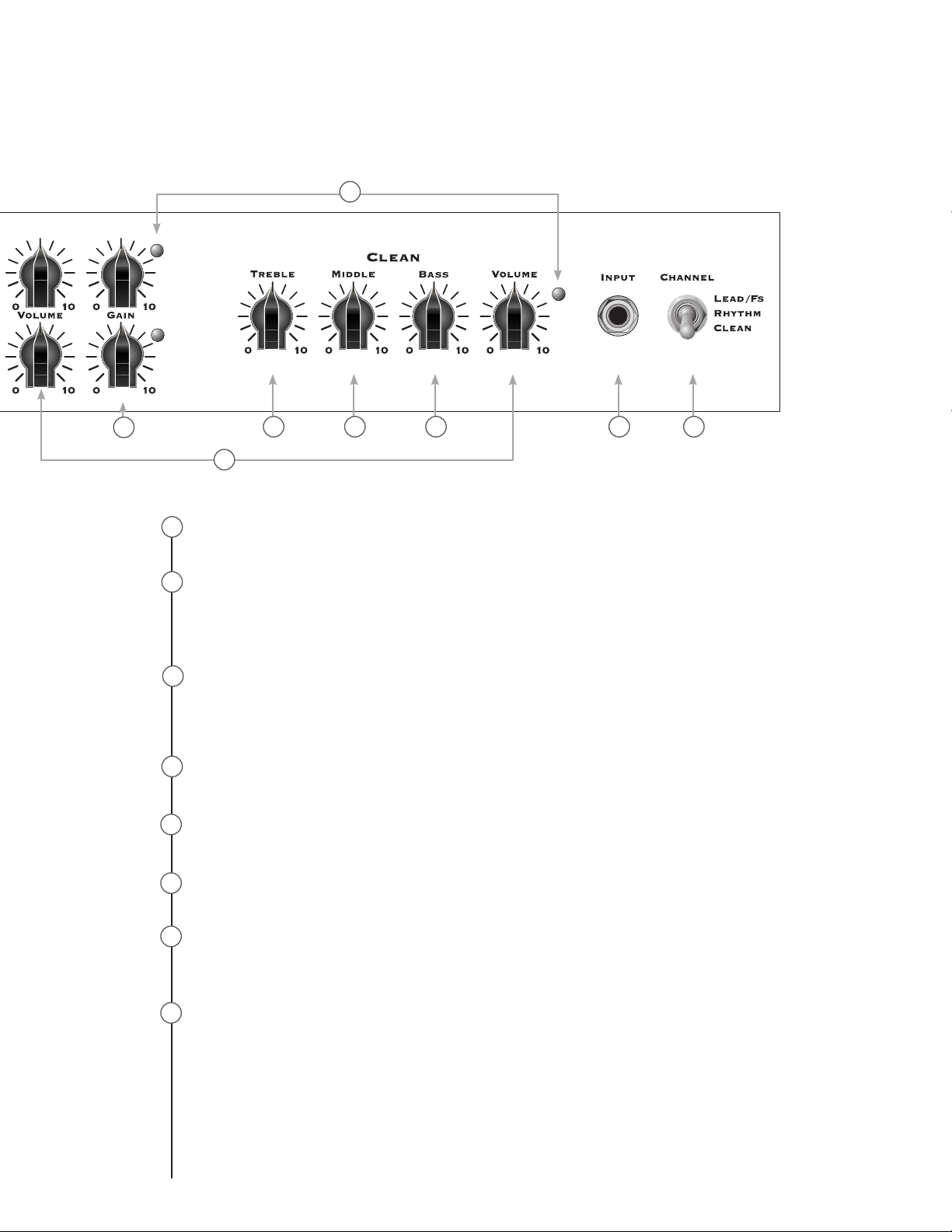
10
9
8
8
VOLUME
11 12 13 14 15
This control, on all three channels, sets the overall level of its respective channel.
9
GAIN
This control, on both the Rhythm and Lead channels, controls the input volume
level of the channel. Rotating this control clockwise will increase the amount of
preamp distortion and sustain.
10
CHANNEL ACTIVATION LEDs
These indicators signify which channel is active. Lead channel activation illuminates
the red LED; Rhythm channel activation illuminates the yellow LED; and Clean channel activation illuminates the green LED.
11
TREBLE
This passive control regulates the high frequencies for the Clean channel.
12
MID
This passive control regulates the mid frequencies for the Clean channel.
BASS
13
This passive control regulates the low frequencies for the Clean channel.
14
INPUT
This 1/4” jack is designed to accommodate most any guitar output signal. Input signal gain can be adjusted by the GAIN (9) controls (Rhythm and Lead channels only).
CHANNEL SELECT SWITCH
15
This three-position toggle switch allows selection between the amplier’s three
channels. LED (10) illumination indicates which channel is active. Channel switching can also be accomplished by footswitch. See the FOOTSWITCH section of this
manual for explanation of switch operation. The CHANNEL SELECT SWITCH must be
set in the Lead position in order for the footswitch to operate properly.
17
Page 18
Rear Panel
1 3 4 652
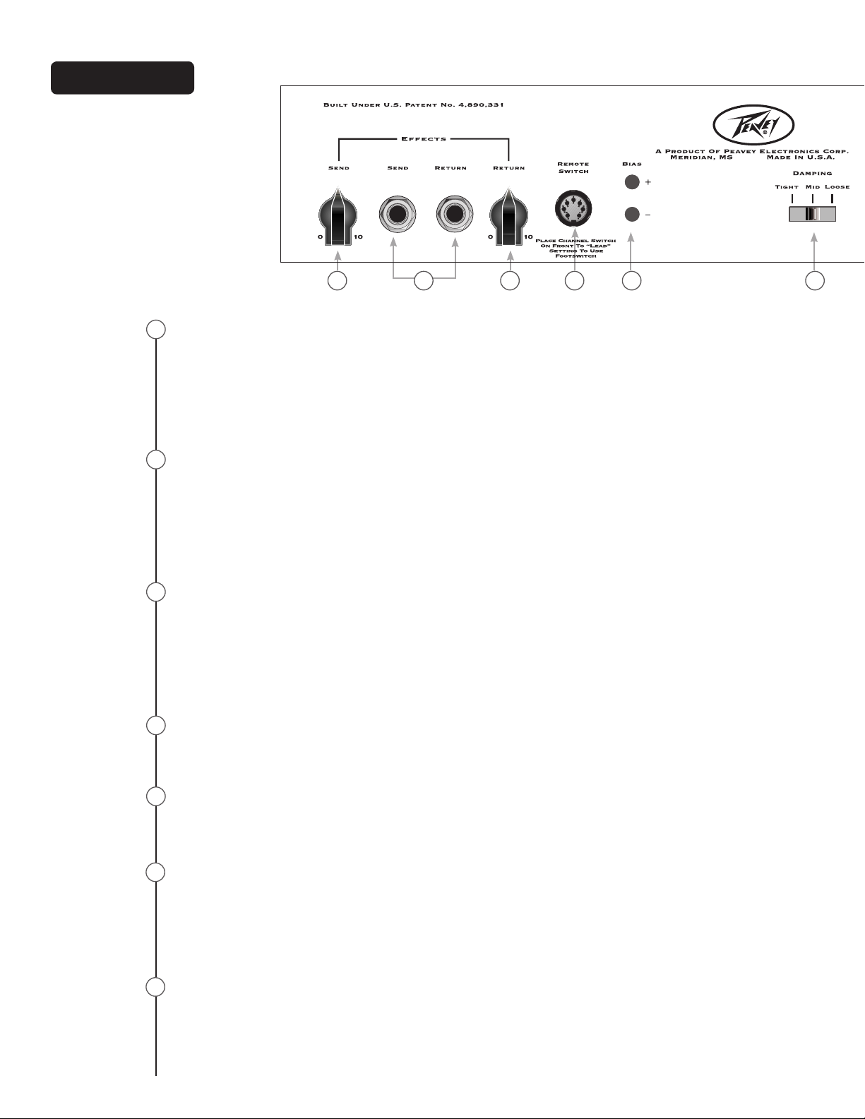
EFFECTS SEND LEVEL
1
This calibrated (0 – 10) control sets the level of signal being sent to external effects
and/or signal processors. Clockwise rotation increases the amount of signal being
sent; counterclockwise rotation decreases the amount. For the quietest operation,
the EFFECTS SEND LEVEL should be set as high as possible. Generally, the SEND and
RETURN levels should be set oppositely. If the EFFECTS SEND LEVEL is set low, the EFFECTS RETURN LEVEL (19) is set high to achieve unity gain. If volume boost is desired,
turn both controls to higher settings.
2
EFFECTS SEND / EFFECTS RETURN
These 1/4” mono (TS) jacks allow signal to be sent to and returned from external
effects and/or signal processors. Using shielded cables with 1/4” mono (TS) phone
plugs, patch from EFFECTS SEND to the input of the external device, and from the output of the external device to EFFECTS RETURN. Only devices that do not increase signal
gain should be used in this effects loop (chorus, delay, reverb, etc.). If the footswitch
is used, the EFFECTS SELECTOR (33) switch must be depressed to activate the effects
loop. See the FOOTSWITCH section of this manual for explanation of switch operation.
3
EFFECTS RETURN LEVEL
This calibrated (0 – 10) control sets the level of signal being returned from external effects and/or signal processors. Clockwise rotation increases the amount of signal being
returned; counterclockwise rotation decreases the amount. Again, SEND and RETURN
levels should be set oppositely, with the SEND level being high and the RETURN level
low to ensure the quietest operation. By setting both the Send and Return higher, you
can use the effects button on the footswitch as a boost if you aren’t using the effects
loop with effects.
REMOTE SWITCH
4
This seven-pin DIN connector is provided for the connection of the remote footswitch.
The footswitch cable should be connected before the amp is powered up. See the
FOOTSWITCH section of this manual for explanation of switch operation.
5
BIAS TEST TERMINALS
These terminals are provided to measure the bias of the amplier’s power tubes. A
knob behind the back panel grille allows for adjustment. Bias adjustment should only
be done by a qualied technician.
DAMPING SWITCH
6
This three-position switch allows adjustment of the amplier’s damping factor.
Damping is the ability of an amplier to control speaker cone motion after a signal
disappears. A high damping factor (TIGHT) reduces cone vibration quicker than a low
(LOOSE) factor. This switch works much like the Resonance and Presence controls
on other Peavey amps, if those controls were turned simultaneously. If the DAMPING
SWITCH is changed, the volume of the amp will also change and require re-adjustment.
7
CABINET IMPEDANCE SWITCH
This three-position switch allows appropriate selection of speaker cabinet impedance.
If two enclosures of equal impedance are used, the switch should be set to half the
individual value. For example, two 16-ohm enclosures necessitate an 8-Ohm setting,
while two 8-ohm enclosures would require a 4-ohm setting. Minimum speaker impedance is 4 ohms.
18
Page 19
11
7
8 9
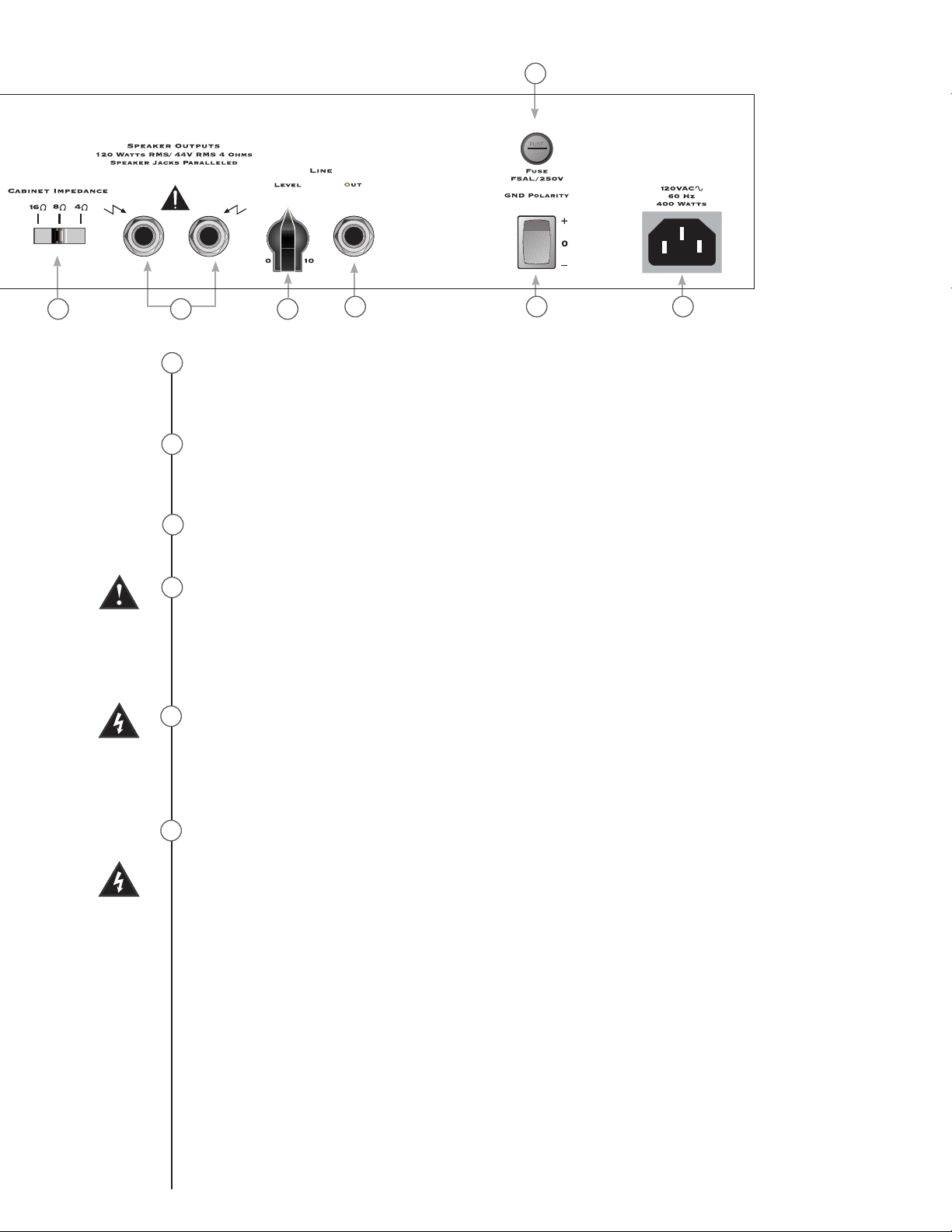
SPEAKER OUTPUTS
8
10 12 13
These paralleled 1/4” mono (TS) jacks are provided for the connection of speaker
enclosure(s). Again, minimum speaker impedance is 4 ohms. The CABINET IMPEDANCE
SWITCH (23) should be set to match the load of the speaker cabinet(s).
LINE OUT LEVEL
9
This control sets the level of signal being sent out of the LINE OUT (26) jack. It may be
used to balance the level of slave power amp/speaker systems driven from the LINE
OUT (26) to the level of cabinets driven from the SPEAKER OUTPUTS (24).
LINE OUT
10
This 1/4” mono (TS) jack provides a pre-power amp signal to drive another power amp/
speaker system while maintaining the amplier’s tone.
11
FUSE
A fuse is located within the cap of the fuse holder. This fuse must be replaced with one of
the same type and value to avoid damaging the amplier and voiding the warranty. If the
amp repeatedly blows the fuse, it should be taken to a qualied service center for repair.
WARNING: THE FUSE SHOULD ONLY BE REPLACED AFTER THE POWER CORD HAS
BEEN DISCONNECTED.
12
GROUND POLARITY SWITCH
This three-position, rocker-type switch should normally be placed in the center (0)
position. If hum or noise is noticed coming from the speaker enclosure(s), the switch
may be placed in the “+” or “-” position to minimize hum/noise. If changing the polarity does not alleviate the problem, consult your authorized Peavey dealer, the Peavey
factory, or a qualied service technician.
13
IEC MAINS CONNECTOR
This is a standard IEC power connector. An AC mains cord having the appropriate AC
plug and ratings for the intended operating voltage is included in the carton. The mains
cord should be connected to the amplier before connecting to a suitable AC outlet.
U.S DOMESTIC AC MAINS CORD
The mains cord supplied with the unit is a heavy-duty, 3-conductor type with a conventional 120 VAC plug with ground pin. If the outlet used does not have a ground pin,
a suitable grounding adapter should be used, and the third wire should be grounded
properly.
Never break off the ground pin on any equipment. It is provided for your safety.
NOTE: FOR UK ONLY
If the colors of the wires in the mains lead of this unit do not correspond with the colored markings identifying the terminals in your plug, proceed as follows: (1) The wire
that is colored green and yellow must be connected to the terminal that is marked by
the letter E, the earth symbol, colored green, or colored green and yellow. (2) The wire
that is colored blue must be connected to the terminal that is marked with the letter N
or the color black. (3) The wire that is colored brown must be connected to the terminal
that is marked with the letter L or the color red.
19
Page 20
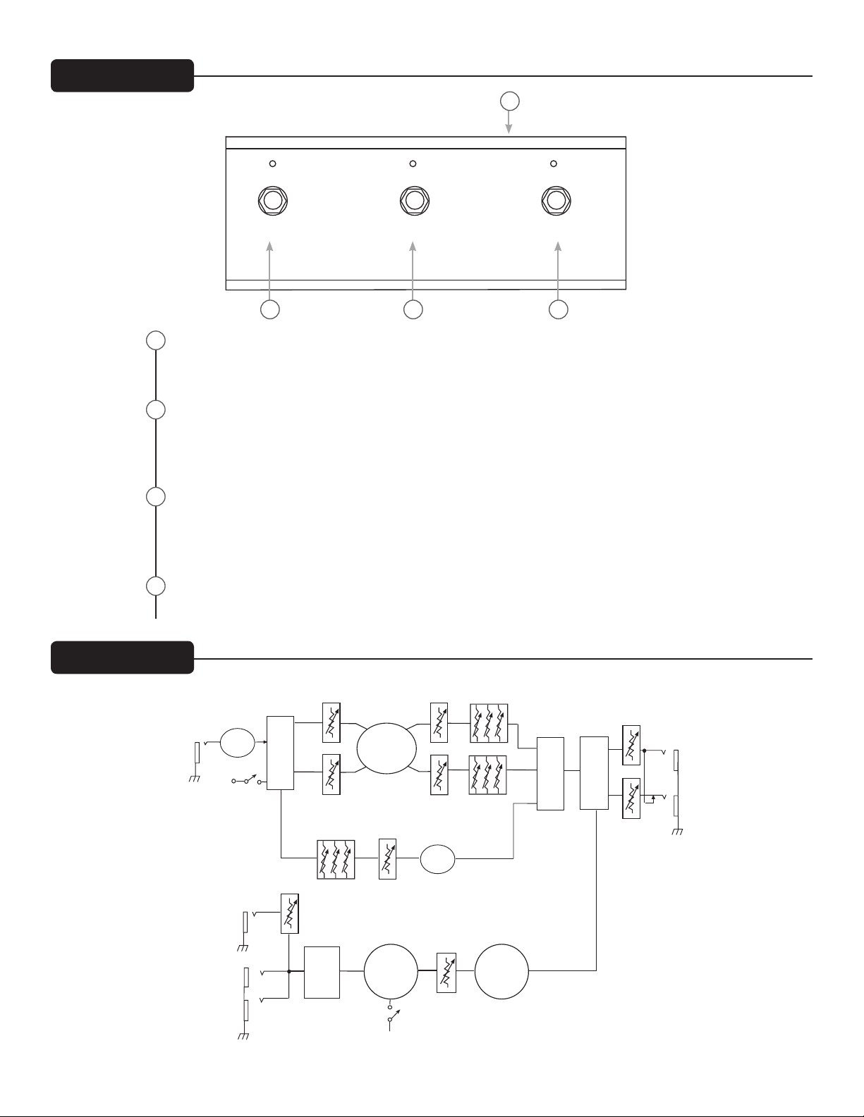
Footswitch
This block diagram shows the signal path within the unit. In order to thoroughly
understand the unit's functions, please study the block diagram carefully.
Block Diagram
TUBE
STAGE
SWITCH
LOGIC
RETURN
SEND
F.S.W
CHANNEL
ULTRA
TUBE
STAGES
SWITCH
LOGIC
FX LOOP
BYPA SS
EFFECTS
LOOP
VOICING
INPUT
BOT. BODY HAIR
BOT. BODY HAIR
ULTRA
CLEAN
TUBE
STAGE
CLEAN
BASS MID TREBLE
MASTER
VOLUME
TUBE
STAGES
TUBE
POWER AMP
IMPEDANCE
SWITCH
SEND
RETURN
LEVEL
LINE
OUT
CRUNCH
PRE
PRE
POST
POST
CRUNCH
PRE
DAMPING
SWITCH
4Ω 8 Ω 16 Ω
1
Lead Clean Effects
Lead/RhythM ByPass ByPass
2 3 4
CABLE CONNECTOR
1
This 7-pin DIN connector is provided for connecting the footswitch to the amplier REMOTE SWITCH (20) via the cable included in the carton. Connections at the switch and
the amplier should be made before the amp is powered up.
2
LEAD/RHYTHM SELECTOR
This switch selects between the Rhythm and Lead channels on the amplier. The adjacent LED will illuminate when the Lead/Lead channel is selected. When the LED is dark,
the Rhythm/Rhythm channel is selected. The CLEAN SELECTOR (32) must be in the
BYPASS mode to activate either the Rhythm or Lead channel.
Block Diagram
3
CLEAN SELECTOR
This switch selects the Clean channel and will activate regardless of the position of the
Lead/Rhythm SELECTOR (31). The adjacent LED will illuminate when the Clean channel is selected. This switch must be in the BYPASS position, indicated by a dark LED, in
order to utilize the Lead/Rhythm SELECTOR (31).
EFFECTS SELECTOR
4
This switch activates the amplier’s effects loop. The adjacent LED will illuminate when
the effects loop is active.
20
Page 21

Specifications
POWER AMPLIFIER SECTION:
Tubes:
Four EL34's with 12AX7 driver
Rated Power and Load:
120 W RMS into 16, 8, or 4 ohms
Power @ Clipping:
(Typically @ 5% THD, 1 kHz, 120 VAC line)
120 W RMS into 16, 8, or 4 ohms
Frequency Response:
±3 dB 50 Hz to 20 kHz @ 90 W RMS into 8 ohms
Hum and Noise:
Greater than 76 dB below rated power
Power Consumption:
Domestic: 400 W, 50/60 Hz, 120 VAC
Export: 400 W, 60 Hz, 220-230/240 VAC
PREAMP SECTION:
Tubes:
Three 12AX7
The following specs are measured @ 1 kHz with the controls preset
as follows:
Low and High EQ @ 10, Mid EQ @ 0
Rhythm and Lead Posts @ 10
Bass, Middle and Treble EQ @ 5
Effects Send @ 0
Effects Return @ 10
Master Level @ 5
Nominal Levels are with Pre Gain @ 5
Minimum Levels are with Pre Gain @ 10
Clean Channel:
Nominal Input Level: -20 dBV, 100 mV RMS
Minimum Input Level: -30 dBV, 30 mV RMS
Maximum Input Level: 0 dBV, 1.0 mV RMS
Rhythm Channel:
Nominal Input Level: -80 dBV, 0.1 mV RMS
Minimum Input Level: -90 dBV, 0.03 mV RMS
Lead Channel:
Nominal Input Level: -80 dBV, 0.1 mV RMS
Minimum Input Level: -90 dBV, 0.03 mV RMS
Effects Send:
Load Impedance: 47 k ohms or greater
Minimum Output: -10 dBV, 300 mV RMS
Maximum Output: 0 dBV, 1 V RMS
Effects Return:
Impedance: High-Z, 80 k ohms
Minimum Input Sensitivity: -10 dBV, 300 mV RMS
Maximum Input Sensitivity: 0 dBV, 1 V RMS
Line Output:
Load Impedance: 47 k ohms or greater
Adjustable Output: ±20 dBV, 0.1 V RMS-10 V RMS
REMOTE FOOTSWITCH:
Special 3-button unit with LED indicators (supplied)
System Hum and Noise @ Nominal Level:
(Clean channel, 20 Hz to 20 kHz unweighted)
Greater than 74 dB below rated power
(Special noise gate circuitry for Lead & Rhythm)
Equalization: (Clean channel only)
Custom Low, Mid, and High passive type EQ
Voicing: (Rhythm and Lead channels only)
Active Bass, Middle, and Treble EQ
Boost/Cut ±12 dB
Dimensions and Weight:
11.0" (279 mm) H x 26.5" (673 mm) W x 11.0" (279 mm) D
52 lbs. (23.6 kg)
21
Page 22

22
Page 23

El amplicador de guitarra Peavey 3120 simplemente hace shred. Desde su entrada de alta ganancia hasta los conectores
paralelos de salida de parlante, el Peavey 3120 no es para débiles. Este amplicador cuenta con características prácticas,
útiles para aplicaciones reales, que entregan una potencia de bulbo pura de 120 watts. Los canales de Ritmo y Solista cuentan
con controles de ganancia para ayudar a domar esta bestia mientras logra un sonido matador. El contorno del tono se logra a
través controles pasivos de Graves, Medios y Agudos del canal Limpio mientras que los canales de Ritmo y Solista utilizan los
controles activos de Graves, Medios y Agudos exclusivos de Peavey. Diseñado para funcionar perfectamente en cargas de 4, 8 o
16 ohm; los límites para adatar este monstruo a un bae son inimaginables.
CARACTERÍSTICAS
• Tres bulbos preamplificadores de 12AX7
• Cuatro bulbos amplificadores de potencia EL34 conducidos por un 12AX7
• Amplificador de potencia convertible para utilizar cuatro bulbos 6L6GC
• Lazo de efectos intercambiables con el pie con controles independientes de envío y retorno
• Interruptor de Damping (ajustado, medio, suelto)
• Circuito especial de la compuerta de ruido en los canales de Ritmo y Solista
• Salida de línea con control de nivel
• Interruptor de impedancia para bafle (4, 8, o 16 Ohm)
• Interruptores de alta potencia, standby y alternancia para la selección de canales
• Lámpara indicadora del estado de potencia clásica
312 0
ESPAÑOL
23
Page 24

Panel Frontal
1
2
3
4
5
6
7
INTERRUPTOR POWER
Este interruptor con palanca de dos posiciones aplica a la potencia de alimentación
de la unidad. La luz testigo del estado de encendido color ámbar (3) se iluminará
cuando éste interruptor se encuentre en la posición ENCENDIDO.
INTERRUPTOR STANDBY
Este interruptor con palanca de dos posiciones le permite al amplicador pon-
erse en modo STANDBY. Cuando se encuentra en posición STANDBY, los bulbos
permanecen calientes pero el amplicador no se encuentra en funcionamiento. Al
pasarlo a la posición ENCENDIDO, el amplicador se pone en modo activo.
LUZ DE ESTADO ENCENDIDO
Este indicador se ilumina cuando se proporciona alimentación al amplicador.
MASTER VOLUME
Este control congura el nivel de volumen general del amplicador. Una vez logrado el balance deseado entre los tres canales del amplicador, se puede aumentar
o disminuir todo el nivel de salida de la unidad girando este control. La rotación en
sentido a las agujas del reloj aumenta el nivel y la rotación en sentido opuesto a las
agujas del reloj disminuye el nivel.
TREBLE
Este control, tanto en el canal Rhythm como en el canal Lead, varía la respuesta
de alta frecuencia del amplicador. Es un control activo (tipo shelving) y permite
aumentar o reducir 15 dB.
MIDDLE
Este control, tanto en el canal Rhythm como en el canal Lead, varía la respuesta de
alta frecuencia media del amplicador. Es un control activo (tipo pico/muesca) y
permite aumentar o reducir 15 dB.
BASS (BAJOS)
Este control, tanto en el canal Rhythm como en el canal Lead, varía la respuesta
de baja frecuencia media del amplicador. Es un control activo (tipo shelving) y
permite aumentar o reducir 15 dB.
1 2 4 5 6 7
3
24
Page 25

8
9
10
11
12
13
14
15
VOLUME
Este control, en los tres canales, establece el nivel general de cada canal.
GAIN
Este control, tanto en el canal Rhythm como en el canal Lead, controla el nivel de
volumen de entrada del canal. Al girar este control en sentido a las agujas del reloj,
aumentará la cantidad de distorsión del preamplicador y del soporte.
LEDs DE ACTIVACIÓN DE CHANNEL
Estos indicadores muestran qué canal está activo. La activación del canal Lead
enciende el LED rojo; la activación del canal Rhythm enciende el LED amarillo; y la
activación del canal Clean enciende el LED verde.
TREBLE
Este control pasivo regula las frecuencias altas del canal Clean.
MIDDLE
Este control pasivo regula las frecuencias medias del canal Clean.
BASS
Este control pasivo regula las frecuencias bajas del canal Clean.
INPUT
Este conector de 1/4” está diseñado para aceptar la señal de salida de casi cualquier guitarra. La ganancia de entrada de la señal se puede ajustar con los controles
GANANCIA (9) (Sólo en los canales Rhythm y Lead).
INTERRUPTOR DE SELECCIÓN DE CHANNEL
Este interruptor con palanca de tres posiciones permite seleccionar entre los tres
canales del amplicador. La iluminación del LED (10) indica qué canal está activo.
También se puede cambiar de canal con el interruptor de pedal. Vea la sección
INTERRUPTOR DE PEDAL de este manual para observar la explicación sobre cómo
funciona el interruptor. El INTERRUPTOR DE SELECCIÓN DE CHANNEL debe estar en
posición Lead (Solista) para que el interruptor de pedal funcione correctamente.
9
11 12 13 14 15
10
8
25
Page 26

Panel Trasero
1
2
3
4
5
6
7
NIVEL DE EFFECTS SEND
Este control calibrado (0 a 10) establece el nivel de señal que se envía a los procesadores de
efectos y/o señales externas. Al girarlo en sentido de las agujas del reloj aumenta la cantidad de señal que se envía; al girarlo en sentido opuesto a las agujas del reloj, disminuye la
cantidad. Para un funcionamiento más rápido, el NIVEL EFFECTS SEND deberá establecerse lo
más alto posible. Generalmente los niveles SEND y RETURN deberán congurarse de manera
opuesta. Si el NIVEL EFFECTS SEND está congurado en bajo, el NIVEL EFFECTS RETURN (19)
estará congurado en alto, para lograr la ganancia unitaria. Si se desea aumentar el volumen,
congure ambos controles más altos.
EFFECTS SEND / EFFECTS RETURN
Estos conectores de 1/4” mono (TS) permiten que se envíe y retorne la señal de procesadores
de efectos y/o señal externa. Utilizando cables blindados en los enchufes de parlantes mono
(TS) de 1/4”, conecte EFFECTS SEND a la entrada del dispositivo externo y la salida del dispositivo externo a EFFECTS RETURN. En estos lazos de efecto sólo deberán utilizarse dispositivos
que no incrementen la ganancia de la señal (coro, delay, reverb digital, etc.). Si se utiliza el
interruptor de pedal, deberá liberarse el interruptor SELECTOR DE EFECTOS (33) para activar
el lazo de efectos. Observe la sección INTERRUPTOR DE PEDAL de este manual para obtener la
explicación del funcionamiento del interruptor.
NIVEL DE EFFECTS RETURN
Este control calibrado (0 a 10) establece el nivel de señal que retorna de los procesadores de
efectos y/o señales externas. Al girarlo en sentido a las agujas del reloj, aumenta la cantidad
de señal que se envía; al girarlo en sentido opuesto a las agujas del reloj, disminuye la cantidad. Nuevamente, los niveles SEND y RETURN deberán congurarse de manera opuesta, con el
nivel SEND alto y el nivel RETURN bajo para asegurar el funcionamiento más rápido. Congurando ambos niveles Send y Return más altos, puede utilizar el botón de efectos del interrup-
tor de pedal como potencia si no está utilizando el lazo de efectos con efectos.
REMOTE SWITCH
Se proporciona este conector DIN de siete pines para la conexión del interruptor de pedal
remoto. El cable del interruptor de pedal deberá conectarse antes de que se encienda el
amplicador. Observe la sección INTERRUPTOR DE PEDAL de este manual para observar la
explicación sobre cómo funciona el interruptor.
TERMINALES DE PRUEBA DE BIAS
Se proporcionan estos terminales para medir el bias de los bulbos de potencia del amplica-
dor. Hay una perilla detrás de la grilla del panel trasero para poder ajustar. El ajuste de bias
deberá realizarlo únicamente un técnico calicado.
DAMPING SWITCH
Este interruptor de tres posiciones permite ajustar el factor de amortiguación (damping) del
amplicador. Damping es la capacidad que tiene el amplicador de controlar el movimiento
del cono del parlante luego de que desaparezca una señal. Un factor de Damping alto (TIGHT)
reduce la vibración del cono más rápido que un factor bajo (LOOSE). Este interruptor fun-
ciona como los controles de Resonancia y Presencia en otros amplicadores Peavey, si esos
controles se giraran simultáneamente. Si se cambia el DAMPING SWITCH también cambiará el
volumen del amplicador y será necesario volver a ajustar.
INTERRUPTOR CABINET IMPEDANCE (INTERRUPTOR DE LA IMPEDANCIA DEL
BAFLE)
Este interruptor de tres posiciones permite la correcta selección de la impedancia del parlante
del bae. Si se utilizan dos cajas de igual impedancia, el interruptor deberá establecerse a
mitad del valor individual. Por ejemplo, dos cajas de 16 ohm necesitan una conguración de
8-Ohm, mientras que dos cajas de 8 Ohm requerirán de una conguración de 4 ohm. La impedancia mínima del parlante es de 4 Ohm.
1 3 4 652
26
Page 27

8
9
10
11
12
13
SPEAKER OUTPUTS
Se proporcionan estos conectores paralelos mono (TS) de 1/4” para la conexión de
la(s) caja(s) de parlantes. Nuevamente, la impedancia mínima del parlante es de 4
Ohm. El INTERRUPTOR DE IMPEDANCIA DEL BAFLE (23) deberá estar establecido de
manera que coincida con la carga del/de los parlante(s) del/de los bae(s).
LINE OUT LEVEL
Este control establece el nivel de señal que sale del conector LÍNEA DE SALIDA (26).
Debe utilizarse para balancear el nivel de los sistemas esclavos del amplicador de
energía/parlante que sale de la LÍNEA DE SALIDA (26) al nivel de los baes conducidos
desde las SALIDAS DE LOS PARLANTES (24).
LINE OUT
Este conector mono (TS) de 1/4” proporciona una señal de energía previa para conducir otro sistema de amplicador/parlante manteniendo el tono del amplicador.
FUSE
Se encuentra un fusible en la tapa del soporte de fusible. Eventualmente, este fusible
deberá cambiarse por uno del mismo tipo y valor para vitar dañar el amplicador y anular
la garantía. Si el amplicador quema el fusible repetidamente, deberá llevar el amplica-
dor a un centro de servicio técnico calicado para su reparación.
ADVERTENCIA: EL FUSE SÓLO DEBERÁ CAMBIARSE LUEGO DE HABER DESCONECTADO
EL CABLE DE ELECTRICIDAD.
INTERRUPTOR GROUND POLARITY
Este interruptor tipo rockero de tres posiciones generalmente deberá colocarse en la
posición central (0). Si nota zumbido o ruido proveniente de la(s) caja(s) de parlantes,
deberá colocar el interruptor en posición “+” o “-” para minimizar el zumbido/ruido. Si
al cambiar la polaridad no se mitiga el problema, consulte con su representante Peavey
autorizado, con la fábrica Peavey o con un técnico calicado.
CONECTOR DE LA FUENTE IEC
Este es un conector IEC estándar. Se incluye en la caja un cable fuente de CA con el
enchufe de CA apropiado y las clasicaciones de voltaje para el uso pretendido. Este
cable fuente deberá conectarse al amplicador antes de conectarlo a una salida de CA
apropiada.
CABLE DE ALIMENTACIÓN DE CA PARA USO EN LOS ESTADOS UNIDOS
El cable de alimentación suministrado con la unidad es del tipo de 3 conductores, para
trabajo severo, con un enchufe convencional de 120 VCA con espiga de tierra. Si el
tomacorriente no tiene alojamiento para la espiga de tierra, debe usarse un adaptador
adecuado de puesta a tierra, teniendo que conectarse a tierra adecuadamente el tercer
conductor.
Nunca rompa la pata de tierra en ningún equipo. Se proporciona para su seguridad.
7
11
10 12 13
8 9
27
Page 28

Interruptor de pedal
1
2
3
4
CONECTOR DE CABLES
Se proporciona este conector DIN de 7 pines para la conexión del interruptor de pedal
remoto al INTERRUPTOR REMOTO del amplicador (20) a través del cable incluido en
la caja. Las conexiones en el interruptor y en el amplicador deberán realizarse antes
de encender el amplicador.
SELECTOR LEAD/RHYTHM
Este interruptor selecciona los canales Rhythm y Lead del amplicador. El LED adjunto
se iluminará cuando está seleccionado el canal Lead/Lead. Cuando el LED está oscuro,
está seleccionado el canal Rhythm/Rhythm. El SELECTOR CLEAN (32) deberá estar en
modo BYPASS para activar el canal Rhythm o Lead.
SELECTOR CLEAN
Este interruptor selecciona el canal Clean y se activará cualquiera sea la posición del
SELECTOR Lead/Rhythm (31). El LED adjunto se iluminará cuando se seleccione el
canal Clean. Este interruptor deberá estar en la posición BYPASS, indicada por el LED
oscuro para utilizar el SELECTOR Lead/Rhythm (31).
SELECTOR EFFECTS
Este interruptor activa el lazo de los efectos del amplicador. El LED adjunto se iluminará cuando el lazo de efectos esté activo.
Lead/RhythM ByPass ByPass
Lead Clean Effects
1
2 3 4
Este diagrama del bloque muestra la ruta de la señal dentro de la unidad. Para comprender
en detalle el funcionamiento de la unidad, por favor, estudie el diagrama del bloque atentamente..
Block Diagram
TUBE
STAGE
SWITCH
LOGIC
RETURN
SEND
F.S.W
CHANNEL
ULTRA
TUBE
STAGES
SWITCH
LOGIC
FX LOOP
BYPASS
EFFECTS
LOOP
VOICING
INPUT
BOT. BODY HAIR
BOT. BODY HAIR
ULTRA
CLEAN
TUBE
STAGE
CLEAN
BASS MID TREBLE
MASTER
VOLUME
TUBE
STAGES
TUBE
POWER AMP
IMPEDANCE
SWITCH
SEND
RETURN
LEVEL
LINE
OUT
CRUNCH
PRE
PRE
POST
POST
CRUNCH
PRE
DAMPING
SWITCH
4Ω 8 Ω 16Ω
Diagrama del Bloque
28
Page 29

On peut dire que l’ampli guitare Peavey 3120 « déchire » tout bonnement. De l’entrée à haut gain aux sorties parallèles pour
haut-parleurs, le Peavey 3120 ne vous décevra pas. Cet amplicateur est doté de fonctions pratiques pour des congurations
précises délivrant 120 watts lampes à faire trembler le sol. Les canaux Rhythm et Lead sont dotés de commandes de gain pour
dompter la bête et obtenir le son qui tue. Le contour du son est réglable grâce aux commandes passives de fréquences basses,
mediums et aigues sur le canal Clean, tandis que les canaux Rhythm et Lead utilisent les commandes actives exclusives de
Peavey pour les basses, mediums et aigus. Conçu pour fonctionner aussi bien en charge 4, 8, que 16 ohms, ce monstre peut aller
avec n’importe quelle enceinte, selon votre imagination.
CARACTERISTIQUES
• Trois lampes pré-ampli 12AX7
• Quatre lampes EL34 de puissance pilotées par une 12AX7
• Amplificateur de puissance convertible pour quatre lampes 6L6GC
• Boucle d’effets commandée par pédalier avec commandes d’envoi et de retour indépendantes
• Interrupteur d’amortissement (serré, moyen, lâche)
• Circuit antiparasite spécial sur les canaux Rhythm et Lead
• Ligne de sortie avec contrôle de niveau
• Interrupteur d’impédance (4, 8, ou 16 Ohms)
• Interrupteurs de marche, veille et sélection de canaux pour usage intensif
• Témoin d’état de marche classique
312 0
FRANÇAIS
29
Page 30

Panneau avant
1
2
3
4
5
6
7
BOUTON POWER
Ce bouton va-et-vient commande l’alimentation électrique de l’appareil. Le témoin
d’état de couleur ambre (3) s’allume lorsque ce bouton est en position ON.
BOUTON STANDBY
Ce bouton va-et-vient permet de mettre l’ampli en mode VEILLE. En position
STANDBY, les lampes restent chaudes mais l’ampli n’est pas opérationnel. En position ON, ce bouton met l’ampli en mode actif.
TEMOIN D’ETAT DE MARCHE
Cet indicateur s’allume lorsque l’ampli est alimenté.
MASTER VOLUME
Cette commande règle le volume général de l’ampli. Une fois la balance souhaitée
entre les trois canaux, le niveau général de sortie de l’appareil peut être augmenté
ou diminué en tournant cette commande. Une rotation dans le sens horaire augmente le son ; une rotation dans le sens anti-horaire diminue le son.
TREBLE
Cette commande modie la réponse en hautes fréquences de l’ampli sur les canaux
Rhythm et Lead. C’est une commande active (de type rayonnage) autorisant 15 dB
de renforcement ou coupure.
MIDDLE
Cette commande modie la réponse en moyennes fréquences de l’ampli sur les
canaux Rhythm et Lead. C’est une commande active (écrêtage ou creusage) autorisant 15 dB de renforcement ou coupure.
BASS
Cette commande modie la réponse en basses fréquences de l’ampli sur les canaux
Rhythm et Lead. C’est une commande active (de type shelving) autorisant 15 dB de
renforcement ou coupure.
1 2 4 5 6 7
3
30
Page 31

8
9
10
11
12
13
14
15
VOLUME
Cette commande, sur les trois canaux, règle le niveau général sur chaque canal
respectivement.
GAIN
Cette commande, sur les canaux Rhythm et Lead, commande le niveau de volume
d’entrée du canal. La rotation dans le sens horaire augmente la distorsion et le
sustain du préampli.
DEL D’ACTIVATION CHANNEL
Ces témoins indiquent quel canal est actif. Le témoin rouge indique l’activation du
canal Lead ;le témoin jaune pour le canal Rhythm ; et le témoin vert pour le canal
Clean.
TREBLE
Cette commande passive régule les hautes fréquences pour le canal Clean.
MID
Cette commande passive régule les fréquences moyennes pour le canal Clean.
BASS
Cette commande passive régule les fréquences basses pour le canal Clean.
INPUT
Cette prise d’entrée 1/4” (6,35mm) est conçue pour aller avec le signal de sortie de
la plupart des guitares. Le gain de signal d’entrée peut être ajusté avec les com-
mandes GAIN (9) (canaux Rhythm et Lead uniquement).
SELECTEUR CHANNEL
Ce bouton à trois positions permet de sélectionner l’un des trois canaux de
l’ampli. La DEL (10) indique quel canal est actif. Le changement de canal peut aussi
s’effectuer avec le pédalier. Voir la section PEDALIER dans ce guide pour les détails
de fonctionnement. L’INTERRUPTEUR DE SELECTION CHANNEL doit être en position
Lead pour pouvoir faire fonctionner le pédalier.
9
11 12 13 14 15
10
8
31
Page 32

Panneau arrière
1
2
3
4
5
6
7
NIVEAU EFFECTS SEND
Cette commande calibrée (0 -10) règle le niveau de signal envoyé aux effets externes
et/ou processeurs. La rotation dans le sens horaire augmente la quantité de signal
envoyé ; la rotation dans le sens inverse la diminue. Pour être plus tranquille, il vaut
mieux régler le NIVEAU EFFECTS SEND le plus haut possible. Généralement, les niveaux
SEND et RETURN doivent être réglés de façon opposée. Si le NIVEAU EFFECTS SEND
est bas, le NIVEAU EFFECTS RETURN (19) doit être haut pour avoir un gain unié. Pour
renforcer le volume, tourner les deux commandes vers le plus haut réglage.
EFFECTS SEND / EFFECTS RETURN
Cette prise mono (TS) 1/4” (6,35mm) permet d’envoyer le signal aux effets externes
et/ou processeurs de signal et de l’en faire revenir. Raccorder des câbles torsadés
blindés à prises mono (TS) 1/4”, de EFFECTS SEND à l’entrée d’un appareil externe, et
de la sortie de l’appareil externe à EFFECTS RETURN. N’utiliser que des appareils qui
n’augmentent pas le gain de signal pour cette boucle d’effets (chorus, délai, réverbération, etc.). Pour utiliser le pédalier, enfoncer le sélecteur d’effets EFFECTS SELECTOR
(33) pour activer la boucle d’effets. Voir la section PEDALIER dans ce guide pour les
détails de fonctionnement.
NIVEAU EFFECTS RETURN
Cette commande calibrée (0 -10) règle le niveau de signal retourné depuis les effets
externes et/ou processeurs de signal. La rotation dans le sens horaire augmente la
quantité de signal retourné ; la rotation dans l’autre sens la diminue. Encore une fois,
les niveaux SEND et RETURN doivent être réglés de façon opposée, avec le niveau
SEND élevé et le niveau RETURN bas pour plus de tranquillité dans le fonctionnement.
Si Send et Return sont élevés, le bouton d’effets du pédalier peut être utilisé comme
renforcement si l’utilisateur ne se sert pas de la boucle d’effets.
REMOTE SWITCH
Ce connecteur DIN à sept points permet de brancher le pédalier. Le câble de ce dernier
doit être branché avant l’activation de l’ampli. Voir la section PEDALIER dans ce guide
pour les détails de fonctionnement.
BORNES DE TEST BIAS
Ces bornes permettent de mesurer la polarisation des lampes de puissance de l’ampli.
Un bouton derrière la grille du panneau arrière en permet le réglage. Le réglage de
polarisation ne doit être fait que par un technicien expérimenté.
DAMPING SWITCH
Ce bouton à trois positions permet de régler le facteur d’amortissement de
l’amplicateur. L’amortissement est la capacité d’un amplicateur à commander le
mouvement de la membrane du haut-parleur après disparition d’un signal. Un facteur
d’amortissement élevé (TIGHT) réduit la vibration de la membrane plus rapidement
qu’un facteur plus bas (LOOSE). Cet interrupteur fonctionne plutôt comme les com-
mandes de Résonnance et Présence sur les autres amplis Peavey, si ces commandes
sont tournées simultanément. Si le bouton DAMPING SWITCH est changé, le volume de
l’ampli change également et requiert un nouvel ajustement.
BOUTON CABINET IMPEDANCE
Ce bouton à trois positions permet une sélection appropriée de l’impédance acoustique de l’enceinte. Si deux enceintes d’égale impédance sont utilisées, le bouton doit
être sur la moitié de la valeur individuelle. Par exemple, deux enceintes acoustiques de
16 ohms nécessitent un réglage de 8 0hms, et deux enceintes de 8 ohms demandent
un réglage de 4 ohms. L’impédance minimale est de 4 ohms.
1 3 4 652
32
Page 33

8
9
10
11
12
13
SPEAKER OUTPUTS
Ces prises mono (TS) 1/4” parallèles permettent de brancher une/des enceinte(s)
acoustique(s). A nouveau, l’impédance minimale est de 4 ohms. Le bouton
d’impédance acoustique CABINET IMPEDANCE SWITCH (23) doit être réglé de façon à
correspondre à la charge des enceintes.
LINE OUT LEVEL
Cette commande règle le niveau de signal envoyé par la prise LINE OUT (26). Elle
permet d’équilibrer le niveau des systèmes ampli esclave/haut-parleur passant par la
sortie de ligne LINE OUT (26) au niveau des enceintes passants par les SORTIES HAUTPARLEUR (24).
LINE OUT
Cette prise mono (TS) 1/4” donne un signal pré-ampli de puissance pour guider un
autre système d’ampli/haut-parleur tout en maintenant la tonalité de l’amplicateur.
FUSE
Un fusible est placé dans le cache du support à fusible. Il doit être remplacé par un autre
de mêmes type et valeur an d’éviter d’endommager l’ampli et d’annuler la garantie. Si
l’ampli brûle son fusible de façon répétée, il doit être porté à un centre de réparation pour
inspection.
AVERTISSEMENT: LE FUSIBLE NE DOIT ETRE REMPLACE QUE LORSQUE LE CORDON
ELECTRIQUE EST DEBRANCHE.
BOUTON GROUND POLARITY
Ce bouton à bascule à trois positions doit normalement être en position centrale (0). En
cas de bourdonnement ou bruit venant de la/des enceinte(s), ce bouton peut être mis
en position “+” ou “-” pour diminuer ces perturbations. Si le changement de polarité ne
résout pas le problème, consulter un vendeur Peavey, l’usine Peavey ou un technicien
expérimenté.
CONNECTEUR D’ALIMENTATION PRINCIPALE CEI
C’est un connecteur de puissance CEI standard. Un cordon électrique CA ayant une
prise CA et des caractéristiques correctes pour la tension correspondant au fonctionnement concerné, est fourni avec l’appareil. Le cordon électrique doit être branché à
l’ampli avant d’être branché dans la prise d’alimentation.
CORDON ELECTRIQUE CA DOMESTIQUE U.S
Le cordon électrique fourni avec l’appareil est un cordon résistant de type 3 conducteurs avec prise à la terre conventionnelle 120 V CA. Si la prise d’alimentation utilisée
ne comprend pas de che à la terre, il faut utiliser un adaptateur à la terre adéquat, et
le troisième l doit être correctement conduit à la terre.
Ne jamais casser la tige de terre sur aucun équipement. Elle est là pour votre sécurité.
7
11
10 12 13
8 9
33
Page 34

Pédalier
1
2
3
4
CONNECTEUR DE CABLE
Ce connecteur DIN à 7 points permet de brancher le pédalier à l’interrupteur à distance
REMOTE SWITCH (20) de l’ampli via le câble fourni. Les branchements à le pédalier et à
l’ampli doivent être effectués avant d’allumer l’ampli.
SELECTEUR LEAD/RHYTHM
Ce bouton permet de sélectionner entre les canaux Rhythm et Lead sur l’ampli. La DEL
adjacente s’allume lorsque le canal Lead/Lead est sélectionné. Lorsque le témoin est
éteint, c’est le canal Rhythm/Rhythm qui est sélectionné. Le SELECTEUR CLEAN (32)
doit être en mode BYPASS pour activer le canal Rhythm ou le canal Lead.
SELECTEUR CLEAN
Ce bouton sélectionne le canal Clean et l’active quelle que soit la position du SELECT-
EUR Lead/Rhythm (31). La DEL adjacente s’allume lorsque le canal Clean est sélectionné. Ce bouton doit être en position BYPASS, indiquée par une DEL éteinte, pour pouvoir
utiliser le SELECTEUR Lead/Rhythm (31).
SELECTEUR EFFECTS
Ce bouton active la boucle d’effets de l’ampli. La DEL adjacente s’allume lorsque la
boucle d’effets est active.
Lead/RhythM ByPass ByPass
Lead Clean Effects
1
2 3 4
Ce schéma fonctionnel indique le passage du signal dans l’appareil.
Block Diagram
TUBE
STAGE
SWITCH
LOGIC
RETURN
SEND
F.S.W
CHANNEL
ULTRA
TUBE
STAGES
SWITCH
LOGIC
FX LOOP
BYPASS
EFFECTS
LOOP
VOICING
INPUT
BOT. BODY HAIR
BOT. BODY HAIR
ULTRA
CLEAN
TUBE
STAGE
CLEAN
BASS MID TREBLE
MASTER
VOLUME
TUBE
STAGES
TUBE
POWER AMP
IMPEDANCE
SWITCH
SEND
RETURN
LEVEL
LINE
OUT
CRUNCH
PRE
PRE
POST
POST
CRUNCH
PRE
DAMPING
SWITCH
4Ω 8 Ω 16Ω
Pour bien comprendre le fonctionnement de l’appareil,
étudier attentivement ce schéma
Schéma fonctionnel
34
Page 35

Der Peavey 3120 Gitarrenverstärker ist wildes Monster. Vom High Gain Eingang bis zu den Lautsprecher Ausgangsbuchsen, ist
der Peavey 3120 durch und durch nichts für schwache Herzen. Dieser Verstärker ist mit vielen praktischen Funktionen bestückt,
die bis zu 120 Watt reine Röhrenleistung liefern, welches die Erde erzittern lässt. Die Rhythmus- und Lead Kanäle besitzen
Gainregler, um dieses wilde Tier zu zähmen, während es einen wahren Killersound produziert. Die Klangregelung wird im
Clean Kanal über passive Regler für Bass, Mitten und Höhen geregelt, während die Rhythmus- und Lead Kanäle, aktive Bass-,
Mitten- und Höhen-Regler für die Klangformung nutzen. Eine umschaltbare Anpassung sorgt für den richtigen Anschluss an eine
passende Lautsprecherbox und ein globaler Masterregler zügelt das Biest.
FEATURES
• Drei 12AX7 Vorverstärkerröhren
• Vier EL34 Endverstärkerröhren, die von einer 12AX7 angetrieben werden
• Die Endstufe ist für die Verwendung von bis zu vier 6L6GC Röhren konvertierbar
• Fußschaltbare Effektschleife mit unabhängigen Send- und Return-Reglern
• Dämpfungsschalter (tight, medium, loose)
• Spezielle Noisegate Schaltung für Rhythmus- und Lead Kanäle
• Line-Ausgang mit Pegelregler
• Lautsprecher-Impedanzschalter (4, 8 oder 16 Ohm)
• „Heavy Duty“ Kippschalter für Netz, Stand-by- und Kanalwahl
• Klassische Betriebsanzeige
312 0
DEUTSCH
35
Page 36

Vorderseite
1
2
3
4
5
6
7
POWER-SCHALTER
Dieser Zweiweg-Kippschalter versorgt den Verstärker mit Strom. Die Betriebsan-
zeige (3) leuchtet, wenn der Schalter auf ON steht.
STANDBY-SCHALTER
Mit diesem Kippschalter wird der Verstärker in den STANDBY-Betrieb versetzt, d.h.
die Betriebstemperatur der Röhren bleibt erhalten, aber der Verstärker ist inaktiv.
Soll in den aktiven Betrieb gewechselt werden, einfach den Schalter in die ON
Position schalten.
BETRIEBSANZEIGE
Diese Anzeige leuchtet, wenn der Verstärker mit Strom versorgt wird.
MASTER VOLUME
Mit diesem Regler wird die Gesamtlaufstärke des Verstärkers eingestellt. Sobald
man die drei Kanäle wunschgemäß justiert hat, kann mit diesem Regler die Gesamtlautstärke des Verstärkers eingestellt werden. Drehen im Uhrzeigersinn erhöht
den Pegel; Drehen gegen den Uhrzeigersinn verringert den Pegel.
TREBLE
Mit diesem Regler werden die hohen Frequenzen auf den Rhythm und LeadKanälen der Endstufe eingestellt. Es handelt sich um einen aktiven Regler und er
lässt eine Anhebung oder Absenkung von 15 dB zu.
MIDDLE
Mit diesem Regler werden die mittleren Frequenzen auf den Rhythm und LeadKanälen der Endstufe eingestellt. Es handelt sich um einen aktiven Regler und er
lässt eine Anhebung oder Absenkung von 15 dB zu.
BASS
Mit diesem Regler werden die tiefen Frequenzen auf den Rhythm und Lead-Kanälen
der Endstufe eingestellt. Es handelt sich um einen aktiven Regler und er lässt eine
Anhebung oder Absenkung von 15 dB zu.
1 2 4 5 6 7
3
36
Page 37

8
9
10
11
12
13
14
15
VOLUME
Mit diesem Regler wird bei allen drei Kanälen die Gesamtlaufstärke des entsprechenden Kanals eingestellt.
GAIN
Dieser Regler steuert den Eingangslautstärkepegel auf den Rhythm und LeadKanälen. Durch Drehen dieses Reglers im Uhrzeigersinn erhöhen sich der Verzerrungsgrad und die Komprimierung des Signals im Vorverstärker.
CHANNEL LED’s
Diese LED’s zeigen an, welcher Kanal aktiv ist. Bei Lead-Kanalaktivierung leuchtet
die rote LED, bei Aktivierung des Rhythm-Kanals leuchtet die gelbe LED und bei
Aktivierung des Clean-Kanals leuchtet die grüne LED auf.
TREBLE
Mit diesem Regler können die Höhen des Clean-Kanals eingestellt werden.
MID
Mit diesem Regler können die Mitten des Clean-Kanals eingestellt werden.
BASS
Mit diesem Regler können die Bässe des Clean-Kanals eingestellt werden.
INPUT
Über diese 6,35 mm Klinkenbuchse wird das Instrument mit dem Verstärker verbunden. Die Eingangssignalverstärkung kann mit dem GAIN-Regler (9) eingestellt
werden (nur Rhythm- und Lead-Kanäle).
CHANNEL-WAHLSCHALTER
Dieser 3-fach Wahlschalter ermöglicht die Auswahl zwischen den drei Kanälen des
Verstärkers. Eine LED (10) zeigt den jeweilig aktiven Kanal an. Das Umschalten
zwischen den Kanälen kann auch mittels Fußschalter erfolgen. Zur Erklärung der
Schalterfunktion bitte im Fußschalter-Abschnitt dieser Bedienungsanleitung nachschlagen. Der CHANNEL-WAHLSCHALTER muss auf die Lead Position eingestellt
werden, damit der Fußschalter aktiviert wird.
9
11 12 13 14 15
10
8
37
Page 38

Rückseite
1
2
3
4
5
6
7
EFFECTS SEND-LEVEL
Dieser kalibrierte (0 bis 10) Regler stellt den Signalpegel ein, der an externe Effekt- und/oder
Signalprozessoren gesendet wird. Drehen im Uhrzeigersinn erhöht die Intensität des zu send-
enden Signals; Drehen gegen den Uhrzeigersinn verringert die Stärke des Signals. Für die leis-
este Arbeitsweise sollte der EFFECTS SEND REGLER so hoch wie möglich eingestellt werden.
Generell sollten die SEND und RETURN Regler entgegengesetzt eingestellt werden. Wenn
der EFFECTS SEND REGLER niedrig eingestellt ist, stellen Sie den EFFECTS RETURN REGLER
(19) hoch ein, um eine neutrale Einstellung zu erreichen. Wenn eine Erhöhung der Lautstärke
gewünscht wird, schalten Sie beide Regler in eine höhere Einstellung.
EFFECTS SEND / EFFECTS RETURN
Diese 6,35 mm Klinkenbuchsen (mono) ermöglichen das Senden und Empfangen der Signale
von externen Effekt- und/oder Signalprozessoren. Mit abgeschirmten Klinkenkabeln wird das
externe Effektgerät von EFFECTS SEND mit dem Eingang des externen Geräts und der Ausgang
des externen Geräts zurück mit EFFECTS RETURN verbunden. Nur Geräte, welche die Signalverstärkung nicht erhöhen, sollten in diesem Effekteinschleifweg (Chorus, Delay, Reverb usw.)
verwendet werden. Für eine Aktivierung des Effekteinschleifwegs per Fußschalter muss der
EFFECTS-SELECTOR Schalter (33) gedrückt werden. Zur Erklärung der Schalterfunktion bitte im
Fußschalter-Abschnitt dieser Bedienungsanleitung nachschlagen.
EFFECTS RETURN-LEVEL
Dieser kalibrierte (0 bis 10) Regler stellt den Signalpegel ein, der von externen Effekt- und/oder
Signalprozessoren zurückgesendet wird. Drehen im Uhrzeigersinn erhöht das Signal; Drehen
gegen den Uhrzeigersinn verringert das Signal. Auch hier sollten die SEND und RETURN Regler
bei hoch eingestellten SEND- und niedrig eingestellten RETURN-Regler gegenläug eingestellt
werden, um die leiseste Arbeitsweise zu gewährleisten. Indem sowohl Send als auch Return
eingestellt werden, können Sie den Effektschalter am Fußschalter als Verstärker verwenden,
wenn Sie den Effekteinschleifweg nicht mit Effekten verwenden.
REMOTE SWITCH
Diese siebenpolige DIN Buchse ist für den Anschluss des Fußschalters gedacht. Das Fußschalterkabel muss vor dem Einschalten des Verstärkers angeschlossen werden. Zur Erklärung der
Schalterfunktion bitte im Fußschalter Abschnitt dieser Bedienungsanleitung nachschlagen.
BIAS TEST-ANSCHLÜSSE
Diese Anschlüsse sind zum Messen des Bias der Verstärker-Endstufenröhren gedacht. Ein
Regler hinter dem Grill auf der Rückseite ermöglicht die Einstellung. Die Anpassung des Bias
darf nur von einem Fachmann ausgeführt werden.
DAMPING SWITCH
Dieser 3-fach Schalter ermöglicht die Einstellung des Dämpfungsfaktors des Verstärkers.
Die Dämpfung ist die Fähigkeit eines Verstärkers, die Schwingungen der Lautsprechermem-
brane zu steuern, nachdem das Signal verschwunden ist. Ein hoher Dämpfungsfaktor (TIGHT)
reduziert die Schwingungen der Membrane schneller als ein niedriger (LOOSE) Faktor. Wenn
diese Regler gleichzeitig eingeschaltet wurden, funktioniert dieser Schalter ähnlich wie die
Resonanz- und Presence-Regler bei anderen Peavey Verstärkern. Wenn der DAMPING SWITCH
verändert wurde, wird die Lautstärke des Verstärkers auch verändert und erfordert eine Nachjustierung.
CABINET IMPEDANCE-SCHALTER
Mit diesem 3-fach Schalter kann die geeignete Impedanz der Lautsprecherboxen
ausgewählt werden. Wenn zwei Boxen mit gleicher Impedanz verwendet werden, sollte
der Schalter auf die Hälfte der jeweiligen Impedanz gestellt werden. So benötigen z.
B. zwei 16 Ohm Boxen eine 8 Ohm Einstellung oder zwei 8 Ohm Boxen eine 4 Ohm
Einstellung. Die minimale Lautsprecherimpedanz bei voller Leistung beträgt 4 Ohm.
1 3 4 652
38
Page 39

8
9
10
11
12
13
SPEAKER OUTPUTS
Diese parallel geschalteten 6,35 mm Klinkenbuchsen (mono) sind für den Anschluss
der Lautsprecherbox(en) gedacht. Die minimale Lautsprecherimpedanz beträgt 4 Ohm
bei voller Leistung. Der CABINET IMPEDANCE SCHALTER (23) sollte so eingestellt sein,
dass er der Impedanz der Lautsprecherbox(en) entspricht.
LINE OUT LEVEL
Dieser Regler stellt den Signalpegel ein, der an der LINE OUT (26) Buchse anliegt. Er
kann dazu verwendet werden, um den Pegel der Slave-Leistungsverstärker/Lautsprecher-Systeme, die von LINE OUT (26) versorgt werden, an den Pegel von Lautsprecherboxen an den LAUTSPRECHER AUSGÄNGEN (24) anzupassen.
LINE OUT
Diese 6,35 mm Klinkenbuchsen (mono) liefern ein Vorverstärkersignal, um ein weiteres
Endstufen/Lautsprechersystem unter Beibehaltung des Verstärkerklangs zu versorgen.
FUSE
Die Sicherung bendet sich in der Kappe des Sicherungshalters. Diese Sicherung muss
mit einer Sicherung vom selben Typ und mit gleichem Wert ersetzt werden, damit der
Verstärker nicht beschädigt wird und die Garantie erlischt. Wenn die Sicherung des
Verstärkers immer wieder durchbrennt, sollte der Verstärker von einem qualizierten
Kundenservice-Center überprüft werden.
WARNUNG: VOR DEM WECHSELN DER SICHERUNG NETZSTECKER ZIEHEN.
GROUND POLARITY-SCHALTER
Dieser 3-fach Kippschalter sollte normalerweise in die mittlere Stellung(0) geschaltet
werden. Wenn die Lautsprecher brummen oder rauschen, kann der Schalter zum
Verringern des Brummen/Rauschens in die Stellung „+“ oder „-“ eingestellt werden.
Wenn ein Polaritätswechsel das Problem nicht verringert, wenden Sie sich an Ihren
autorisierten Peavey Händler, direkt an Peavey oder an einen qualizierten Service-
Techniker.
IEC-STROMANSCHLUSS
Dies ist ein Standard IEC-Stecker. Ein Stromkabel ist natürlich im Lieferumfang enthalten. Das Stromkabel sollte am Verstärker angeschlossen sein, bevor es mit einer
Steckdose verbunden wird.
NETZKABEL FÜR US-HAUSHALTE - CAN BE DELETED IN GERMAN MANUAL
Das mit dem Gerät mitgelieferte Netzkabel besitzt einen herkömmlichen, 3-adrigen,
120V Hochleistungs-Netzstecker mit Schutzkontakt. Wenn die Steckdose keinen
Schutzkontakt besitzt, müssen Sie einen geeigneten Erdungsadapter verwenden und
die dritte Litze muss ordnungsgemäß geerdet werden.
Niemals den Erdungskontakt eines Geräts unterbrechen. Er dient Ihrer Sicherheit.
7
11
10 12 13
8 9
39
Page 40

Fußschalter
1
2
3
4
KABELANSCHLUSS
Diese siebenpolige DIN Buchse ist für den Anschluss des Fußschalters mittels des mitgelieferten Kabels an den REMOTE-SCHALTER (20) des Verstärkers gedacht Der Anschlüsse an
den Schalter und den Verstärker müssen vor dem Einschalten des Verstärkers erfolgen.
LEAD/RHYTHM-WAHLSCHALTER
Dieser Schalter schaltet zwischen Rhythm- und Lead-Kanälen am Verstärker um. Wenn der
Lead/Lead-Kanal gewählt wurde, leuchtet die entsprechende LED auf. Wenn die LED nicht
leuchtet, wurde der Rhythm/Rhythm-Kanal gewählt. Der CLEAN-WAHLSCHALTER (32) muss
sich im BYPASS-Modus benden, um entweder den Rhythm oder Lead-Kanal zu aktivieren.
CLEAN-WAHLSCHALTER
Dieser Schalter wählt den Clean-Kanal und wird unabhängig von der Stellung des Lead/
Rhythm-WAHLSCHALTERS (31) aktiviert. Wenn der Clean-Kanal gewählt wurde, leuchtet die
entsprechende LED auf. Damit der Lead/Rhythm-WAHLSCHALTER (31) verwendet werden
kann, muss sich dieser Schalter in der BYPASS-Stellung benden. Das wird durch die nicht
leuchtende LED angezeigt.
EFFECTS-WAHLSCHALTER
Dieser Schalter aktiviert den Effekteinschleifweg des Verstärkers. Wenn der Effekteinschleifweg aktiviert ist, leuchtet die entsprechende LED auf.
Lead/RhythM ByPass ByPass
Lead Clean Effects
1
2 3 4
Das Blockschaltbild zeigt den Signalweg innerhalb des Geräts.Um die Funktionen des
Geräts vollständig zu verstehen, schauen Sie sich bitte das Blockschaltbild sorgfältig an..
Block Diagram
TUBE
STAGE
SWITCH
LOGIC
RETURN
SEND
F.S.W
CHANNEL
ULTRA
TUBE
STAGES
SWITCH
LOGIC
FX LOOP
BYPASS
EFFECTS
LOOP
VOICING
INPUT
BOT. BODY HAIR
BOT. BODY HAIR
ULTRA
CLEAN
TUBE
STAGE
CLEAN
BASS MID TREBLE
MASTER
VOLUME
TUBE
STAGES
TUBE
POWER AMP
IMPEDANCE
SWITCH
SEND
RETURN
LEVEL
LINE
OUT
CRUNCH
PRE
PRE
POST
POST
CRUNCH
PRE
DAMPING
SWITCH
4Ω 8 Ω 16Ω
Blockschaltbild
40
Page 41

Questo nuovissimo amplicatore per chitarra di Peavey è letteralmente devastante. Con il suo ingresso high-gain e le uscite
speaker in parallelo, il Peavey Electronics 3120 non è davvero per i deboli di cuore. Progettato per i moderni chitarristi che
sanno ciò che vogliono, questo amplicatore punta alla praticità assoluta, che lo rendono perfetto da usare in concerto.
Nonostante i suoi dirompenti 120 Watt di pura potenza valvolare, il 3120 resta facile da controllare, grazie alla manopola del
Master Volume e ad un controllo di volume separato per ognuno dei tre canali. I canali Rhythm e Lead hanno anche un controllo
di gain, che permette di dominare la belva anche con il suono più micidiale. L’equalizzazione del canale Clean è costituita da
controlli passivi di bassi, medi ed alti, mentre quella dei canali Rhythm e Lead si basa su esclusivi controlli attivi di bassi, medi
ed alti appositamente concepiti da Peavey. Progettato per funzionare altrettanto bene con carichi di 4, 8 o 16 Ohm, è possibile
accoppiare questo mostro a qualsiasi tipo di cassa. Grazie al loop effetti e alla possibilità di selezionare i canali da pedale, il
3120 vi lascia tenere le mani sulla chitarra – e lo sguardo perso nei sogni.
CARATTERISTICHE
• Tre valvole di preamplificazione 12AX7
• Quattro valvole di potenza EL34 pilotate da una 12AX7
• Finale predisposto all’uso di quattro valvole 6L6GC
• Loop effetti attivabile da pedale, con controlli separati per mandata e ritorno effetti
• Damping (smorzamento) switch (Tight, Medium, Loose)
• Special Noise Gate circuitry su canali Rhythm e Lead
• Uscita di linea (Line Out) con controllo di livello
• Selettore impedenza casse (4, 8 o 16 Ohm)
• Robusti interruttori di accensione, standby e selezione canali
• Classico indicatore di accensione a lampadina
• Manopole controlli chicken-head custom Peavey
312 0
ITALIANO
41
Page 42

Pannello Anteriore
1
2
3
4
5
6
7
INTERRUTTORE DI ACCENZIONE
Questo interruttore a due posizioni permette di accendere l’amplicatore. Quando
è in posizione ON (acceso), l’indicatore luminoso ambra POWER STATUS (3) si accende.
INTERRUTTORE STANDBY
Questo interruttore a due posizioni consente di mettere l’amplicatore in STANDBY. In questo stato, le valvole rimangono sotto tensione, ma l’amplicatore non
suona. Passando alla posizione ON, l’amplicatore viene riattivato.
INDICATORE LUMINOSO ALIMENTAZIONE
Questo indicatore si accende quando l’alimentazione è alimentata all’amplicatore.
MASTER VOLUME
Questo controllo permette di regolare il volume generale dell’amplicatore. Una
volta trovato il bilanciamento ottimale fra i tre canali dell’amplicatore, si può
usare questo controllo per regolare il livello di uscita generale. Ruotate la manopola in senso orario per aumentare il livello, ruotatela in senso antiorario per
diminuirlo.
TREBLE
Questo controllo, nei canali Rhythm e Lead, permette di modicare la risposta
dell’amplicatore sulle frequenze alte. Si tratta di un controllo attivo (di tipo shelving) che consente di ottenere un’enfasi o un’attenuazione di ±15 dB.
MIDDLE
Questo controllo, nei canali Rhythm e Lead, permette di modicare la risposta
dell’amplicatore sulle frequenze medie. Si tratta di un controllo attivo (di tipo
peak/notch) che consente di ottenere un’enfasi o un’attenuazione di ±15 dB.
BASS
Questo controllo, nei canali Rhythm e Lead, permette di modicare la risposta
dell’amplicatore sulle frequenze basse. Si tratta di un controllo attivo (di tipo
shelving) che consente di ottenere un’enfasi o un’attenuazione di ±15 dB.
1 2 4 5 6 7
3
42
Page 43

8
9
10
11
12
13
14
15
VOLUME
Questo controllo, presente su tutti e tre i canali, permette di regolare il livello del
canale corrispondente.
GAIN
Questo controllo, presente solo nei canali Rhythm e Lead, permette di regolare il
livello di ingresso del segnale nel canale corrispondente. Ruotate la manopola in
senso orario per aumentare la distorsione e il sustain del preamplicatore.
LED ATTIVAZIONE CANALI
Questi indicatori mostrano quale sia il canale attivo. Se si accende l’indicatore
rosso, è attivo il canale Lead; se si accende l’indicatore giallo, è attivo il canale
Rhythm; se si accende l’indicatore verde, è attivo il canale Clean.
TREBLE
Questo controllo passivo permette di regolare le frequenze alte del canale Clean.
MID
Questo controllo passivo permette di regolare le frequenze medie del canale Clean.
BASS
Questo controllo passivo permette di regolare le frequenze basse del canale Clean.
INPUT
Questo connettore per prese jack da 1/4” permette di collegare praticamente
qualsiasi tipo di chitarra. Il livello di ingresso del segnale può essere regolato con il
controllo GAIN (9) (solo su canali Rhythm e Lead).
INTERRUTTORE SELEZIONE CANALI
Questo selettore a tre posizioni permette di scegliere uno dei tre canali
dell’amplicatore. Il canale selezionato è mostrato dagli appositi indicatori a LED
(10). È possibile usare un footswitch per passare da un canale all’altro (vedi la sezione FOOTSWITCH per maggiori informazioni). Perché il footswitch possa funzion-
are, l’interruttore CHANNEL SELECT deve trovarsi in posizione Lead.
9
11 12 13 14 15
10
8
43
Page 44

Pannello Posteriore
1
2
3
4
5
6
7
LIVELLO EFFECT SEND
Questo controllo graduato (0 – 10) permette di regolare il livello del segnale inviato ad un processore di effetti esterno. Il livello aumenta ruotando la manopola in senso orario; diminuisce
ruotandola in senso antiorario. Per ridurre al minimo il rumore di fondo, suggeriamo di regolare
questo controllo sul valore più alto possibile. In genere, il SEND e il RETURN vanno regolati in
maniera speculare: se l’EFFECTS SEND LEVEL è regolato su un valore basso, l’EFFECTS RETURN
LEVEL (3) va invece regolato su un valore alto, per compensare la riduzione di volume causata
dal basso livello del SEND. Se si desidera aumentare il volume, entrambi i controlli vanno
regolati su livelli piuttosto elevati.
EFFECT SEND / EFFECT RETURN
Questi connettori a jack mono da 6,3mm (di tipo Tip-Sleeve) permettono di collegare
all’amplicatore un processore di effetti esterno. Usate cavi schermati con jack mono da
6,3mm (Tip-Sleeve) per collegare la mandata EFFECTS SEND all’ingresso dell’effetto esterno, e
l’uscita dell’effetto esterno al ritorno EFFECTS RETURN. È consigliabile collegare a questo loop
effetti solo dispositivi che non causino un aumento di livello del segnale (cioè chorus, delay,
riverbero, ecc.). Se alla testata è collegato il footsiwtch fornito in dotazione, l’interruttore
EFFECTS SELECTOR (4) deve essere inserito, in modo che venga attivato il loop effetti (vedi la
sezione FOOTSWITCH per maggiori informazioni).
LIVELLO EFFECT RETURN
Questo controllo graduato (0 – 10) permette di regolare il livello del segnale che ritorna da un
processore di effetti esterno. Il livello del segnale aumenta ruotando la manopola in senso
orario; diminuisce ruotandola in senso antiorario. Ricordiamo che, per ridurre al minimo il
rumore di fondo, i livelli di SEND e RETURN dovrebbero essere regolati in maniera speculare,
con il SEND posizionato su valori elevati e il RETURN su valori più bassi. Se non c’è nessun ef-
fetto collegato al loop effetti, potete regolare sia il Send che il Return al massimo, e poi usare il
pedale effetti del footswitch come pedale di boost del segnale.
CONNETTORE REMOTE SWITCH
Questo connettore DIN a sette poli permette di collegare il footswitch fornito in dotazione. Il
footswitch va collegato prima di accendere l’amplicatore. Vedi la sezione FOOTSWITCH per
maggiori informazioni.
TERMINALI TEST BIAS
Questi terminali permettono di misurare il bias delle valvole di potenza dell’amplicatore. Una
manopola situata dietro la griglia del pannello posteriore permette di eseguire la regolazione
del bias. La regolazione va eseguita esclusivamente da un tecnico specializzato.
SELETTORE DAMPING
Questo selettore a tre posizioni permette di regolare il fattore di damping (o smorzamento)
dell’amplicatore. Il damping è la capacità dell’amplicatore di controllare il movimento
dell’altoparlante dopo la cessazione del segnale. Con un fattore di damping elevato (TIGHT) la
vibrazione del cono cessa più rapidamente che con un fattore ridotto (LOOSE). Questo selet-
tore funziona in modo simile a come funzionerebbero, se attivati insieme, i controlli di Resonance e Presence di altri amplicatori Peavey. Se si cambia la posizione di questo selettore,
cambia anche il volume dell’amplicatore, che va quindi nuovamente regolato.
SELETTORE CABINET IMPEDANCE
Questo selettore a tre posizioni permette di adattare l’impedenza della testata a quella della
cassa (o delle casse) collegate. Se si usano due casse con la stessa impedenza, il selettore deve essere posizionato su un valore corrispondente alla metà del valore individuale di
ciascuna cassa. Ad esempio, se si usano due casse da 16 Ohm, l’interruttore va posizionato su
8 Ohm; se si usano due casse da 8 Ohm, occorre posizionarlo su 4 Ohm. L’impedenza minima
consentita è di 4 Ohm.
1 3 4 652
44
Page 45

8
9
10
11
12
13
USCITE SPEAKER
Questi connettori a jack mono da 6,3mm (di tipo Tip-Sleeve), cablati in parallelo, permettono di collegare una o due casse. Ricordiamo che l’impedenza minima consentita
è di 4 Ohm. Usate il selettore CABINET IMPEDANCE (7) per scegliere il corretto carico di
impedenza della cassa (o delle casse).
LINE OUT LEVEL
Questo controllo permette di regolare il livello del segnale inviato all’uscita LINE OUT
(26). Grazie a questo controllo, è possibile bilanciare il livello di un sistema secondario
di nali di potenza/diffusori, collegato al LINE OUT (26), con il livello delle casse collegate alle uscite SPEAKER OUTPUTS (8).
LINE OUT
Questo connettore a jack mono da 6,3mm (di tipo Tip-Sleeve) permette di prelevare
il segnale prima del nale di potenza, per collegare un sistema secondario di nale di
potenza/diffusore, conservando il carattere timbrico dell’amplicatore.
FUSE (FUSIBILE)
Il fusibile è contenuto nel cappuccio di questo alloggiamento. Il fusibile va sostituito
con un altro dello stesso tipo e con le stesse caratteristiche, per evitare di danneggiare
l’amplicatore e invalidare la garanzia. Se l’amplicatore continua a bruciare i fusibili,
occorre portarlo ad un centro di assistenza autorizzato o alla Peavey Italia.
ATTENZIONE: IL FUSIBILE VA SOSTITUITO SOLO DOPO AVER SCOLLEGATO IL CAVO DI
ALIMENTAZIONE!
SELETTORE GROUND POLARITY
Questo selettore a tre posizioni, di tipo “rocker”, va normalmente posizionato al centro
(posizione “0”). Se si sente un ronzio o del rumore provenire dalla cassa (o dalle
casse), provate a mettere questo selettore in posizione “+” o “–”, in modo da cambiare
la polarità delle uscite. Se l’inversione di polarità non basta a risolvere il problema,
consultate il vostro rivenditore di ducia Peavey, il costruttore, un tecnico specializzato
o la Peavey Italia.
CONNETTORE ALIMENTAZIONE IEC
Collegate il cavo di alimentazione fornito in dotazione a questo connettore di tipo IEC.
Il cavo va collegato all’amplicatore prima di collegare la spina alla presa di corrente.
Il cavo fornito in dotazione è dotato del conduttore di terra. Se la presa di corrente non
presenta il foro centrale, occorre adoperare un apposito adattatore, in modo da collegare lo spinotto centrale alla terra.
ATTENZIONE: Per ragioni di sicurezza, MAI RIMUOVERE LO SPINOTTO DELLA TERRA
dalle vostre attrezzature.
7
11
10 12 13
8 9
45
Page 46

Footswitch
1
2
3
4
CONNETTORE CAVO
Questo connettore DIN a sette poli permette di collegare la pedaliera al connettore
REMOTE SWITCH (20) dell’amplicatore, adoperando il cavo fornito di serie. Eseguite i
collegamenti prima di accendere l’amplicatore.
SELETTORE LEAD/RHYTHM
Questo interruttore permette di selezionare il canale Rhythm o Lead. Se il LED è acceso,
è selezionato il canale Lead; se il LED è spento, è selezionato il canale Rhythm. Per attivare il canale Rhythm o Lead, occorre però mettere in BYPASS l’interruttore CLEAN (3).
SELETTORE CLEAN
Questo interruttore permette di selezionare il canale Clean. Non importa la posizione
in cui si trova l’interruttore Rhythm/Lead (2). Quando il canale Clean è selezionato, il
LED si accende. Per utilizzare l’interruttore Rhythm/Lead (2), questo interruttore deve
essere in posizione BYPASS (LED spento).
SELETTORE EFFECTS
Questo interruttore permette di attivare il loop effetti (1 – 3). Il LED si accende quando il
loop effetti è attivo.
Lead/RhythM ByPass ByPass
Lead Clean Effects
1
2 3 4
Questo diagramma dei blocchi mostra il percorso del segnale nell'unità. Per capire
correttamente il funzionamento delle funzioni dell'unità, studiare attentamente
il diagramma dei blocchi.
.
Block Diagram
TUBE
STAGE
SWITCH
LOGIC
RETURN
SEND
F.S.W
CHANNEL
ULTRA
TUBE
STAGES
SWITCH
LOGIC
FX LOOP
BYPASS
EFFECTS
LOOP
VOICING
INPUT
BOT. BODY HAIR
BOT. BODY HAIR
ULTRA
CLEAN
TUBE
STAGE
CLEAN
BASS MID TREBLE
MASTER
VOLUME
TUBE
STAGES
TUBE
POWER AMP
IMPEDANCE
SWITCH
SEND
RETURN
LEVEL
LINE
OUT
CRUNCH
PRE
PRE
POST
POST
CRUNCH
PRE
DAMPING
SWITCH
4Ω 8 Ω 16Ω
Diagramma a blocchi
46
Page 47

O amplicador de guitarra Peavey 3120 simplesmente arrasa. Da entrada de ganho alta aos conectores de saída do altofalante paralelizado, o Peavey 3120 não é para corações fracos. Esse amplicador tem praticamente os recursos mais úteis em
aplicações reais que fornecem um terremoto de 120 Watts de puro tubo de potência. Os canais de Ritmo e Solo têm controles de
ganho para acompanhar na domesticação deste animal enquanto atinge um som de matar. O contorno de tom é acompanhado
por controles passivos de Graves, Médios e Agudos no canal Limpo, enquanto que os canais de Ritmo e Solo utilizam os
controles exclusivos da Peavey de Graves, Médios e Agudos. Projetado para trabalhar igualmente bem em cargas de 4, 8 ou 16
ohms, combinar esse monstro a um gabinete está limitado somente à sua imaginação.
RECURSOS
• Três tubos pré-amplificadores 12AX7
• Quatro tubos amplificadores de potência EL34 acionados pela 12AX7
• Amplificador de potência conversível para usar quatro tubos 6L6GC
• Ciclo de efeitos de pedal com controles de envio e retorno independentes
• Interruptor de amortecimento (justo, médio, frouxo)
• Circuito de passagem de ruído especial nos canais Ritmo e Solo
• Saída de linha com controle de nível
• Interruptor de impedância de gabinete (4, 8, ou 16 Ohm)
• Interruptores de seleção de potência de carga, em espera e canal
• Lâmpada indicadora de estado de energia clássica
312 0
PORTUGUÊS
47
Page 48

Painel Frontal
1
2
3
4
5
6
7
INTERRUPTOR POWER
Esse interruptor de duas posições aplica a energia principal à unidade. A lâmpada de estado de energia amarela (3) acenderá quando esse interruptor está na
posição ON.
INTERRUPTOR STANDBY
Esse interruptor de duas posições permite que o amplicador seja colocado no
modo STANDBY (em espera). Na posição STANDBY, os tubos cam energizados,
mas o amplicador não está em operação. Passando para a posição ON, coloca o
amplicador no modo ativo.
LÂMPADA DE ESTADO DE ENERGIA
Esse indicador se acende quando a energia principal está sendo fornecida ao
amplicador.
MASTER VOLUME
Esse controle dene o volume geral do amplicador. Uma vez que o balanço desejado entre os três canais no amplicador foram atingidos, o nível de saída total
da unidade pode ser aumentado ou diminuído girando esse controle. No sentido
horário, aumenta o nível, no sentido anti-horário, diminui.
TREBLE
Este controle, em ambos os canais Rhythm e Lead, varia a resposta em alta
frequência do amplicador. É um controle ativo (tipo shelving) e permite 15 dB de
aumento ou corte.
MIDDLE
Esse controle, em ambos os canais Rhythm e Lead, varia a resposta em média
frequência do amplicador. É um controle ativo (tipo pico/vale) e permite 15 dB de
aumento ou corte.
BASS
Esse controle, em ambos os canais Rhythm e Lead, varia a resposta em baixa
frequência do amplicador. É um controle ativo (tipo shelving) e permite 15 dB de
aumento ou corte.
1 2 4 5 6 7
3
48
Page 49

8
9
10
11
12
13
14
15
VOLUME
Esse controle, nos três canais, dene o nível geral do respectivo canal.
GAIN
Esse controle, em ambos os canais Rhythm e Lead, controla o nível de volume de
entrada do canal. Girando esse controle no sentido horário, aumentará a distorção
do pré-amplicador e a manterá.
LEDs DE ATIVAÇÃO DO CHANNEL
Esses indicadores mostram qual canal está ativo. A ativação do canal Lead acende
o LED vermelho; a ativação do canal Rhythm acende o LED amarelo; e a ativação do
canal Clean acende o LED verde.
TREBLE
Esse controle passivo regula as altas frequências para o canal Clean.
MID
Esse controle passivo regula as médias frequência para o canal Clean.
BASS
Esse controle passivo regula as baixas frequência para o canal Clean.
INPUT
Esse conector de 1/4’’ é projetado para acomodar a maioria dos sinais de saída de
guitarra. O ganho do sinal de entrada pode ser ajustado pelos controles de GANHO
(9) (somente canais Rhythm e Lead).
INTERRUPTOR DE SELEÇÃO DE CHANNEL
Esse interruptor de três posições permite a seleção entre os três canais do ampli-
cador. O LED (10) aceso indica qual canal está ativo. A mudança do canal pode
também ser feita pelo pedal. Consulte a seção PEDAL deste manual para explicação
da operação deste interruptor. O INTERRUPTOR DE SELEÇÃO DE CHANNEL deve ser
colocado na posição Solo para que o pedal funcione corretamente.
9
11 12 13 14 15
10
8
49
Page 50

Painel Traseiro
1
2
3
4
5
6
7
NÍVEL DE EFFECTS SEND
Esse controle calibrado (0-10) dene o nível de sinal sendo enviado aos efeitos externos e/ou
processadores de sinal. O giro no sentido horário aumenta a quantidade de sinal sendo enviado; o giro no sentido anti-horário diminui essa quantidade. Para uma operação silenciosa,
o NÍVEL DE EFFECTS SEND deve ser ajustado para o mais alto possível. Geralmente, os níveis
de SEND e RETURN devem ser congurados de forma oposta. Se o NÌVEL DE EFFECTS SEND
for denido para baixo, o NÍVEL DE EFFECTS RETURN (19) deve ser alto para atingir o ganho
unitário. Se um volume alto for desejado, gire os dois controles para os ajustes altos.
EFFECTS SEND / EFFECTS RETURN
Esses conectores mono de 1/4’’ (TS) permitem que o sinal seja enviado e retornado dos efeitos
externos e/ou processadores de sinal. Usando cabos blindados com plugues de telefone de
1/4’’ mono (TS), caminho de EFFECTS SEND à entrada do dispositivo externo e da saída do
dispositivo externo ao EFFECTS RETURN. Somente dispositivos que não aumentam o ganho do
sinal devem ser usados nesses ciclos de efeitos (coro, atraso, reverberação, etc.). Se o pedal
for usado, o interruptor EFFECTS SELECTOR (33) deve ser pressionado para ativar o ciclo de
efeitos. Consulte a seção PEDAL deste manual para explicação da operação deste interruptor.
NÍVEL DE EFFECTS RETURN
Esse controle calibrado (0-10) dene o nível de sinal sendo retornado aos efeitos externos e/
ou processadores de sinal. O giro no sentido horário aumenta a quantidade de sinal sendo
retornado; o giro no sentido anti-horário diminui essa quantidade. Novamente, os níveis SEND
e RETURN devem ser opostos com o nível SEND estando em alto e o nível RETURN baixo para
garantir uma operação silenciosa. Ao ajustar ambos o Envio e Retorno para alto, você pode
usar o botão de efeitos no pedal como um aumento se não estiver usando o ciclo de efeitos
com efeitos.
REMOTE SWITCH
Esse conector DIN de sete pinos é fornecido para a conexão do pedal remoto. O cabo do pedal
deve ser conectado antes do amplicador ser ligado. Consulte a seção PEDAL deste manual
para explicação da operação deste interruptor.
TERMINAIS DE TESTE BIAS
Esses terminais são fornecidos para medir a inuência dos tubos de potência do amplicador. Um botão atrás da grade do painel traseiro permite o ajuste. O ajuste de inuência deve
somente ser feito por um técnico qualicado.
DAMPING SWITCH
Esse interruptor de três posições permite o ajuste do fator de amortecimento do amplicador.
O amortecimento é a capacidade de um amplicador para controlar o movimento do cone
do alto-falante após um sinal desaparecer. Um fator de amortecimento alto (TIGHT) reduz a
vibração rápida do cone do que um fator baixo (LOOSE). Esse interruptor trabalha mais como
os controles de Ressonância e Presença em outros amplicadores Peavey, se esses controles
forem girados simultaneamente. Se o DAMPING SWITCH for alterado, o volume do amplica-
dor também mudará e precisará de um reajuste.
INTERRUPTOR CABINET IMPEDANCE
Esse interruptor de três posições permite uma seleção apropriada da impedância do gabinete
do alto-falante. Se duas caixas de mesma impedância forem usadas, o interruptor deve ser
ajustado para metade do valor individual. Por exemplo, duas caixas de 16 ohm necessitam um
ajuste de 8 ohm, enquanto duas caixas de 8 ohm requerem um ajuste de 4 ohm. A impedância
mínima do alto-falante é de 4 ohm.
1 3 4 652
50
Page 51

8
9
10
11
12
13
SPEAKER OUTPUTS
Esses conectores mono paralelizados de 1/4’’ (TS) são fornecidos para a conexão de
caixa(s) de alto-falante. Novamente, a impedância mínima do alto-falante é de 4 ohm.
O INTERRUPTOR CABINET IMPEDANCE (23) deve ser ajustado para combinar com a
carga do(s) gabinete(s) do alto-falante.
LINE OUT LEVEL
Esse controle ajusta o nível de sinal sendo enviado ao conector LINE OUT (26). Ele pode
ser usado para equilibrar o nível de sistemas de amplicador de potência escravo/altofalante de LINE OUT (26) ao nível de gabinetes conduzindo as SPEAKER OUTPUTS (24).
LINE OUT
Esse conector mono de 1/4’’ (TS) fornece um sinal de amplicação de pré-potência
para conduzir outro sistema de amplicador de potência/alto-falante enquanto man-
tém o tom do amplicador.
FUSE
Um fusível está localizado na tampa da caixa de fusíveis. Esse fusível deve ser substituído por um do mesmo tipo e valor para evitar danos ao amplicador e perda da garantia.
Se o amplicador queimar repetidamente o fusível, ele deve ser levado a um centro de
serviços qualicado para reparo.
AVISO: O FUSE DEVE SOMENTE SER SUBSTITUÍDO APÓS O CABO DE ENERGIA SER
DESCONECTADO.
INTERRUPTOR GROUND POLARITY
Esse interruptor giratório de três posições, deve ser colocado normalmente na posição
central (0). Se um zumbido ou ruído for percebido vindo da(s) caixa(s) dos alto-falantes, o interruptor deve ser colocado na posição “+” ou “-” para minimizar o zumbido/
ruído. Se a mudança de polaridade não resolver o problema, consulte seu revendedor
autorizado Peavey, a fábrica da Peavey ou um técnico de serviço qualicado.
CONECTOR PRINCIPAL IEC
Este é um conector de energia IEC padrão. Um cabo principal AC tendo um plugue AC
apropriado e taxas para a voltagem de operação desejada está incluído no pacote. O
cabo principal deve ser conectado ao amplicador antes de conectá-lo a uma saída AC
adequada.
CABO PRINCIPAL AC DE USO DOMÉSTICO EUA
O cabo principal fornecido com a unidade é um tipo de 3 condutores com um plugue
convencional 120 VAC com pino de aterramento. Se a tomada usada não tiver o pino de
aterramento, um adaptador de aterramento adequado deve ser usado e o terceiro o
deve ser aterrado adequadamente.
Nunca remova o pino de aterramento de nenhum equipamento. Ele é fornecido para
sua segurança.
7
11
10 12 13
8 9
51
Page 52

Pedal
1
2
3
4
CONECTOR DO CABO
Esse conector DIN de 7 pinos é fornecido para conectar o pedal ao amplicador
REMOTE SWITCH (20) via o cabo incluído no pacote. As conexões ao interruptor e o
amplicador devem ser feitas antes do amplicador ser ligado.
SELECTOR LEAD/RHYTHM
Esse interruptor seleciona entre os canais Rhythm e Lead do amplicador. O LED
adjacente acenderá quando o canal Solo/Solo for selecionado. Quando o LED está
apagado, o canal Ritmo/Ritmo está selecionado. O SELETOR CLEAN (32) deve estar no
modo BYPASS para ativa o canal Ritmo ou Solo.
SELETOR CLEAN
Este interruptor seleciona o canal Limpo e ativará independentemente da posição do
SELETOR (31) Solo/Ritmo. O LED adjacente acenderá quando o canal Limpo for selecionado. Esse interruptor deve estar na posição BYPASS, indicada por um LED apagado,
para utilizar o SELETOR (31) Solo/Ritmo.
SELETOR EFFECTS
Este interruptor ativa o ciclo de efeitos do amplicador. O LED adjacente acenderá
quando o ciclo de efeitos estiver ativo.
Lead/RhythM ByPass ByPass
Lead Clean Effects
1
2 3 4
Esse diagrama em blocos mostra o caminho do sinal dentro da unidade. Para entender
as funções da unidade completamente, estude o diagrama em blocos com cuidado..
Block Diagram
TUBE
STAGE
SWITCH
LOGIC
RETURN
SEND
F.S.W
CHANNEL
ULTRA
TUBE
STAGES
SWITCH
LOGIC
FX LOOP
BYPASS
EFFECTS
LOOP
VOICING
INPUT
BOT. BODY HAIR
BOT. BODY HAIR
ULTRA
CLEAN
TUBE
STAGE
CLEAN
BASS MID TREBLE
MASTER
VOLUME
TUBE
STAGES
TUBE
POWER AMP
IMPEDANCE
SWITCH
SEND
RETURN
LEVEL
LINE
OUT
CRUNCH
PRE
PRE
POST
POST
CRUNCH
PRE
DAMPING
SWITCH
4Ω 8 Ω 16Ω
Diagrama em Blocos
52
Page 53

Peavey 3120吉他放大器简直能裂锦断帛。从它的高增益输入到并联扬声器输出插口,Peavey 3120不是为脆弱胆小之辈而
造。此放大器装载了日常生活里用得上的实用功能,120瓦的纯净电子管功率地动山摇。Rhythm(节奏)和Lead(超级破音)通
道设有增益控制,用以调节放大器以取得理想音效。在其Rhythm(节奏)和Lead(超级破音)通道使用Peavey特有的低、中、
高音主动控制的同时,通过在Clean(清彻音)通道上对低、中、高音的被动控制来达到恒值。它能在4、8、或16欧姆负载下
同样出色地工作。对于如何和这头猛兽匹配音箱,只有想不到,没有做不到。
功能:
• 三个12AX7前置放大管
• 四个由12AX7驱动的EL34功放管
• 功放可以转换为使用四个6L6GC管
• 可转换脚踏开关效果回路,具有独立发送和接收控制
• 阻尼开关(高、中、低)
• Rhythm(节奏)和Lead(超级破音)通道特别噪声门电路
• 带电平调节的线路输出
• 音箱阻抗开关(4、8或16欧姆)
• 耐用型电源、待机和通道选择切换开关
• 经典的电源状态指示灯
3120
中文
53
Page 54

前面板
1
2
3
4
5
6
7
POWER开关
此双路切换开关接通设备电源。开关在ON(开)位置时,琥珀色电源状态灯(3)会
亮起。
STANDBY开关
此双向切换开关允许放大器设定在带STANDBY(待机)模式。在STANDBY
(待机)位置时,电子管保持热状态,但放大器不再运行。转换到ON(开)位置,
则放大器处于活动模式。
电源状态灯
放大器电源接通时此指示灯亮起。
MASTER VOLUME
该控制钮设定放大器的整体音量。一旦放大器三个通道之间达到期望的平衡,
旋转该控制钮可以增加或降低设备的整体输出音量。顺时针旋转增加音量;逆
时针旋转降低音量。
TREBLE
此控制在Rhythm和Lead通道上都能调节放大器的高频回应。这是一个主动式控
制(缓倾形),允许15分贝的提升或削减。
MIDDLE
此控制在Rhythm和Lead通道上都能调节放大器的中频回应。这是一个主动式控
制(峰谷形),允许15分贝的提升或削减。
BASS
此控制在Rhythm和Lead通道上都能调节放大器的低频回应。这是一个主动式控
制(缓倾形),允许15分贝的提升或削减。
1 2 4 5 6 7
3
54
Page 55

8
9
10
11
12
13
14
15
VOLUME
此控制钮,在所有三个通道上,设定各通道的整体音量。
GAIN
此控制在Rhythm和Lead通道上都能调节放大器输入音量。顺时针旋转此控制钮
会增加前级失真和延音。
CHANNEL通道开启LED指示灯
这些指示灯显示正在使用中的通道。Lead通道开启红色LED灯亮起;Rhythm通
道开启黄色LED灯亮起;Clean通道开启则绿色LED灯亮起。
TREBLE
此被动控制调节Clean通道的高音频率。
MID
此被动控制调节Clean通道的中音频率。
BASS
此被动控制调节Clean通道的低音频率。
INPUT
此1/4"插座的设计能适应几乎任何吉他的输出信号。输入信号增益可以用
GAIN(9)(增益)控制调整(仅适用于Rhythm和Lead通道)。
CHANNEL选择开关
此三位转换开关允许在放大器的三个通道之间选择。LED(10)指示灯显示正在
使用中的通道。通道开关也可以用脚踏开关来选择。关于脚踏开关的操作说明
参见本手册的脚踏开关部分。要使脚踏开关能正常工作,通道选择开关必须设
定在Lead(超级破音)位置。
9
11 12 13 14 15
10
8
55
Page 56

后面板
1
2
3
4
5
6
7
EFFECTS SEND电平
此校准(0 -10)控制钮设定发送至外接效果器和/或信号处理器的信号强度。顺
时针旋转增加输出信号的强度;逆时针旋转则降低强度。如果要最安静的操
作,EFFECTS SEND的电平设定应该尽量高。通常SEND和RETURN的电平设定
正好相反,如果EFFECTS SEND的电平设在低端,则EFFECTS RETURN(19)的
电平应设在高端以获得单位增益。如果要获得音量提升,则将两个控制钮都定在
高一点的设定。
EFFECTS SEND / EFFECTS RETURN
这些1/4” 单声道插孔(TS)用来连接外接效果器和/或信号处理器,发送或接收信
号。使用带1/4” 单声道(TS)耳机插头的屏蔽线,连接EFFECTS SEND到外接设
备的输入,及连接EFFECTS RETURN到外接设备的输出。此效果回路(合唱,延
迟,混响等)中应该只使用不增加的信号增益的设备。如果使用脚踏开关,则必须
按下EFFECTS SELECTOR(33)(效果选择器)开关来启动效果回路。关于脚踏开关
的操作说明参见本手册的脚踏开关部分。
EFFECTS RETURN电平
此校准(0 - 10)控制钮设定自外接效果器和/或信号处理器接收的信号强度。顺时针
旋转增加反馈信号的强度;逆时针旋转则降低强度。重申一下,为确保最安静的
操作,SEND和RETURN电平应该设定互为相反,SEND电平在高端,而RETURN
电平在低端。如果您不用效果回路做效果,通过将发送和接收都设定得高一些,
您可以将脚踏开关上的效果键当作提升来用。
REMOTE SWITCH
该7芯DIN(德国工业标准)连接孔用来连接远程脚踏开关。放大器接通电源之前,
应先将脚踏开关缆线接好。关于脚踏开关的操作说明参见本手册的脚踏开关部
分。
BIAS测试终端
这些终端测量放大器的功率管的偏磁。后面板格栅下的旋钮可以用来调节。偏磁
调节只应该让合格的技师进行。
DAMPING SWITCH
此三位转换开关用来调节放大器的阻尼系数。 阻尼使放大器在信号消失后能控制
扬声器锥体动态。高阻尼系数(TIGHT)能比低阻尼系数(LOOSE)更迅速的降低锥体
振颤。此开关的效果类似于同时旋动其他Peavey(百威)放大器上的Resonance(共
振)和Presence(临场)控制钮。如果DAMPING SWITCH变动了,放大器的音量也
会起变化,那就需要重新调节。
CABINET IMPEDANCE 开关
该三位转换开关用来选择适当的扬声器阻抗。如果同时使用两个具有相同阻抗的
音箱,则应将开关设置在单值的1/2处。譬如,两个16欧姆音箱要把开关设置在8
欧姆的位置,而两个8欧姆的音箱则要把开关设置在4欧姆的位置。扬声器的最小
匹配阻抗为4欧姆。
1 3 4 652
56
Page 57

8
9
10
11
12
13
SPEAKER OUTPUTS
这两个并联的1/4”单声道插孔(TS)用来连接扬声器机箱。同样,扬声器的最小匹
配阻抗为4欧姆。CABINET IMPEDANCE SWITCH(23)(音箱阻抗开关)的设置应与
连接的扬声器负载相匹配。
LINE OUT LEVEL
此控制钮设定由LINE OUT(26)(线路输出)插口发送的信号电平。可用于平衡由
LINE OUT(26)(线路输出)驱动的从属功放/扬声器至SPEAKER OUTPUTS(24)
(扬声器输出)驱动的音箱的电平。
LINE OUT
此1/4”单声道插孔(TS)提供一个前置功放信号,在保障放大器音质的同时驱动另
一台功放/扬声器系统。
FUSE
熔断器位于熔断器座的盖子中。此熔断器必须用相同类型和相同电流值的熔断器来
替换,以避免损坏放大器并使保修无效。如果放大器的熔断器反复烧断,应将放大
器拿到指定的服务中心进行维修。
警告:只有拔掉电源线后方可替换FUSE(熔断器)。
GROUND POLARITY 开关
此三位摇臂开关通常应设在中心(o)的位置。如果扬声器音箱有哼声或噪音,可以
将开关拨到“+”或“-”的位置,尽量降低哼声/噪音。如果改变电源极性不能纾
缓问题,请咨询指定的Peavey经销商,Peavey工厂,或合格的维修技师。
IEC (国际电工委员会)电源输入接口
此为标准的IEC(国际电工委员会)电源输入接口。在包装盒内包括有相应AC插头和
额定操作电压的AC电源线。该电源线应先和放大器相连后方可接到适当的AC电
源插座上。
美国国内AC电源线
本机配置的电源线为耐用的3芯线,带有接地脚的传统120伏AC插头。如果使用的
电源插座没有接地脚,则应使用相应的接地转换器,并将第三根导线正确接地。
千万不要折断任何设备上的接地脚。这是为了您的安全起见。
7
11
10 12 13
8 9
57
Page 58

脚踏开关
1
2
3
4
缆线连接器
此7芯DIN(德国工业标准)连接器通过包装盒内提供的缆线将脚踏开关连接到REMOTE SWITCH(20)(远程开关)上。应该先把开关和放大器接好了再打开放大器的
电源。
LEAD/RHYTHM 选择器
此开关用来在放大器的Rhythm和Lead通道间进行选择,选择Lead/Lead(超级破
音)通道时,相邻的LED灯亮起。如果LED灯是暗的,选择的就是Rhythm/Rhythm(
节奏)通道。CLEAN(清彻音)选择器(32)必须是在BYPASS(旁通)模式时,Rhythm(
节奏)或Lead(超级破音)通道才能启用。
CLEAN 选择器
此开关选择Clean(清彻音)通道,不论Lead/Rhythm(超级破音/节奏)选择器(31)在
什么位置,都能启动。选择Clean(清彻音)通道时,相邻的LED灯亮起。如果要用
Lead/Rhythm(超级破音/节奏)选择开关(31),此开关必须在BYPASS
(旁通)位置上,此时LED灯是暗的。
EFFECTS 选择器
此开关开启放大器的效果回路。打开效果回路时,相邻的LED灯亮起。
Lead/RhythM ByPass ByPass
Lead Clean Effects
1
2 3 4
ழڰڎ௬ᇧܫЮᄉζՁᡸnj᜵˿ᝌܫᄉҩᑞὋឯጹᆐቂழڰڎnj
Block Diagram
TUBE
STAGE
SWITCH
LOGIC
RETURN
SEND
F.S.W
CHANNEL
ULTRA
TUBE
STAGES
SWITCH
LOGIC
FX LOOP
BYPASS
EFFECTS
LOOP
VOICING
INPUT
%27%2'<+$,5
%27%2'<+$,5
ULTRA
CLEAN
TUBE
STAGE
CLEAN
%$660,'75(%/(
MASTER
VOLUME
TUBE
STAGES
TUBE
POWER AMP
IMPEDANCE
SWITCH
SEND
RETURN
LEVEL
LINE
OUT
CRUNCH
PRE
PRE
POST
POST
CRUNCH
PRE
DAMPING
SWITCH
4Ω 8 Ω 16Ω
方块图
58
Page 59

Peavey 3120 ギターアンプは強力です。ハイゲイン入力からパラレルスピーカー出力ジャックまで、Peavey 3120 は‘柔和系’とは無縁です。こ
のアンプは、120 ワットの純正チューブパワーを出力する現実世界のアプリケーションに役立つ実用機能を搭載しています。リズムとリードのチャ
ンネルのゲインコントロールは、キラーサウンドを出力しながら、迫力ある本体の調整をサポートします。音の輪郭を決めるのは、クリーンチャンネ
ル上のBass、Mid、Treble のパッシブコントロール、リズムとリードのチャンネルはPeavey独自のBass、Middle、Treble アクティブコントロールを
利用します。4、8、16オーム負荷に等しく対応するよう設計されたこのモンスターアンプをキャビネットに合わせるとき、これを制限するのはユー
ザの想像力だけです。
特徴
• 3本の 12AX7 プリアンプチューブ
•
4本の EL34 パワーアンプチューブ、12AX7により駆動
• パワーアンプは 4本の6L6GC チューブに合わせて変更可能
• フットスイッチ対応エフェクトループ、独立したセンド&リターンコントロール
• ダンピングスイッチ (タイト、ミディアム、ルーズ)
• リズム、リードチャンネルに専用ノイズゲート回路
• ラインアウトにレベルコントロール
• キャビネットインピーダンススイッチ (4、8、16 オーム)
• ヘビーデューティパワー、スタンバイ、チャンネル選択トルグスイッチ
• クラシックな出力ステータス指示ランプ
3120
日本語
59
Page 60

フロントパネル
1
2
3
4
5
6
7
POWER スイッチ
この2ウェイトグルスイッチは主電源をユニットに送ります。このスイッチがON位置のときアンバ
ー電源ステータスランプ (3) が点灯します。
STANDBY スイッチ
この2ウェイトグルスイッチはアンプを STANDBY モードにします。STANDBY 位置のとき、チュ
ーブはホットなままですが、アンプは動作しません。ON 位置に切り替えるとアンプはアクティブ
モードになります。
電源ステータスランプ
アンプに主電源が入るとこのインジケータが点灯します。
MASTER VOLUME
このコントロールはアンプ全体のボリュームレベルを設定します。アンプの3つのチャンネルのバ
ランスをとった後、このコントロールを回して本体全体の出力レベルを調節します。時計回り
に回してレベルを上げ、反時計回りに回してレベルを下げます。
TREBLE
このコントロールは、Rhythm、Lead どちらのチャンネルでも、アンプの高周波応答を調節し
ます。アクティブコントロール (シェルヴィングタイプ) であり、15 dB のブーストまたはカットが可
能です。
MIDDLE
このコントロールは、Rhythm、Lead どちらのチャンネルでも、アンプの中間周波数応答を調
節します。アクティブコントロール (ピーク/ノッチタイプ) であり、15 dB のブーストまたはカットが
可能です。
BASS
このコントロールは、Rhythm、Lead どちらのチャンネルでも、アンプの低周波応答を調節し
ます。アクティブコントロール (シェルヴィングタイプ) であり、15 dB のブーストまたはカットが可
能です。
1 2 4 5 6 7
3
60
Page 61

8
9
10
11
12
13
14
15
VOLUME
このコントロールは、3つのすべてのチャンネルで、チャンネル全体のレベルを設定します。
GAIN
このコントロールは、Rhythm、Lead どちらのチャンネルでも、チャンネルの入力ボリュームレベ
ルを調節します。時計回りに回してプリアンプの歪みとサステインを大きくします。
CHANNEL アクティベーション LED
どのチャンネルがアクティブかを示すインジケータです。Lead チャンネルがアクティブなときは赤
色 LED、Rhythm チャンネルがアクティブなときは黄色LED、Clean チャンネルがアクティブなと
きは緑色LEDがそれぞれ点灯します。
TREBLE
Clean チャンネルの高周波を調節するパッシブコントロールです。
MID
Clean チャンネルの中間周波数を調節するパッシブコントロールです。
BASS
Clean チャンネルの低周波を調節するパッシブコントロールです。
INPUT
ギターの出力信号のほとんどに対応するよう設計された 1/4” ジャック です。入力信号ゲイ
ンは GAIN (9) コントロール(Rhythm、Lead チャンネルのみ) によって調節できます。
CHANNEL選択スイッチ
アンプの3つのチャンネルを選択する3ポジショントグルスイッチです。LED (10) の点灯している
チャンネルがアクティブです。チャンネルはフットスイッチによっても切り替えることができます。
切り替え操作については、このマニュアルのフットスイッチセクションを参照してください。フット
スイッチが正しく動作するためには、CHANNEL 選択スイッチをLead位置にセットしておく必
要があります。
9
11 12 13 14 15
10
8
61
Page 62

リアパネル
1
2
3
4
5
6
7
EFFECTS SEND レベル
外部エフェクトや信号プロセッサに送られる信号のレベルを設定するカリブレート (0~10) コン
トロールです。時計回りに回して送られる信号を増やし、反時計回りに回して信号を減らし
ます。動作を極力静かにするには、EFFECTS SEND レベルをできるだけ高くセットします。通
常、SEND、RETURN レベルは逆にセットします。EFFECTS SEND レベルを低くセットする場
合、EFFECTS RETURN レベル (19) は高くセットしてユニティゲインを得ます。ボリュームブースト
を求める場合は、両方のコントロールを高くセットします。
EFFECTS SEND / EFFECTS RETURN
外部エフェクトや信号プロセッサとの間で信号を送信し返信する1/4” モノ (TS) ジャックです。シ
ールドケーブルと1/4” モノ (TS) フォンプラグを使い、EFF
ECTS SEND から外部デバイスの入力
へ、外部デバイスの出力から EFFECTS RETURNへパッチします。このエフェクトループ (コーラス、
ディレイ、リバーブなど) に使用するのは、信号ゲインを増やさないデバイスのみです。フットスイ
ッチを使用する場合、EFFECTS SELECTOR (33) スイッチを押し込み、エフェクトループをアクテ
ィブにする必要があります。切り替え操作については、このマニュアルのフットスイッチセクションを
参照してください。
EFFECTS RETURN レベル
外部エフェクトや信号プロセッサから戻る信号のレベルを設定するカリブレート (0~10) コント
ロールです。時計回りに回して戻る信号を増やし、反時計回りに回して信号を減らします。こ
こでも SEND と RETURN のレベルは逆にセットします。SEND レベルは高く、RETURN レベルは
低くセットすること
で最も静かな動作にします。エフェクトループをエフェクトで使用していない場
合、Send と Return どちらも高くセットすることによって、フットスイッチのエフェクトボタンをブース
トとして使用できます。
REMOTE SWITCH
リモートフットスイッチを接続する7ピン DIN コネクタです。フットスイッチケーブルは、アンプの電源
を入れる前に接続する必要があります。切り替え操作については、このマニュアルのフットスイッ
チセクションを参照してください。
BIAS テスト端子
これらの端子は、アンプのパワーチューブのバイアスを測るためのものです。バックパネルグリル後
ろのノブにより調整します。バイアス調整は資格ある技術者しか行えません。
DAMPING SWITCH
アンプのダンピングファクタを調節する3ポジションスイッチです。ダンピングは、信号が消えた後に
スピーカーのコーンの動きを調節するアンプの機能です。
ダンピングファクタが大きいと (TIGHT)
、コーンの振動はファクタが小さい(ルーズ) ときよりも速やかに減少します。このスイッチの動作
は、他の Peavey アンプのResonance、Presence コントロールを同時に調整した場合と似てい
ます。DAMPING SWITCH を変更すると、アンプのボリュームも変更され、再調整が必要になり
ます。
CABINET IMPEDANCE スイッチ
スピーカーのキャビネットインピーダンスを選択する3ポジションスイッチです。2つの外装のインピ
ーダンスが等しい場合、スイッチは個々の値の半分に設定する必要があります。たとえば 16オ
ームの2つのエンクロージャには8オームの設定が必要になり、8オームの2つのエンクロージャには
4オームの設定が必要になります。スピーカーの最小インピーダンスは 4 オームです。
1 3 4 652
62
Page 63

8
9
10
11
12
13
SPEAKER OUTPUTS
スピーカーのエンクロージャを接続するパラレル1/4” モノ (TS) ジャックです。ここでもスピーカーの
最小インピーダンスは 4 オームです。CABINET IMPEDANCE SWITCH (23) は、スピーカーキャビ
ネットの負荷を合わせるようにセットする必要があります。
LINE OUT LEVEL
このコントロールは、LINE OUT (26) ジャックから送られる信号のレベルを設定します。LINE
OUT (26) からドライブされるスレーブパワーアンプ/スピーカーシステムのレベルと、 SPEAKER
OUTPUTS (24) からドライブされるキャビネットのレベルのバランスをとるために使用できます。
LINE OUT
アンプのトーンを維持しながら、プリパワーアンプ信号を出力して他のパワーアンプ/ スピーカー
システムをドライブする 1/4” モノ (TS)
ジャックです。
FUSE
ヒューズはヒューズホールダのキャップ内にあります。このヒューズは、アンプの破損と保証の無効
化を防ぐため、同じ型、同じ値のものと交換する必要があります。アンプを使用してヒューズが何
度も切れる場合は、指定サービスセンターに修理を依頼してください。
警告: FUSE は、電源コードを取り外した後に交換してください。
GROUND POLARITY スイッチ
ロッカータイプの3ポジションスイッチで、通常は中央(0) 位置にセットします。スピーカーエンクロ
ージャにハムやノイズがある場合、ハム/ノイズを最小にするため “+” または “-” 位置にすると
いいでしょう。極性を変えても問題が小さくならない場合は、指定 Peavey ディーラー、Peavey
工場、または認定サービス技術者にお問い合わせください。
IEC 主電源コネクタ
標準IEC 電源コネクタです。動作電圧に対応するAC プラグ、定格を持つAC 電源コードが標
準で装備されています。電源コードは、AC コンセントに接続する前にアンプに接続してくださ
い。
米国内AC電源コード
本体に付属の電源コードは、接地ピンを持つ従来の120 VAC プラグの3導体タイプです。使用
するアウトレットにグランドピンがない場合、グランドアダプタを使用し、3番目のワイヤを適切な
形で接地してください。
グランドピンはどのような機器でも取り外さないでください。これは安全を守るためです。
7
11
10 12 13
8 9
63
Page 64

フットスイッチ
1
2
3
4
ケーブルコネクタ
7ピンDIN コネクタにより、付属のケーブルを介してフットスイッチをアンプの REMOTE SWITCH
(20) に接続します。スイッチとアンプの側の接続は、アンプの電源を入れる前に行う必要があ
ります。
LEAD/RHYTHM セレクタ
アンプの Rhythm、Lead チャンネルを選択するスイッチです。Lead/Lead チャンネルが選択され
ると横のLED が点灯します。LED が暗いときは Rhythm/Rhythm チャンネルが選択されていま
す。Rhythm または Lead チャンネルをアクティブにするには、CLEAN セレクタ (32) を BYPASS モ
ードにする必要があります。
CLEAN セレクタ
このスイッチは、Lead/Rhythm セレクタ (31) の位置にかかわらず、Clean チャンネルを選択しア
クティブにします Clean チャンネルが選択されると
横のLED が点灯します。Lead/Rhythm セレ
クタ (31) を利用するには、このスイッチを、暗い LED で示される BYPASS 位置にする必要があ
ります。
EFFECTS セレクタ
このスイッチはアンプのエフェクトループをアクティブにします。エフェクトループがアクティブなときは
横のLED が点灯します。
Lead/RhythM ByPass ByPass
Lead Clean Effects
1
2 3 4
䬢䬽䮝䮴䮊䭶࿑䬾ᧄౝ䬽ାภ䮘䮀䭡␜䬦䬵䬓䭍䬨䫻ᧄ䬽ᯏ⢻䭡⇛ℂ⸃䬨䭚䬺䬾䫺
䬢䬽䮝䮴䮊䭶࿑䭡䭗䬞⺞䭈䬵䬞䬯䬤䬓䫻
Block Diagram
TUBE
STAGE
SWITCH
LOGIC
RETURN
SEND
F.S.W
CHANNEL
ULTRA
TUBE
STAGES
SWITCH
LOGIC
FX LOOP
BYPASS
EFFECTS
LOOP
VOICING
INPUT
BOT. BODY HAIR
BOT. BODY HAIR
ULTRA
CLEAN
TUBE
STAGE
CLEAN
BASS MID TREBLE
MASTER
VOLUME
TUBE
STAGES
TUBE
POWER AMP
IMPEDANCE
SWITCH
SEND
RETURN
LEVEL
LINE
OUT
CRUNCH
PRE
PRE
POST
POST
CRUNCH
PRE
DAMPING
SWITCH
4Ω 8 Ω 16Ω
ブロック図
64
Page 65

Features and specifications subject to change without notice.
Peavey Electronics Corporation • 5022 Hartley Peavey Drive • Meridian • MS • 39305
(601) 483-5365 • FAX (601) 486-1278 • www.peavey.com
©2011 Printed in the U.S.A. 2/11
80305598
Page 66

PEAVEY ELECTRONICS CORPORATION LIMITED WARRANTY
Effective Date: 09/15/2010
What This Warranty Covers
Your Peavey Warranty covers defects in material and workmanship in Peavey products purchased and serviced in the U.S.A. and Canada.
What This Warranty Does Not Cover
The Warranty does not cover: (1) damage caused by accident, misuse, abuse, improper installation or operation, rental, product modification or neglect; (2) damage occurring
during shipment; (3) damage caused by repair or service performed by persons not authorized by Peavey; (4) products on which the serial number has been altered, defaced or
removed; (5) products not purchased from an Authorized Peavey Dealer.
Who This Warranty Protects
This Warranty protects only the original purchaser of the product.
How Long This Warranty Lasts
The Warranty begins on the date of purchase by the original retail purchaser. The duration of the Warranty is as follows:
Product Category Duration
Guitars/Basses, Amplifiers, Preamplifiers, Mixers, Electronic Crossovers and Equalizers 2 years *(+ 3 years)
Drums 2 years *(+ 1 year)
Enclosures 3 years *(+ 2 years)
Digital Effect Devices and Keyboards and MIDI Controllers 1 years *(+ 1 year)
Microphones 2 years
Speaker Components 1 year
(incl. Speakers, Baskets, Drivers, Diaphragm Replacement Kits and Passive Crossovers)
Tubes and Meters 90 Days
Cables Limited Lifetime
AmpKit Link, Xport, Rockmaster Series, Strum’n Fun, RetroFire, GT & BT Series Amps 1 year
[* Denotes additional Warranty period applicable if optional Warranty Registration Card is completed and returned to Peavey by original retail purchaser within 90 days of purchase.]
What Peavey Will Do
We will repair or replace (at Peavey’s discretion) products covered by Warranty at no charge for labor or materials. If the product or component must be shipped to Peavey for
Warranty service, the consumer must pay initial shipping charges. If the repairs are covered by Warranty, Peavey will pay the return shipping charges.
How To Get Warranty Service
(1) Take the defective item and your sales receipt or other proof of date of purchase to your Authorized Peavey Dealer or Authorized Peavey Service Center.
OR
(2) Ship the defective item, prepaid, to Peavey Electronics Corporation, International Service Center, 412 Highway 11 & 80 East, Meridian, MS 39301. Include a detailed description
of the problem, together with a copy of your sales receipt or other proof of date of purchase as evidence of Warranty coverage. Also provide a complete return address.
Limitation of Implied Warranties
ANY IMPLIED WARRANTIES, INCLUDING WARRANTIES OF MERCHANTABILITY AND FITNESS FOR A PARTICULAR PURPOSE, ARE LIMITED IN DURATION TO THE LENGTH OF
THIS WARRANTY.
Some states do not allow limitations on how long an implied Warranty lasts, so the above limitation may not apply to you.
Exclusions of Damages
PEAVEY’S LIABILITY FOR ANY DEFECTIVE PRODUCT IS LIMITED TO THE REPAIR OR REPLACEMENT OF THE PRODUCT, AT PEAVEY’S OPTION. IF WE ELECT TO REPLACE THE
PRODUCT, THE REPLACEMENT MAY BE A RECONDITIONED UNIT. PEAVEY SHALL NOT BE LIABLE FOR DAMAGES BASED ON INCONVENIENCE, LOSS OF USE, LOST PROFITS,
LOST SAVINGS, DAMAGE TO ANY OTHER EQUIPMENT OR OTHER ITEMS AT THE SITE OF USE, OR ANY OTHER DAMAGES WHETHER INCIDENTAL, CONSEQUENTIAL OR
OTHERWISE, EVEN IF PEAVEY HAS BEEN ADVISED OF THE POSSIBILITY OF SUCH DAMAGES.
Some states do not allow the exclusion or limitation of incidental or consequential damages, so the above limitation may not apply to you.
This Warranty gives you specific legal rights, and you may also have other rights which vary from state to state.
If you have any questions about this Warranty or services received or if you need assistance in locating an Authorized Service Center, please contact the Peavey International
Service Center at (601) 483-5365.
Features and specifications are subject to change without notice.
Logo referenced in Directive 2002/96/EC Annex IV
(OJ(L)37/38,13.02.03 and defined in EN 50419: 2005
The bar is the symbol for marking of new waste and
is applied only to equipment manufactured after
13 August 2005
Page 67

Logo referenced in Directive 2002/96/EC Annex IV
(OJ(L)37/38,13.02.03 and defined in EN 50419: 2005
The bar is the symbol for marking of new waste and
is applied only to equipment manufactured after
13 August 2005
U.S. customer warranty registration.
Page 68

68
 Loading...