

Page 1

Page 2

Page 3

PEARSON YACHTS
OWNER'S GUIDE AND PROTECTION PLAN
PEARSON-323
Table of Contents
SECTION I INTRODUCTION
SECTION II YACHT DATA
SECTION III WARRANTY
SECTION IV THE RESPONSIBILITY OF YOUR PEARSON DEALER
SECTION V THE RESPONSIBILITY OF THE OWNER
SECTION VI LAUNCHING & RIGGING
SECTION VII FUELING
SECTION VIII ENGINE OPERATING INSTRUCTIONS
A. Engine Service Access
B. Pre-start
C. Standard Gasoline Engine Operating Instructions
D. Optional Diesel Engine Operating Instructions
E. Optional Diesel Engines
F. Operating Under Power
SECTION IX FUEL SYSTEM
SECTION X ENGINE COOLING SYSTEM
SECTION XI FRESH WATER SYSTEM
SECTION XII BILGE SYSTEM
SECTION XIII ELECTRICAL SYSTEM
SECTION XIV WATER CLOSET SINK, COCKPIT AND DECK SCUPPERS
SECTION XV SUMP PUMP
SECTION XVI ALCOHOL STOVE
SECTION XVII OPTIONAL EQUIPMENT
SECTION XVIII FIRE EXTINGUISHERS
SECTION XIX CARE MAINTENANCE
Pearson 323 Owners Manual (1978 model year) Page 3 of 38
Page 4

Welcome aboard your new Pearson-323! We are proud to have you
join the thousands of other Pearson owners, and hope you will find
this manual helpful and informative.
Your decision is a source of great satisfaction to us, and we
are confident your new boat will provide the same for you. By
selecting a Pearson, you have expressed a confidence in us. You can
rest assured that we have made and will make every effort to support
your trust.
Every Pearson Yacht is manufactured by dedicated professionals
and craftsmen of the finest materials available. It asks only that
you treat it as one of the family, and it will return all you can ask
of it and more. This booklet is intended to guide you through your
first few days of ownership. Individual instruction manuals from the
manufacturers of installed equipment are also included where more
detailed information is required.
Before getting underway, please take a few moments to
familiarize yourself with the operations and functions of the various
systems designed into the 323 to insure proper operation. In the
event that additional information is needed, we suggest you consult
with your dealer or call our Customer Services Department.
Please accept our congratulations. Have fun and smooth sailing!
SINCERELY,
PEARSON YACHTS
Pearson 323 Owners Manual (1978 model year) Page 4 of 38
Page 5

PEARSON YACHTS
OWNER'S GUIDE AND PROTECTION PLAN
PEARSON 323, SECTION II
__________________________________________
NAME OF BOAT
__________________________________________
REGISTRATION NO.
__________________________________________
PORT OF CALL
__________________________________________
OWNER ' S NAME AND ADDRESS
__________________________________________
RADIO TELEPHONE CALL NO.
__________________________________________
FEDERAL HULLIDENTIFICATION NUMBER
__________________________________________
HULL NUMBER
32’ 3”
LENGTH OVERALL SAIL NUMBER
10' 2 3/4" 27’ 6”
BEAM LENGTH WATERLINE
12,800 lbs. 4’ 5”
DISPLACEMENT DRAFT
37’ 1” 4,500 lbs.
MAST HEIGHT ABOVE DWL BALLAST
Universal Atomic 4, Model 5103-UJVD
w/Aqua-Pak V-Drive, 2:1 Reduction 15x8RH Style E, 1 1/8" bore
STD. ENGINE MAKE & MODEL 3 BLADE PROPELLER
Volvo MD 11C, 23HP Diesel
1.91:1 Reduction 17xl2 LH Style E, 1 1/811 bore
OPT. ENGINE MAKE & MODEL 3 BLADE ROPELLER
30 Gallons (U.S.) 11’ 3” 38 Gallons (U. S.)
FUEL CAPACITY HEIGHT ON CRADLE WATER CAPACITY
THE ABOVE DATA IS APPROXIMATE AND MAY VARY FROM ONE BOAT TO ANOTHER.
Pearson 323 Owners Manual (1978 model year) Page 5 of 38
Page 6

PRE-LAUNCHING CHECK LIST
1. Engine Oil Level-(Check Engine Manual Before Adding Oil)
2. Transmission Oil Level-(Check Engine Manual Before Adding Oil)
3. V-Drive Oil Level-(Check Engine Manual Before Adding Oil)
4. Engine Seacocks or Gate Valve Closed
5. Batteries Filled and Connected
6. Speedometer Through-Hull in Place
7. All Seacocks Closed
8. Check Propeller Nuts (2) and Cotter Pins
9. Check Bilge for Water
POST-LAUNCHING CHECK LIST
1. Recheck Bilge for Water
2. Fire Extinguishers Charged and Mounted (See Section. XIII).
3. All Seacocks Open/Watertight
4. Check Prop Shaft Log for Watertightness
5. Toilet Operable
6. Engine Operates and Passes Water Through Exhaust
(See Engine Manual)
7. Check Shaft Alignment
8. Check V-Drive for Alignment
9. Accessory Items: (Operational)
A. Speedometer
B. Depth Sounder
C. Apparent Wind Indicator (AWI)
D. Radio Telephone
E. Fresh Water Systems
F. Navigation Lights
G. Bow Light
H. Masthead Light
I. Spreader Lights
J. Cabin Lights
K. Stereo System
L. Other Accessory Items
10. Standing Rigging in Place
A. Turnbuckles Operable and Cotter Pins in Place & Taped
11. Running Rigging in Place
12. Blocks and Winch Handles on Board
13. Bilge Pump Operable
Pearson 323 Owners Manual (1978 model year) Page 6 of 38
Page 7

PEARSON YACHTS
OWNER'S GUIDE AND PROTECTION PLAN
PEARSON-323
SECTION III: WARRANTY
PEARSON YACHTS are carefully inspected and tested prior to shipment
from our factory.
Because of this attention to quality control, our warranty is one of
the most effective in the industry.
More important, however, is the knowledge and cooperation you as the
owner, and we as the manufacturer, receive from the PEARSON Dealer
Organization.
Your warranty is included in your file of ship's papers. Be sure to
follow the instructions on filling out and forwarding. You can rest
assured that our policy towards your warranty will result in your
satisfaction.
Pearson 323 Owners Manual (1978 model year) Page 7 of 38
Page 8

PEARSON YACHTS
OWNER'S GUIDE AND PROTECTION PLAN
PEARSON-323
SECTION IV: THE RESPONSIBILITY OF YOUR PEARSON DEALER
The Pearson dealer from whom You bought your boat is an expert at his
profession. He knows boats, understands your needs and wants to serve
you. His reputation is on the line every time he offers a boat for
sale and one of the prime reasons he is a Pearson dealer is his
awareness that Pearson respects this fact and produces yachts of
performance, decor and quality of which he and his customers can be
proud.
Before shipment from the factory, your boat was carefully inspected
and thoroughly checked out in the Pearson test pool and rain forest.
In addition, your Pearson dealer re-inspects the boat upon arrival,
water tests and insures that your boat is in first class operating
condition prior to delivery. To help assure you that your boat has
been properly checked over, your dealer will complete and initial
each item on the enclosed check off list at the time of
commissioning.
Should you receive delivery at any location other than the dealer's place of
business, your dealer is still responsible for inspection and any required
warranty service. Further, it is his responsibility to insure that all
equipment agrees withthe inspection report Which is included in the rigging
box of every boat.
Your dealer is responsible for processing claims against the
transportation company for any loss or damage during shipment. Should
you notice any loss or damage of this sort, please notify your dealer
immediately, because neither the carrier nor the factory can accept
responsibility for reports later than thirty days after delivery.
It is also the responsibility of your dealer to assist you in
obtaining service and to process claims under the warranty for the
period of the warranty.
He invites you to ask his assistance in all matters pertaining to
your new Pearson Yacht.
Pearson 323 Owners Manual (1978 model year) Page 8 of 38
Page 9

PEARSON YACHTS
OWNER'S GUIDE AND PROTECTION PLAN
PEARSON-323
SECTION V: THE RESPONSIBILITY OF THE OWNER
1. Your prompt return of the warranty will help us insure continued
satisfaction. Your dealer will provide you with the required
information and will co-sign the warranty. Please return the
manufacturer's copy within thirty (30) days after taking delivery
of your new boat.
2. Thoroughly check your Ship's Papers file to insure that all
instructions furnished with accessories are included.
3. Your Pearson dealer will competently handle any service problems
that may arise. It is essential that you contact him for all
warranty matters.
4. When it is necessary to contact Pearson, please address your
letters as follows:
PEARSON YACHTS DIVISION
GRUMMAN ALLIED INDUSTRIES
WEST SHORE ROAD
PORTSMOUTH, RHODE ISLAND 02871
ATTENTION: CUSTOMER SERVICES DEPARTMENT
Pearson 323 Owners Manual (1978 model year) Page 9 of 38
Page 10

PEARSON YACHTS
OWNER'S GUIDE AND PROTECTION PLAN
PEARSON-323
SECTION VI: LAUNCHING & RIGGING
Your Pearson dealer is best equipped to launch and rig your boat. His
knowledge and experience will insure that everything will be as it
should prior to delivery. .
Notes on Launching: Seacocks - Before launching, close all seacocks
on both intake and discharge lines. After launching, open all
seacocks and check for watertight integrity.
Shaft Alignment - Check for proper engine and V-drive shaft alignment
after the boat has been rigged, tuned and equipped. A boat is liable
to "settle" slightly after she is in her natural element.
To adjust the standing rigging, simply remove the cotter pins from
the turnbuckles and turn the barrels clockwise to tighten,
counterclockwise to loosen. Be sure that only the barrel turns, not
the barrel and the shroud. Sometimes it may be necessary to grip the
shroud to prevent this occurrence.
Normal adjustment calls for a taut headstay, backstay and upper
shrouds. The lower shrouds should be sufficiently taut to prevent
movement of the mast at the spreaders when sailing.
Final adjustment may vary according to the cut of your sails and prevailing
wind conditions in your area.
Anchor Roller Fitting: The primary function of the anchor roller is
to provide anchor stowage and ease of handling when raising or
lowering the anchor.
CAUTION: Never use the anchor roller when breaking the anchor out.
For this purpose, lead the anchor rode directly from one
of the bow chocks to a bow cleat. Once the anchor is free,
it can be hoisted using the anchor roller.
When anchored in heavy weather, the anchor rode should lead through a
bow chock, not the anchor roller.
When stowing the anchor on the sprit, lash it securely in place at
the shank. If heavy seas are expected, remove the anchor from the
sprit and stow it in the foredeck recessed anchor well.
Pearson 323 Owners Manual (1978 model year) Page 10 of 38
Page 11

Pearson 323 Owners Manual (1978 model year) Page 11 of 38
Page 12

Pearson 323 Owners Manual (1978 model year) Page 12 of 38
Page 13

PEARSON YACHTS
OWNER'S GUIDE AND PROTECTION PLAN
PEARSON-323
SECTION III: FUELING
When preparing to take on fuel, the following safety precautions should be
followed at all times:
1. Approach the fueling dock at a reasonable speed to eliminate
waves and insure control of your boat. Have consideration for
others who may be taking on fuel and provisions.
2. Properly secure boat to dock using bow, stern and-spring lines.
3. Close all hatches and ports.
4. DO NOT SMOKE.
5. SHUT OFF ALL EQUIPMENT ... ENGINE, GENERATOR, STOVE, CABIN
HEATER, RADIOS, LIGHTS, ETC.
6. If practicable, all personnel not involved in fueling should
leave the boat.
7. Keep fire extinguisher handy.
8. Remove fill plate using spanner wrench provided, and dip the
tank to determine fuel requirements. DO NOT USE HAMMER AND
SCREWDRIVER TO REMOVE PLATE, IT MAY CAUSE A SPARK AND GOUGE THE
PLATE.
9. Place the nozzle of the fuel hose 'in the fill pipe. Keep it in
contact with the deck plate rim to avoid a static electric
charge.
10. Fill slowly. DO NOT OVERFILL. Marine fuel expands with an
increase in temperature. Therefore, fill only to approximately
95% capacity.
11. If you cannot see the fuel pump, ask the attendant or a crew
member to call out the gallonage.
12. After fueling, replace fill plate and wash up any spillage. Go
below deck and check for fumes or leakage. Check bilge. IF
EITHER FUMES OR LIQUID FUEL, GASOLINE OR DIESEL OIL ARE PRESENT,
CORRECT SITUATION BEFORE PROCEEDING.
13. Open all hatches and ports to facilitate ventilation.
14. Run blower for at least five minutes and check blower exhaust
for presence of fumes.
15. Only after you are totally satisfied that no potentially
dangerous condition exists, leave the fuel dock. Be considerate
of your fellow yachtsmen.
16. In the event of serious spillage, STOP FUELING IMMEDIATELY.
Replace fill plate, notify attendant so he may warn others and
wash down thoroughly until all traces of fumes or fuel have
disappeared.
17. Do not fuel during electrical storms.
Pearson 323 Owners Manual (1978 model year) Page 13 of 38
Page 14

PEARSON YACHTS
OWNER'S GUIDE AND PROTECTION PLAN
PEARSON-323
SECTION VIII: ENGINE OPERATING INSTRUCTIONS
SECTION VIII. A: ENGINE SERVICE ACCESS The engine, V-drive, and
stuffing box (back under the engine) are accessible for routine
Checking by removing the companionway ladder and the removable access
panel behind it or through the locker door in the galley face under
the sink. Also, the pegboard in the port and starboard sail lockers
can be removed for access to the sides and aft end of the engine, and
the fuel tank, engine controls, etc.
Pearson 323 Owners Manual (1978 model year) Page 14 of 38
Page 15

PEARSON YACHTS
OWNER'S GUIDE AND PROTECTION PLAN
SECTION VIII. B: PRE-START
For more complete operating instructions, maintenance
procedure,etc., refer to engine manual provided by engine manufacturer.
1. Read the procedures as outlined in the engine operating manual and
be sure to follow the engine manufacturer's recommended operating
RPM's.
2. Check your fuel supply. Know the cruising radius your supply will
allow.
3. Run blower for at least five minutes and check blower exhaust for
presence of fumes.
4. Open the fuel valve.
5. Open the seawater intake valve which is located in the bilge on
the port side of the keel between the two cabin sole hatches.
6. Check hoses and connections running from sea water intake valve to
internal strainer, to V-Drive and from V-Drive to main engine.
Check the bilge area below the V drive for oil and water. If You
find oil, do not pump overboard, but remove using a hand pump and
take ashore for proper disposal. Determine where oil is coming
from before operating engine. If bilge has clean water, you may
want to pump. Note: Bilge water in this area will normally come
from:
A. Ice box drain
B. Condensation
C. Stuffing box for propeller shaft. Note: Stuffing box should
have a slow drip to insure proper water lubrication
7. Check main engine oil level. Access to dipstick is gained through
removable access panel located behind companionway ladder.
8. Check oil level in V-drive unit. Dipstick is on port side of
V-drive housing.
Pearson 323 Owners Manual (1978 model year) Page 15 of 38
Page 16

PEARSON YACHTS
OWNER'S GUIDE AND PROTECTION PLAN
SECTION VIII. C: STANDARD GASOLINE
Starting:
1. CHECK FOR BILGE FUMES. THE BEST GAUGE IS YOUR NOSE. IF GASOLINE
FUMES OR LIQUID GASOLINE ARE PRESENT IN ANY FORM, DO NOT START
ENGINE, SMOKE, USE ELECTRICAL APPLIANCES OR LIGHT THE STOVE.
CORRECT THE SITUATION AND THEN PROCEED.
2. Turn the battery disconnect switch. With the two-battery system,
turn the battery disconnect switch to the 1, 2, or BOTH position.
This switch will select the battery of your choice, or, if
necessary, both batteries.
3. RUN THE BILGE BLOWER FOR AT LEAST FIVE (5) MINUTES.
4. Turn the engine ignition key located near the electrical panel on
the aft bulkhead under the main companionway ladder, to the "on"
position.
5. Pull out the choke located in the aft end of the sail locker
opening in the cockpit.
6. Place throttle lever at 1/4 open position.
7. Make sure clutch lever is in neutral.
8. Press starter button located on instrument panel in cockpit.
9. As soon as engine starts,, push choke all the way in.
10. With engine at idle, check oil pressure and battery charge.
11. Check exhaust outlet to be sure that cooling water is being
discharged steadily.
12. When the boat has a pressure system a tag will be mounted on the
headliner just under the main companionway sill givinginstructions on the
operation of the valve on the engine near the thermostat which controls
the water circulation through the engine. This should be set so that the
engine water temperature is approximately 150 degrees.
13. Leave bilge blower on until underway.
Stopping:
1. Idle down.
2. Turn ignition switch to "Off".
3. If leaving the boat, close the engine cooling water valve and
fuel valve.
Pearson 323 Owners Manual (1978 model year) Page 16 of 38
Page 17

PEARSON YACHTS
OWNER'S GUIDE AND PROTECTION PLAN
SECTION VIII. D: OPTIONAL DIESEL
To Start Engine:
1. Turn on exhaust blower letting it run for at least 5 minutes
before starting, the engine. Check for fumes by sniffing the air
stream discharged from blower.
2. If there are no fumes present, place clutch in neutral and turn
on ignition key located near the electrical panel on the aft
bulkhead under the main companionway ladder.
3. With key on, the alarm bell for high water temperature or low
oil pressure will sound.
4. Open Port/Starboard sail locker hatch and depress START button.
Engine should start after a few revolutions. If it doesn't start
find problem.
5. With engine running,, the alarm bell should stop ringing. If
not, stop engine immediately by pulling out black knob located
below START button. Determine the cause for the alarm sounding
before starting the engine.
6. Let engine idle for a few moments allowing the oil pressure to
build up and the water temperature to rise to normal operating
temperatures.
7. Leave bilge blower on until underway.
To Stop the Engine:
1. Shift into neutral and reduce engine R.P.M. to idle.
2. Open port/starboard sail locker hatch, pull out black knob. This shuts
off fuel supply to engine causing it to stop. Note:After engine has
stopped, always push knob in so that engine can be started again.
3. When engine stops, alarm system will ring as oil pressure drops. Turn
off ignition key.
NOTE: If engine has been in operation for a long period, let it idle
for a few moments before shutting down. To reduce heat buildup in
engine compartment, open sail locker hatch and turn on blower for a
few moments.
Pearson 323 Owners Manual (1978 model year) Page 17 of 38
Page 18

PEARSON YACHTS
OWNER'S GUIDE AND PROTECTION PLAN
SECTION VIII-E: OPTIONAL DIESEL ENGINES
There are two grades of diesel engine fuels currently in use
today. The first is Grade #1 and the second is Grade #2. The more
common of these is the latter. The National Fire Prevention
Association and the United States Military both agree that the flash
point of Grade #1 diesel fuel is 100 degree Fahrenheit. The flash
point of Grade #2 diesel fuel is 125 degrees Fahrenheit. We all know
that gasoline installations in boats must be properly ventilated.
This is in accordance with numerous regulations including those of
the United States Coast Guard. Even the National Fire Prevention
Association is concerned enough about the flammability of diesel fuel
to require that it be treated with the same respect as gasoline.
Diesel engines used in the marine industry today operate with
very high exhaust temperatures. The result is that any defect in the
cooling water to the exhaust line can cause excessive buildup of
heat, which in turn could create a fire. The volume of cooling water
can easily be restricted by a blockage of the flow of water anywhere
within the system, thereby creating a potential fire hazard.
After a diesel engine has been stopped it continues to emit a
tremendous quantity of heat. This is rather normal considering the
temperatures that the engines must operate at in order to combust the
fuels. If this heat emission elevates the temperature in the engine
compartment above the flash point of the diesel fuel, then there is
an extreme potential fire hazard. (Certain makes of diesel engines
operate at low temperatures, thereby greatly reducing the above
described hazard.)
Because there are numerous switches and electrical connections
adjacent to and in the engine compartments of most yachts, any spark
and short-circuit from this wiring combined with the heat factor and
the presence of diesel fumes may cause a potentially disastrous fire.
In summary, we highly urge that you exercise the same degree of
caution with your diesel powered yacht as you would if it were
gasoline powered.
Pearson 323 Owners Manual (1978 model year) Page 18 of 38
Page 19

PEARSON YACHTS
OWNER'S GUIDE AND PROTECTION PLAN
SECTION VIII. F: OPERATION UNDER POWER
Refer to engine manual for proper operation during break-in period.
During the first few days of operation under power, is an excellent
time to learn the handling characteristics of the 323. Choose an area
of open water putting the boat through the following maneuvers:
1. Turns both underway and from a stopped condition.
2. Backing.
3. How long it takes to stop.
Remember successful boat handling only comes from personal experience
with your own boat. At all times carry out these maneuvers, docking
and undocking with moderate power and controlled speeds.
Pearson 323 Owners Manual (1978 model year) Page 19 of 38
Page 20

PEARSON YACHTS
OWNER'S GUIDE AND PROTECTION PLAN
PEARSON-323
SECTION IX: FUEL SYSTEM
The fill pipe to the fuel tank is located in the cockpit floor. The
deck plate is a flush-mounted screw type and is clearly labeled gas
or diesel depending on the engine. When removing the deck plate,
ALWAYS USE THE SPANNER WRENCH PROVIDED.
The fuel valve is located on the starboard side with access gained
through the removable panel behind the companionway ladder. To open,
place the valve handle parallel to the fuel line; to close, turn the
handle such that it forms a right angle with the fuel line (90°).
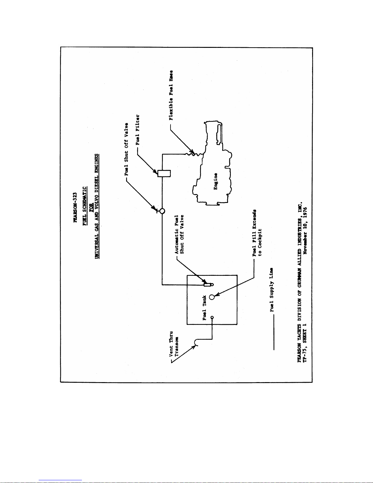
The fuel tank ventilates through a copper tube that extends from the
rear top of the tank to a small clamshell vent in the transom. The
fuel supply line is a copper tube that runs from the tank through the
electric and manual shut off valves to the filter and emerges from
the filter as a flexible hose connecting with the engine fuel pump.
When leaving the boat for an extended period, when cleaning the fuel
filter, or when making repairs or adjustments, it is recommended that
the fuel valve be shut off.
With the diesel engine installation, in addition to the fuel filter
installed in the fuel supply line, there is an additional filter
integral with the engine.
(DIAGRAM OF FUEL SYSTEM FOLLOWS)
Pearson 323 Owners Manual (1978 model year) Page 20 of 38
Page 21
Pearson 323 Owners Manual (1978 model year) Page 21 of 38
Page 22

PEARSON YACHTS
OWNER'S GUIDE AND PROTECTION PLAN
PEARSON-323
SECTION X: ENGINE COOLING SYSTEM
Please refer to your engine operating manual found among the ship's
papers, for a complete description of the cooling system. The engine
cooling water intake and valve are located in the bilge on the port
side of the keel between the two cabin sole hatches. The in line
strainer (diesel only, not gas) is located in the bilge just aft of
the intake and valve with access through the aft cabin sole hatch.
Cooling water flows through the cooling circuit of the engine and is
then discharged into the exhaust elbow located under the galley sink
with access through the locker door on the galley face. Water and
exhaust is then led aft through the rubber exhaust hose to the
transom outlet. There is a scoop strainer facing aft on the outside
of the hull (port side) that insures adequate water flow. The in line
strainer on the diesel installation should be cleaned frequently - it
collects material and hence reduces the water flow to the engine. It
is located in the bilge with access through the aft cabin hatch.
Always close the raw water intake before servicing the strainer.
NOTE: It is recommended that the intake valve be closed when the boat
is to be left unattended for an extended period.
Pearson 323 Owners Manual (1978 model year) Page 22 of 38
Page 23

PEARSON YACHTS
OWNER'S GUIDE AND PROTECTION PLAN
SECTION XI. A: STANDARD FRESH WATER SYSTEM
There are two (2) standard 19 gallon water tanks located port and
starboard under the main cabin berths. Total standard capacity 38
gallons.
In addition an optional 40 gallon water tank is offered which is
located forward under the V-berth.
As standard a foot pump is supplied at the galley sink and a hand
pump at the vanity sink.
With the optional hot and cold pressure system the vanity hand pump
is deleted. Access to the tank connections is through traps under the
berth cushions.
FILLING TANKS
Tank fills are located on deck (marked water) located as follows: A.
Port and starboard tanks outboard near main mast. B Optional forward
tank on fore deck.
A clear plastic inspection plate is located on the top of each tank,
making it possible to determine the amount of water in the tank and
to facilitate cleaning.
CAUTION: Do not overfill tanks. Filling above the level of the tank
tops will subject the tanks to excessive hydrostatic pressure
resulting in possible damage to the tanks.
Your boat is supplied with deck mounted fresh water fills. The tanks
are fitted with inspection plates. Excessive pressure can be placed
on the tanks by leaving water in the fill pipes. Use caution when
filling the water tanks. Do not fill above the tank. Be sure to check
the water level at the inspection plate in order to preclude
overfilling.
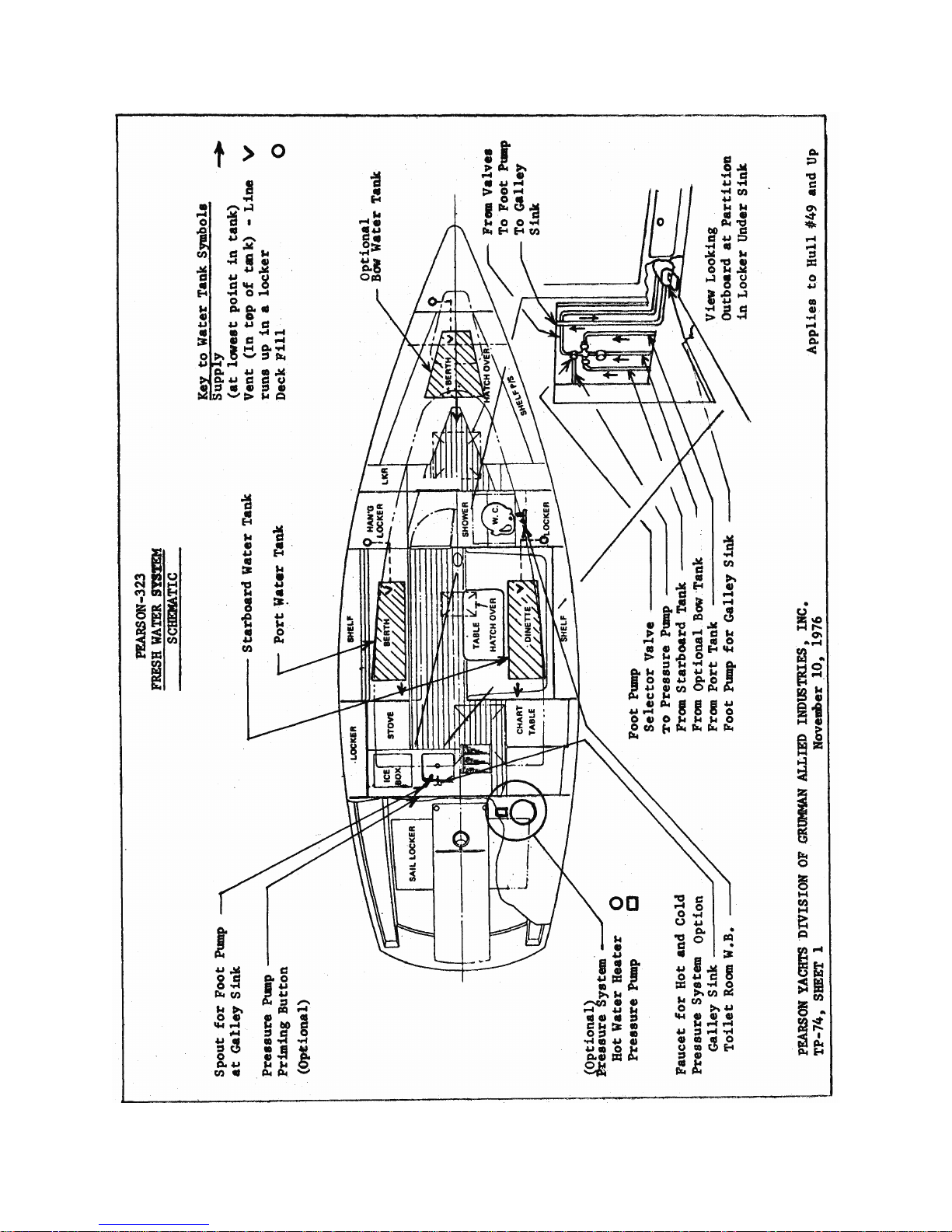
Tank Selection: Each tank has its own selector valve located under
the galley sink (see diagram). Only one valve should be open at a
time. To open the valve, turn it counter-clockwise until it stops,
then close it about 1/4 turn.
Tank Usage: For extended cruising, you will probably want to fill all
of your water tanks. To help maintain proper trim, we suggest water
be drawn from the tanks in the following sequence. 1. Optional bow
tank. 2. Port tank. 3. Starboard tank.
Optional Foot Pump Operation: Open the foot pump selector valve
located under galley sink (see diagram). Depress foot pump pedal
located on face of galley counter under stove for galley sink.
(Diagram of Fresh Water System Follows)
Pearson 323 Owners Manual (1978 model year) Page 23 of 38
Page 24

PEARSON YACHTS
OWNER'S GUIDE AND PROTECTION PLAN
SECTION XI. B: OPTIONAL HOT AND COLD PRESSURE WATER SYSTEM
Hot and cold pressure water is supplied to the galley sink, wash
basin, and shower.
Pressure System Operation:
Close foot pump selector valve. Turn pressure system switch on
distribution panel to ON position. Depress pressure pump priming
button located on galley bulkhead near sink. This will start pressure
pump. With button depressed, open one faucet until a steady stream of
water appears, then closed the faucet and repeat the procedure with
the other faucet. With both faucets closed, keep the button depressed
until pump stops automatically.
NOTE: If pump continues to run and a steady stream does not take
place, tank may be nearly empty. Select another tank and repeat
priming procedures.
Hot Water Heater:
This unit is located at the forward end of the starboard sail locker
(see separate literature for operation and maintenance).
Hot water is produced in two ways:
A. By running the main engine, part of its cooling water passes
through a coil in the heater thank, heating the water in the
tank.
B. If the boat is wired for dick side electricity, an electrical
heating element in the tank will heat the water.
Pressure Pump:
This pump is located at the forward end of the starboard sail locker.
(See separate literature for operation and maintenance).
Pearson 323 Owners Manual (1978 model year) Page 24 of 38
Page 25
Pearson 323 Owners Manual (1978 model year) Page 25 of 38
Page 26

PEARSON YACHTS
OWNER'S GUIDE AND PROTECTION PLAN
PEARSON-323
SECTION XII: BILGE SYSTEM
The low point of the bilge is located aft of the ballast keel. Access to this
area is through the aft cabin sole hatch next to the stove.
Bilge suction hose with strainer is located in the bilge sump area. The bilge
pump is located in the port aft end of the cockpit. Bilge pump discharge is in
the transom, port side with the standard gas engine and starboard side with the
optional diesel engine.
Periodically lift the suction hose and clear the strainer of any foreign
material.
Pearson 323 Owners Manual (1978 model year) Page 26 of 38
Page 27

PEARSON YACHTS
OWNER'S GUIDE AND PROTECTION PLAN
PEARSON-323
SECTION XIII: ELECTRICAL SYSTEM
To provide electrical power to the various circuits, turn on the master switch
located on the aft bulkhead under the main companionway. Place the switch in
position 1, 2, or ALL. In position 1 or 2, electrical power will be drawn from
battery 1 or 2, and with the engine running, battery 1 or 2 will be charged by
the engine alternator. In position ALL, both batteries will provide power and
will be charged simultaneously.
NOTE: Do not change position of battery switch while engine is running. To do
so may burn out the diodes on the alternator.
A good procedure to follow is to charge both batteries (ALL position) while
running under power; then when the engine is shut down, turn to position 1 or 2.
As a simple reminder, use the date, even days, position 2; odd days, position 1.
With the master switch on, turning the toggle switches on the adjacent
distribution panel to the ON position will energize the various circuits such as
cabin lights, instruments, etc. When leaving the boat for extended periods of
time, turn off the master switch and the toggle switches on the distribution
panel.
Pearson 323 Owners Manual (1978 model year) Page 27 of 38
Page 28
Pearson 323 Owners Manual (1978 model year) Page 28 of 38
Page 29
Pearson 323 Owners Manual (1978 model year) Page 29 of 38
Page 30
Pearson 323 Owners Manual (1978 model year) Page 30 of 38
Page 31

PEARSON YACHTS
OWNER'S GUIDE AND PROTECTION PLAN
PEARSON-323
SECTION XIV: WATER CLOSET, SINK, COCKPIT AND DECK SCUPPERS
Intake seacock is located to starboard under the outboard portion of the forward
dinette seat. Discharge seacock is located to starboard under the aft portion of
the V-berth. To reach the valves, lift the appropriate seat cushions and access
traps.
NOTE: Seacocks are open when valve handles are in line with hose coming from
valve.
The seacocks should be greased periodically to insure free operation and water
tightness.
Close both valves when leaving the boat for any period of time.
Galley Sink Drain:
The sink discharges into the port cockpit scupper.
Cockpit Scuppers:
Both scuppers are fitted with seacocks which are located in the engine room on
each side of the engine. Access to these valves is through the removable engine
access panel behind the companionway ladder.
Deck Scuppers:
There are two deck scuppers; port and starboard that discharge at the boot top.
Pearson 323 Owners Manual (1978 model year) Page 31 of 38
Page 32

Pearson 323 Owners Manual (1978 model year) Page 32 of 38
PEARSON YACHTS
OWNER'S GUIDE AND PROTECTION PLAN
PEARSON-323
SECTION XV: SUMP PUMP
The vanity wash basin and the pan for the optional shower both drain directly
into a sump box which is drained by an electric pump. To turn the sump on, place
pressure system switch on distribution panel to ON position. A second switch
located near the wash basin controls the pump operation.
When draining the wash basin, turn the switch on until all water has been pumped
overboard.
When using the shower, turn the pump on and let it run until you have finished
showering.
The sump pump is located under the cabin sole near the main mast and discharges
through a gate valve located in the forward cabin, on the starboard side, under
the aft portion of the V-berth.
Page 33

PEARSON YACHTS
OWNER'S GUIDE AND PROTECTION PLAN
PEARSON-323
SECTION XVI: ALCOHOL STOVE
Please refer to manufacturer's literature before operating. All stoves are
alcohol fueled for your safety.
(WATER WILL EXTINGUISH AN ALCOHOL FIRE.)
The alcohol tank is located against the aft bulkhead on the starboard side
between the chart table seat and the galley. The tank is located away from the
stove as a safety precaution. Should you experience a dangerous flare-up, shut
off the alcohol supply quickly by turning the valve on top of the tank. We
suggest that when the stove is not in use, you release the pressure in the
alcohol tank. While this is somewhat inconvenient, it will extend the useful
life of the burner tips.
Pearson 323 Owners Manual (1978 model year) Page 33 of 38
Page 34

PEARSON YACHTS
OWNER'S GUIDE AND PROTECTION PLAN
PEARSON-323
SECTION XVII: OPTIONAL EQUIPMENT
1. FATHOMETER: Please refer to manufacturer literature provided.
2. SPEEDOMETER: Please refer to manufacturer's literature provided.
3. APPARENT WIND INDICATOR: Please refer to manufacturer's
literature provided.
4. MASTHEAD & SPREADER LIGHTS: On/Off switches on switch panel.
5. ELECTRICAL REFRIGERATION: Refer to manufacturer's literature for
complete operational details.
6. PROPANE (LPG.) STOVE: Please refer to manufacturer's literature
before operating. Never use flame to check for leaks.
CAUTION
A. Keep container valve closed when boat is unattended. Close it
immediately in any emergency.
B. Be sure all appliance valves are closed before opening container
valve.
C. Always apply lit match or other flame to burner before opening
burner valve.
D. Close master valve at appliance whenever appliance is not in
use.
E. Test system for leakage at least twice a month and after any
emergency in accordance with the following procedures.
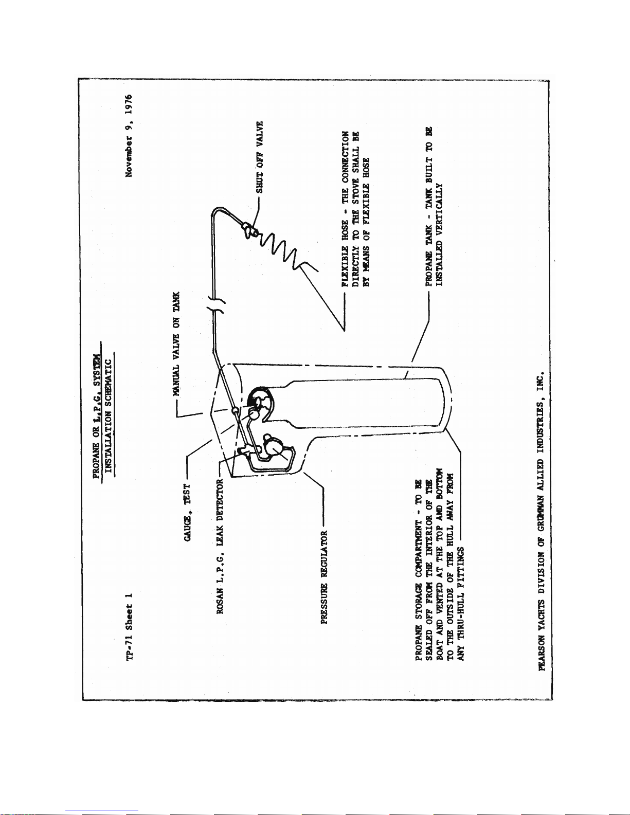
Procedure 1: With appliance valves closed, the master shutoff valve
on the appliance open, and with container valve open, note pressure
on the gauge. Close container valve. If the pressure drops, locate
leakage by application of liquid detergent or soapy water solution at
all connections.
Procedure 2: As shown in diagram a leak detector is provided in the
line at the container compartment. See Manufacturer's instructions.
To locate leak proceed as indicated above.
(DIAGRAM OF PROPANE SYSTEM FOLLOWS) 7. SHORE POWER CONVERTER: Refer
to manufacturer's literature.
Pearson 323 Owners Manual (1978 model year) Page 34 of 38
Page 35

CAUTION: With the shore power connected turn the battery switch on
before any electrical equipment.
Optional Shore Power:
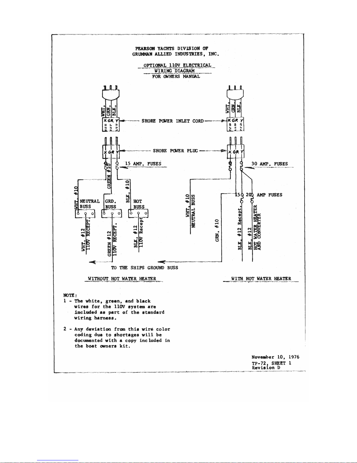
Two 110 volt AC outlets are provided one in the galley, the other in
the toilet room.
The shore power receptacle is located in the cockpit. (POWER CORD TO
BE PROVIDED BY OWNER.)
The shore power circuit utilizes the normal AC. three-wire system.
The circuit is protected by two 30-amp fuses located on the
electrical control center on the main engine room bulkhead,
accessible through port sail locker.
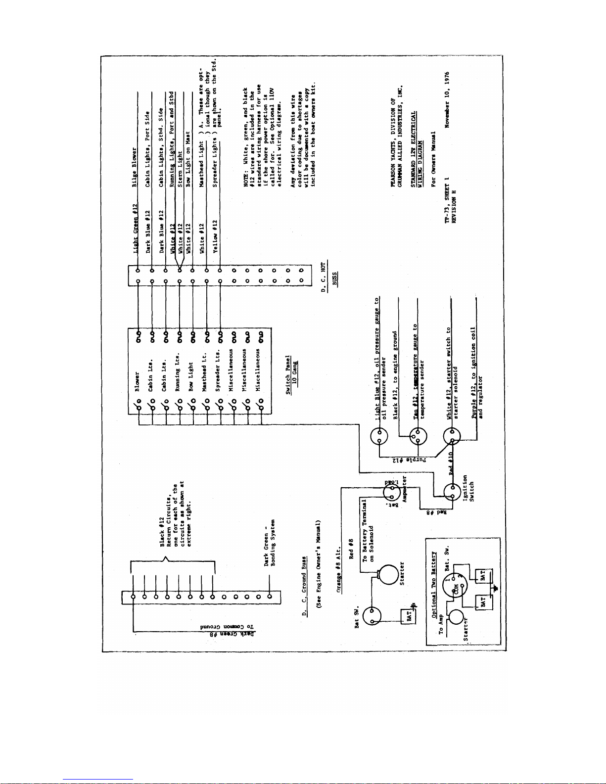
(DIAGRAMS OF STANDARD AND OPTIONAL ELECTRICAL SYSTEMS FOLLOWS)
Pearson 323 Owners Manual (1978 model year) Page 35 of 38
Page 36
Pearson 323 Owners Manual (1978 model year) Page 36 of 38
Page 37

Pearson 323 Owners Manual (1978 model year) Page 37 of 38
PEARSON YACHTS
OWNER'S GUIDE AND PROTECTION PLAN
PEARSON-323
SECTION XVIII: FIRE EXTINGUISHERS
Fire extinguishers are to be provided by the owner. Fire on board a boat is a
very real and serious hazard. Fire extinguishers of the size and type
recommended by the United States Coast Guard should be installed immediately.
Even more important than the number of extinguishers is the location of the
units. They should be located near the areas where fire are most likely to occur
(engine and tank and galley). The extinguishers should be readily accessible in
an emergency and not cut off from reach by the fire itself.
As a general guide we recommend locating fire extinguishers in the following
areas:
1 in forward cabin
1 near galley
1 in cockpit locker accessible from outside the cabin.
COAST GUARD REGULATIONS
CONSULT YOUR LOCAL COAST GUARD AND COAST GUARD AUXILIARY FOR THE REQUIRED SAFETY
EQUIPMENT AND PERTINENT SAFE BOATING REGULATIONS.
Page 38

Pearson 323 Owners Manual (1978 model year) Page 38 of 38
PEARSON YACHTS
OWNER'S GUIDE AND PROTECTION PLAN
SECTION XIX: CARE & MAINTENANCE
Regular preventive maintenance is required to keep any boat in "as new"
condition. It starts with the day after delivery and continues throughout the
year. The heaviest time commitment is, of course, in the spring but one should
always be observant of the condition of such areas as running rigging, finishes,
the engine, head,, and other moving parts of gear and tackle. The following
comments are intended to serve as an initial guideline. You will no doubt want
to develop a check list of your own.
FIBERGLASS SURFACES
The glossy outer surface of your laminated fiberglass boat is known as
"gelcoat", a polyester resin into which coloring pigments have been
incorporated. It should be hosed with fresh water after every outing and
routinely washed with a good detergent. Use a sponge on the smooth surfaces,
while a stiff deck brush will be helpful on the non-skid surfaces, followed by
more fresh water to avoid streaking the topsides. Do not use abrasive cleaners,
as they will rapidly dull the gelcoat surface.
At least once a year the smooth gelcoat surfaces should be waxed and polished
with a good automotive wax or boat wax that is especially formulated for
fiberglass surfaces. A power buffer will make work on the large areas, like the
hull, easier, but care must be taken not to cut through the gelcoat surface,
particularly at corners and edges. Color in gelcoat, as in any material exposed
to direct sunlight, tends to fade, dull,, or chalk, and will require heavier
buffing to bring back the original luster. For power cleaning, use a LIGHT
abrasive cleaner, while a heavier rubbing compound may be used when polishing by
hand. After buffing, wax and polish all surfaces EXCEPT THE NON-SKID AREAS.
Regardless of the amount of care lavished on your boat occasional scratches,
cracks, small gouges, along with a badly crushed section or even a large hole,
are bound to appear. It is best to discuss the proper course of action with your
local dealer or a professional who is SKILLED IN THE REPAIR OF FIBERGLASS
SAILBOATS.
We have included a copy of Fiberglass Boat Care and Repair Manual by
Owens-Corning Fiberglas Corporation that gives some very good basic information
for your perusal. Minor gelcoat touch-up and patching is not difficult. It takes
a little study, practice, and, if possible, help from a knowledgeable person.
WOODWORK
The exterior and interior trim is teak, one of the most durable and decorative
of all hardwoods - but it must be maintained to keep it from splitting and
discoloring.
To help teak maintain its natural color and life longer, treat it regularly with
a preparation such as Boatlife's "Teak Brite" or Woolsey's "Teak Dressing".
CAUTION: Never use steel wool instead of bronze wool or sandpaper. Small
filaments of steel break off and cause rust spots that are very difficult to
remove.
CUSHION CARE
The fabric used on all Pearson yachts has been treated with Scotchgard for your
protection. When cleaning is required, we recommend that a mild detergent be
used. Lather up the cushion with a damp sponge. Rinse with fresh water.
CAUTION: Do not remove covers from foam.
 Loading...