

Pearl Iron Jet IRONJ 05, Iron Jet IRONJH 05, Iron Jet IRONJ 10, Iron Jet IRONJ 07, Iron Jet IRONJ 15 Installation And Operating Instructions Manual
...Page 1
INSTALLATION AND OPERATING INSTRUCTIONS
TO AVOID SERIOUS OR FATAL PERSONAL INJURY OR MAJOR
PROPERTY DAMAGE, READ AND FOLLOW ALL SAFETY
INSTRUCTIONS IN MANUAL AND ON PUMP.
This is a SAFETY ALERT SYMBOL. When
you see this symbol on the pump or in the
manual, look for one of the following signal
words and be alert to the potential for
personal injury or property damage.
Warns of hazards that WILL cause serious
personal injury, death or major property
!
damage.
DANGER
Warns of hazards that CAN cause serious
personal injury, death or major property
!
damage.
WARNING
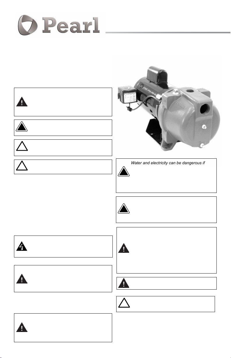
IRONJET
shallow well jet pumps
Warns of hazards that CAN cause personal
!
injury or property damage.
CAUTION
NOTICE: PLEASE READ AND UNDERSTAND THIS MANUAL
BEFORE OPERATE OR INSTALL THE PRODUCT. IF YOU HAVE
ANY QUESTION, PLEASE CONTACT YOUR DISTRIBUTOR FOR
INSTRUCTION.
THIS MANUAL MUST BE KEPT WITH THE PUMP.
MAINTAIN ALL SAFETY LABELS.
IMPORTANT PRE-INSTALLATION INFORMATION
Hazardous voltage can shock, burn or cause
death. All electrical work must be performed
by a qualied technician. Always follow the
local applicable electrical code.
The pump must be connected to a dedicated
electrical circuit protected by a properly sized
circuit breaker or fuses. Install a disconnect
Control Panel where required by the local
code.
Code questions should be directed to your electrical inspector.
See Chart 1 for specific information.
Always disconnect the power source before
installing or servicing the pump. This motors
come with an automatic thermal overload
protection, this feature may allow an
overheated pump to restart suddenly.
Water and electricity can be dangerous if
certain precautions are not adhered to. This
pump is designed to operate in a safe way in
!
a water environment; however, improper use
DANGER
and installation can result in personal harm
from electrical shock. Please pay attention to
the following warnings.
Never touch this pump, when it is touching
water, in water, or even in a moist
environment. Always unplug (disconnect the
!
electricity) when working on or installing
DANGER
the unit.
Do not use this pump with ammable or
explosive liquids such as oil, gasoline,
kerosene, ethanol, etc. Using this pump
with or near ammable liquids can cause an
explosion or re, resulting in property damage,
serious personal injury and/or death. Pumping
any of the above mentioned liquids voids the
warranty. Always make sure that this pump
is pumping liquid with same composition as
water.
Do not stand in water when the pump is
connected to the power supply.
This pump has been evaluated for use with
!
water only.
CAUTION
NOTICE: This pumps has been designed for working in presence
of water. Working without water will cause severe damage to
the pump.
Page 2
A qualied electrician must perform all the
!
wiring.
CAUTION
1. GENERAL INFORMATION
1.1. Read this Instruction Manual thoroughly prior to any work.
Work should be undertaken by qualified persons only.
ATTENTION!
Important information for installers of
this equipment!
This equipment is intended for installation by technically
qualified personnel. Failure to install it in compliance with
national and local electrical codes, and with motor suppliers
recommendations, may result in electrical shock or fire hazard,
unsatisfactory performance, and equipment failure. Installation
information is available from pump manufacturers and directly
from motor suppliers. Retain this information sheet with the
equipment for future reference.
WARNING
Serious or fatal electrical shock may result from failure to
connect the motor, control enclosures, metal plumbing, and all
other metal near the motor or cable, to the power supply ground
terminal using wire no smaller than motor cable wires. To reduce
risk of electrical shock, disconnect power before working on or
around the water system.
1. LOCATION
The pump should be installed in a dry, accessible place not
subject to freezing temperatures. If installed in a pump pit or
other location subject to dampness, proper ventilation must be
provided to avoid moisture damage to the electrical equipment.
2. PIPING
Galvanized steel or plastic pipe is recommended. If copper or
other dis-similar metal piping is used, a di-electric union or
bushing is recommended where the piping is connected to the
pump body. The pipe used should be cleaned and free of scale.
Ream ends of pipe to remove burrs. Check threads to see that
they are clean and not damaged. Horizontal runs of suction
pipe must slope upwards from the well to the pump to avoid air
pockets in the line which will make it difficult, if not impossible, to
prime the pump. The recommended slope is one inch in ten feet.
If pump must be offset an appreciable distance from the well,
the size of horizontal pipe should be increased to reduce
friction losses.
If using di-electric bushing, hand start bushing into female end of
pump housing (or other female connection) first. Use a six-sided
socket to tighten the bushing.
The bushing should be fully inserted into the female
connection. After the male end of the bushing is fully installed, hand
start pipe (or other male connection) into the female end of the
bushing. Failure to follow these guidelines may damage the bushing.
Caution should be taken to not cross-thread the bushing.
temporarily wasting the water outdoors or to drain. The pump
should be operated until the water runs clear, without sand, mud
or rust.
This procedure will eliminate the danger of pumping dirty water
into the pressure tank and home appliances. When water runs
clear, re-connect discharge line to tank and service.
4. WIRING (Use copper conductors only)
Be certain that wire and fuses of correct size are installed. Be
certain the phase, voltage, and cycles of the supply circuit are
the same as that shown on the motor name plate.
It is strongly recommended that a separate electric line, well
protected against fire, be run from electrical service to the pump,
with a fused switch box at the pump.
In the event of fire, this precaution will permit continuous
operation of your pumping system. For added safety, the pump
and motor should be properly grounded to the well casing or to a
separate ground rod driven eight feet into the ground.
NOTE: For proper fuse, circuit breaker and wire sizes in your
area, follow local codes. Otherwise:
Wire Gage and Standard Fuse Sizes
MOTOR
1/2 HP 12 12 20 amp 15 amp 20 amp 15 amp
3/4 HP 10 12 25 amp 15 amp 30 amp 15 amp
1 1/2 HP 6 10 35 amp 25 amp 40 amp 20 amp
* Time delay fuses and circuit breakers (Single Phase).
For distances of 100 feet and over from meter to motor, larger
wire than shown may be required.
WIRE SIZE *FUSETRON *CIRCUIT BRKR
SIZE
115 V 230 V 115 V 230 V 115 V 230 V
1 HP 8 12 30 amp 20 amp 35 amp 20 amp
5. MOTORS
Motors are equipped with sealed ball bearings and require little
attention.
If motor repeatedly stops, cools off, and starts again, the cause
or trouble must be located and corrected. Do not cover motor
with canvas or other material that may interfere with proper air
circulation and cause over-heating.
6. PRESSURE SWITCH
The pressure switch is set at the factory to start the pump at
30 PSI and stop it at 50 PSI. In the event a change is necessary,
remove the switch cover and adjust either the operating
pressure or differential between start and stop (if available) by
turning screws, marked on switch, in the direction required.
Wiring directions are given on the pressure switch may
damage the bushing. Caution should be taken to not
cross-thread the bushing.
3. FLUSHING
If the pump discharge line is connected to pressure tank or
house service, disconnect it and flush and clean the system by
Page 3

Well Seal
Submerge
5-10 Feet
Figure 1
Tee
We
ent
ll V
Foot Valve
& Strainer
Horizontal
Check Valve
We ll Point
Figure 2
Te e
rtical
Ve
Check Valve
A shallow well system should not be installed where total suction
lift exceeds 25 feet at sea level. Suction lift must be reduced at
the rate of approximately 1 foot per 1000 feet at elevation. Total
suction lift consists of the vertical distance from the water level
when pumping to the pump plus losses due to friction in the pipe
line. The volume of water delivered decreases with an increased
suction lift.
Drilled, bored or dug wells may employ an arrangement as in
Figure 1. Driven wells and sandpoints employ the configuration
in Figure 2.
1. a) Install a foot valve on the bottom of the suction line and
place it 5 to 10 feet below the draw down level, that is, the level
of the water when the unit is pumping its rated capacity. It should
be far enough from the bottom of the well to avoid pumping sand
and mud. (Figure 1)
b) On driven well installation, install a spring dog- check valve
on the vertical pipe at least five feet above the well point, or install a horizontal check valve in the suction line near the pump.
(Figure 2)
2. Check the foot valve, see that it seats properly and that no
obstruction prevents its opening or closing. A leaky foot valve
may cause excessive cycling (motor starts and stops).
3. Lower first length of suction pipe, with attached foot valve
into the well, fill pipe with clean water. If water recedes a leak is
indicated. If no leaks occurs, assemble the remaining section(s)
of pipe and check again for leaks.
4. Install the well seal at the top of the well casing and tighten
well seal bolts. (Figure 1)
5. Install a tee at top of suction pipe, with a plug in the top
opening, and connect through a union to the female thread in
the pump body.
6. Connect pump discharge to pressure tank, and pressure tank
to house plumbing.
7. After piping is completed and motor is properly wired,
remove the priming plug on top of pump and fill pump with clean
water. Allow time for air in the system to escape, and refill pump if
necessary before replacing the priming plug. Start motor and the
unit should operate. If it does not, it may be necessary to reprime.
8. When unit has built up to maximum pressure, and has
automatically stopped, check all piping both suction and
discharge lines for leaks, as they will be under pressure.
NOTE: If the unit is to be used with a vacuum type air volume
control where the source of supply is on a level with the pump
or above it (artesian well, pond, cistern or shallow well with less
than five feet lift) a valve should be installed in the suction line
that may be partially closed to cause the pump to operate under
a moderate suction lift of 8-10 ft. to insure correct operation of
the air volume control which is operated by vacuum.
7. PERFORMANCE DATA
IRONJ 05
HP
0.5
IRONJH 05
HP
0.5
IRONJ 07
HP
0.75
IRONJ 10
HP
1.0
IRONJ 15
HP
1.5
Suction
Lift Depth
(feet)
5 20 13 8 3 58
10 17 12 7 2 56
15 15 10 6 1.5 52
20 13 9.4 5 51
25 11 8 3 51
Suction
Lift Depth
(feet)
5 12 9 6 3.5 83
10 11 8 5 3.3 80
15 10 7 4.8 2.8 77
20 8 6.5 4.5 2.5 74
25 6.3 6 4.2 2.2 72
Suction
Lift Depth
(feet)
5 22.2 21 16 11 6.5 69
10 22 19 15 9 5.5 67
15 21.5 18 14 8 3.5 65
20 21 15 13 7 2 62
25 20 11 10 6 1.8 60
Suction
Lift Depth
(feet)
5 25 22 16 8 70
10 23 19 14 6.5 69
15 20 18.5 13 4 66
20 18 17 12 2.5 63
25 16 15 10 2 60
Suction
Lift Depth
(feet)
5 29 26 22 16 87
10 25 24 20 15 82
15 21 22 19 13 80
20 19 20 18 11 75
25 16 15 15 9 74
Discharge Pressure - PSI
20 30 40 50 60
Flow US GPM
Discharge Pressure - PSI
20 30 40 50 60
Flow US GPM
Discharge Pressure - PSI
20 30 40 50 60
Flow US GPM
Discharge Pressure - PSI
20 30 40 50 60
Flow US GPM
Discharge Pressure - PSI
20 30 40 50 60
Flow US GPM
Max
Shut-OFF
PSI
Max
Shut-OFF
PSI
Max
Shut-OFF
PSI
Max
Shut-OFF
PSI
Max
Shut-OFF
PSI
Page 4

8. VOLTAGE CHANGE PROCEDURE
8.1 VOLTAGE CHANGE PROCEDURE FOR IRONJ 05 - IRONJH 05 - IRONJ 07
1
Unscrew and
remove the cover.
2
Check the voltage
set from factory.
8.2 VOLTAGE CHANGE PROCEDURE FOR IRONJ 10 - IRONJ 15
1
Unscrew and
remove the cover.
2
Remove the
Voltage plug.
3
If you want to
power the pump
with 115 V,
rotate the plug
to 115 V.
4
If you want to
power the pump
with 230 V,
rotate the plug
to 230 V.
3
Install the Voltage
Plug aligning the
arrow with the
voltage needed.
4
Choose connection
for 230 V.
5
Close the cover.
5
Choose connection
for 115 V.
6
Reinstall the cover
back.
9. PEARL MOTOR DATA
MOTOR
PART #
IRON J-05 0.5 115V / 230V 1 1.90 10.8 / 5.4
IRON J-07 0.75 115V / 230V 1 1.90 14.2 / 7.1
IRON J-10 1 115V / 230V 1 1.75 16.6 / 8.3
IRON J-15 1.5 115V / 230V 1 1.60 21 / 10.5
PD WATER SYSTEMS - 3000 W. 16 Ave. Miami, FL 33012. TEL: (954) 474 9090 FAX: (954) 889 0413
HP VOLTS PHASE
www.pdwatersystems.com | pdwatersystems
SERVICE
FACTOR
Pump MAX.
LOAD AMPS
WATER SYSTEMS
10. PEARL MOTOS ARE PRE-WIRED BY HP:
- 1/2 wired for 115 Volt.
- 3/4 - 1 1/2 HP wired for 230 Volt.
 Loading...