

Page 1
PEARL DRUM PEDAL
P-2050C/P-2050B
To get optimum performance of your "P-2050C / P-2050B" Drum Pedal,
please read this Instruction Manual before playing.
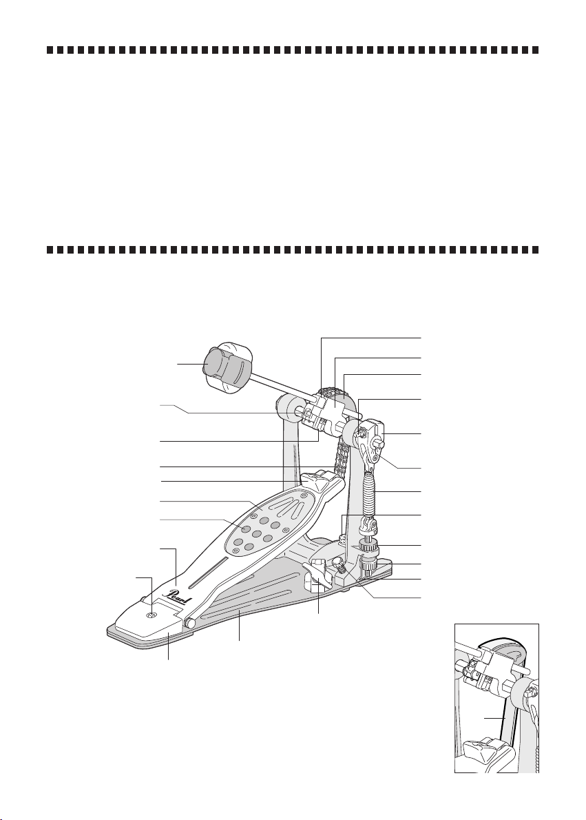
Control Core Quad Beater
Key Bolt
(for Footboard Angle
Adjustment )
Key Bolt
(for Beater Setting)
Dual Chain
Toe Stopper
Traction Plate
Traction Grip
Footboard
Key Bolt
(for PowerShifter)
P-2050C
Heel Plate
Instruction Manual
Congratulations on your purchase!
Beater Setting Stopper
Beater Holder Link
Interchangeable Cam
Key Bolt (for Beater
Angle Adjustment)
Uni-Lock Beater
Angle Cam
Gauge
Spring
Adjustment Knob
(for Hoop Clamp)
Upper Nut
Lower Nut
Click Lock
Anchor Screw
Wing Bolt
(for Hoop Clamp)
Power Plate
P-2050B
Belt
Page 2
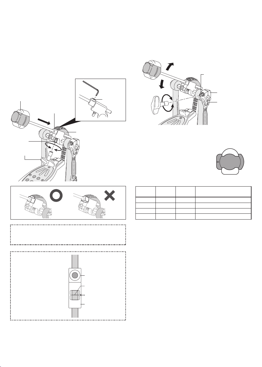
Beater Setting
Insert the Control Core Quad Beater into the Beater Holder
Link with the desired face toward the bass drum head until
it stops against the Beater Setting Stopper. Tighten the Key
Bolt with a Tuning Key to secure (Fig.1-A). Make sure that
the Beater Setting Stopper is flush against the Beater
Holder Link (Fig.1-B). To adjust the height of the Quad
Beater, loosen the Allen Screw on the Beater Setting
Stopper with the provided hexagonal wrench. Set the Quad
Beater to the desired height and re-tighten the Allen Screw
(Fig. 1-C).
Control Core Quad Beater
Beater Setting Stopper
Beater Holder Link
Key Bolt
Tuning Key
Fig.1-A
Allen screw
Fig.1-C
Fig.1-B
Beater Angle Adjustment
The beater angle can be adjusted by loosening the Key Bolt
on the Uni-Lock Beater Angle Cam. Adjust to desired
setting and tighten Key Bolt to secure. For small incremental changes or to index settings use the Gauge located on
the Uni-Lock Beater Angle Cam.
Key Bolt
Uni-Lock Beater
Angle Cam
Gauge
Fig.3
Control Core Quad Beater
The Control Core Quad Beater has
four striking surfaces, each capable
of producing a different sound.
Please refer to the following chart to
determine the sound best suited to
your playing style (Fig. 4).
Surface Sound
A Felt Vertical Warm Sound with Sharp Attack
B Felt Horizontal Warm Sound with Fat Attack
C Plastic Vertical Bright Sound with Sharp Attack
D Plastic Horizontal Bright Sound with Fat Attack
Surface
Material
Contact
Area
A
D C
B
Fig.4
Tip
The Beater Set ting Stopper pre serves the height setting if the
beater is removed when transporting the pedal.
Tip
In the initial factory setting,
the Index Mark on the
Beater Holder Link and
Marking on the Shaft is
aligned in the Window as
shown (Fig. 2).
Beater Setting Stopper
Marking on the shaft
Index Mark
Beater Holder Link
Fig.2
Page 3

Footboard Angle Adjustment
To adjust the footboard angle, remove beater and loosen
Key Bolt on the Drive Connector as shown (Fig.5). Slide the
Drive Connector of the Chain or Belt to one of three
positions, tighten the Key Bolt and replace beater.
Key Bolt
Drive Connector
Removable Toe-Stop
The Toe-Stop may be removed
for individual playing style. To
remove simply unscrew Key
Bolt and remove Toe-Stop
from footboard (Fig.8). Store in
secure location for possible
future use.
Key Bolt
Toe-Stop
Fig.8
Fig.5
Spring Tension Adjustment
The P-2050C / P-2050B Pedal features our patented Click
Lock spring tension retention system. To adjust the spring
tension, disable the Click Lock by lifting the lever upward
(Fig.6-B) and loosen the Upper Nut shown in (Fig. 6-A). To
increase spring tension, turn the Lower Nut clockwise. To
decrease spring tension turn the Lower Nut
counter-clockwise. Once desired spring tension is
achieved, tighten the Upper Nut against pedal frame firmly.
To secure the setting, lower the Click Lock lever to engage
the grooves around the Lower Nut until you feel the lever
"Click.” Before playing, make sure that both Upper and
Lower Nuts are tight and the Click Lock lever is in a vertical
position with both sides of the lever engaged in the grooves
around the Lower Nut (Fig.7).
Spring
Upper Nut
Lower Nut
Anchor Screw
Anchor Screw
To prevent the bass drum from
creeping forward while playing
turn the Anchor Screws
clockwise to extend the spikes
downward into the floor
(Fig.9).
Fig.9
CAUTION
Recommended for carpeted surfaces only. Use on hard flooring
may result in damage to the surface from spikes. Check to ensure
spikes are retracted when used on these surfaces.
Hoop Clamp system
To attach your pedal to the bass drum, slide the bass drum
hoop between the Hoop Clamp and the bottom lip of the
pedal. Square the pedal and tighten the Wing Bolt to
secure the pedal to the bass drum hoop. The Hoop Clamp
system is fully adjustable and comes preset from the
factory to accommodate a variety of hoop thicknesses. To
adjust, use the hexagonal wrench provided to loosen the
Allen Screw on the side of the Adjustment Knob. Rotate the
Adjustment Knob until proper fit is achieved then tighten the
Allen Screw to secure setting (Fig. 10).
Adjustment Knob
Click Lock
Fig.6-A
Fig.6-B
Fig.7
Wing Bolt
Hoop Clamp
Allen Screw
Fig.10
Note
If the heel of the pedal lifts while playing, loosen the Adjustment
Knob to cha nge the angle of the Hoop Clamp until the pedal
remains flat.
Page 4

Interchangeable Cam System
Our exclusive Cam System provides four interchangeable
color-coded cams (black, white, blue and red ) allowing
you to quickly change the power and feel of the pedal to
suit your individual playing style. From the factory, the Black
Cam is mounted to the P-2050C Chain Drive Pedal; the Red
Cam is mounted to P-2050B Belt Drive Pedal. To change
Cams, push the Release Button on the Wheel housing and
remove the Cam as shown (Fig.11). To attach the Cam, it is
not necessary to press the Release Button, simply snap the
Cam onto the Wheel as shown (Fig.12). Check to make
sure that the Cam is seated correctly and is secure to the
Wheel housing.
Traction Grip and Traction Plate Adjustment
The Traction Grip dots can be totally removed or inserted
as needed to custom tailor the amount of traction for your
personal playing style. To remove the Traction Grip dots,
loosen the Allen Screws holding the Traction Plate with the
provided hexagonal wrench and remove the Traction Plate
from the footboard (Fig.13). The Traction Plate is also
reversible to provide just the right amount of grip at either
the front or rear of the footboard (Fig.14).
Traction Plate
Release Button
Fig.11
Fig.12
Note
Do not force the Cam onto the Wheel. If needed adjust the position
of the Cam to fit properly.
Do not use the pedal without the Cam attached, damage may
occur.
Included 4 Optional 2
Black Blue PurpleRed
Black : Linear Action Cam
This is Pearl's original "perfect circle" Cam design. It offers super ior
power and a very natural, perfectly balanced action and smooth feel.
White : Oversized Linear Cam
The White Cam is a slightly over sized "perfect circle" Cam. It offers a
very natural, smooth action, with great power and balance, with a
slightly lighter pedal feel.
Blue : Progressive Cam
This is the very popular "off-center" axis type Cam design. It offers a
light feel in the beginning that accelerates with speed and power upon
impact.
Red : Radical Progressive Cam
The Red Cam features an extreme "off-center" axis design. The action
is similar to the Blue Cam but with a lighter feel at the beginning of the
stroke.
Purple : Aggressive Action Cam
The Purple Cam provides aggressive acceleration for huge power and
response, second only to the Red Cam. (CAM-PL)
Yellow : Inverse Action Cam
The Yellow Cam provides a slight inverse action. When maximum
power is required, this is the Cam of choice. (CAM-YL)
White
Yellow
Fig.14
Traction Grip dots
Fig.13
Note
When putting the Traction Plate back, finger-tighten the four screws
to prevent cross-threading; then tighten the screws securely.
Do not use the Pedal without the Traction Plate mounted. It could
cause injury to your foot.
PowerShifter
The PowerShifter function allows you to change the feel and
action of the pedal by shifting the footboard position back
and forth. To change the position, loosen the Key Bolt in the
heel of the footboard and move the footboard to the
desired position: A, B or C. Tighten the Key Bolt again
(Fig.15).
Key Bolt
A
B
C
A: Strong B: Normal C: Light
A
B
C
Fig.15
Note
Make sure that the heel is flush with the Power Plate to prevent
damage to the pedal.
Rubber Mats
To maximize traction of the rubber mats underneath the
Power Plate keep them clean and dust free using a damp
cotton towel.
Page 5

Optional Items (sold separately)
・ Belt Assembly (BCA-250) / Chain Assembly (CCA-5)
Both the Belt and Chain Assemblies are interchangeable
on all Eliminator pedals to provide easy conversion from
chain or belt drive.
・ Oil (OL-300)
The P-2050C / P-2050B Pedal features precision NiNjA
bearings for incredible speed and smoothness. To keep
them functioning at their maximum speed and
performance it's recommended that you apply genuine
NiNjA Oil at regular intervals (Fig.16).
Oil
Fig.16
CAUTION
Periodically check all Allen Screws for tightness and
tighten them with the provided hexagonal wrench as
needed.
Periodically apply lube to all moving parts such as the
Chain, Cam Roller, Footboard Hinge, etc. for optimal
speed and extended life of your pedal.
Only use NiNjA Oil on NiNjA bearings.
Products and specifications are subject to change without notice.
http: //www.pearldrum.com
Printed in China
-1601-
 Loading...