

Page 1

MARCHING SNARE DRUM STAND
MSS-3000
Congratulations on your purchase!
To get optimum performance of your MSS-3000 Marching Snare Drum Stand,
please read this Instruction Manual before playing.
Instruction Manual
Top Section
Base Section
Page 2
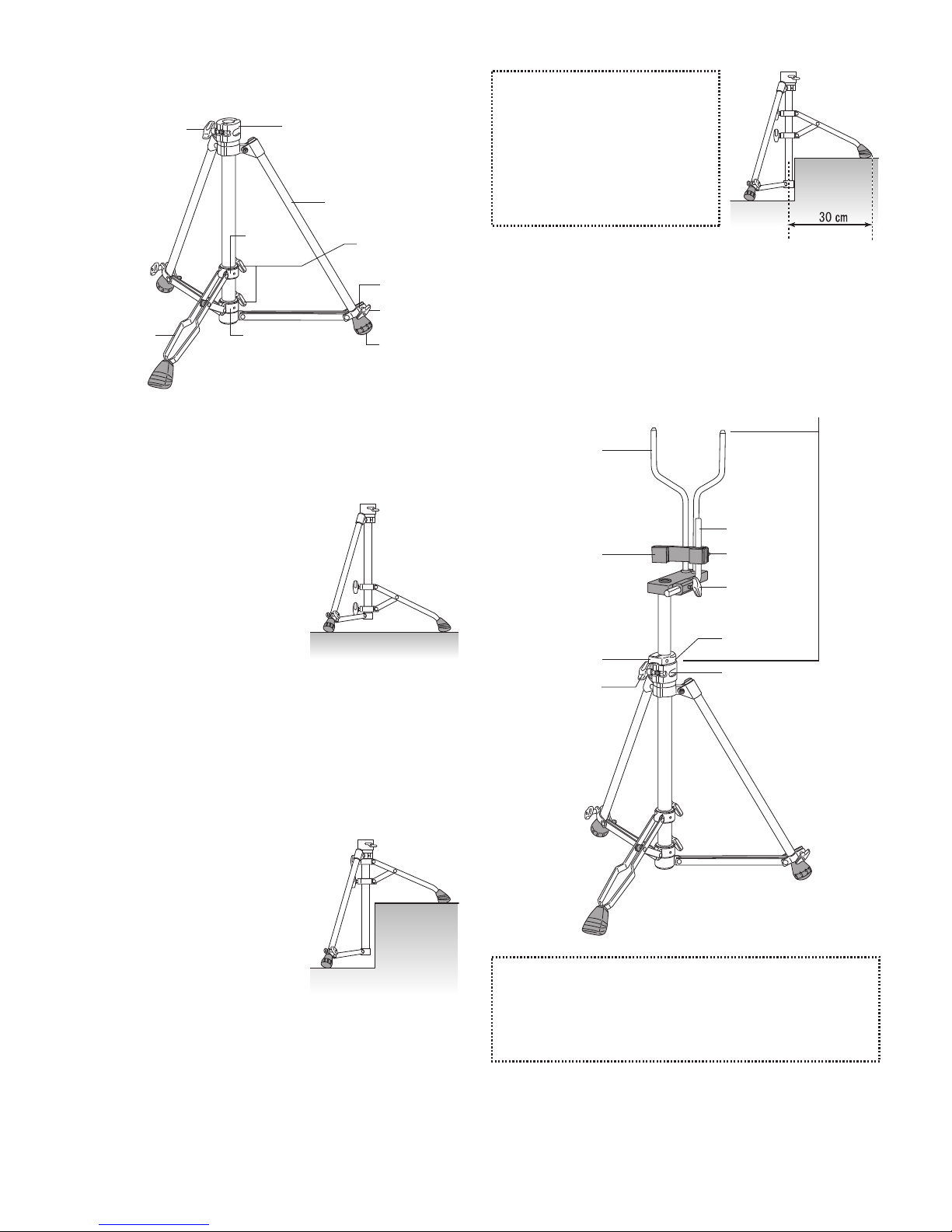
Fig.2
Fig.3
Fig.4
Fig.5
Die-Cast Joint
Movable Leg
Lower Bracket
Rubber Tip
Wing Nut
Wing Nut
Stable Leg
Stopper
Upper
Bracket
Wing Bolt
Base Section Assembly (Fig.1)
a) Using on Flat Surface (As shown in Fig. 2)
1. Loosen the Wing Nuts on the
Stoppers of the Stable Legs.
2. Slide the Stoppers to the end
of the Legs to the Rubber Tip,
and tighten the Wing Nuts.
3. Loosen the Wing Bolt on the
Upper Bracket of the Movable
Leg.
4. Slide the Upper Bracket up
and adjust the position until
the base stands straight up,
and tighten the Wing Bolt.
Top Section Assembly (Fig.5)
1. Loosen the Wing Nut of the Die-Cast Joint of the Base.
2. Insert the top section as shown, and tighten the Wing Nut
and the Key Bolt on the Stop Lock.
b) Using on Uneven Surface (As shown in Fig. 3)
1. Loosen the Wing Nuts on the
Stoppers of the Stable Legs.
2. Slide the Stoppers to the end
of the Legs to the Rubber Tip,
and tighten the Wing Nuts.
3. Loosen the Wing Bolts on the
Upper and Lower Bracket of
the Movable Leg.
4. Slide the Upper Bracket to the
top of the pipe, and tighten the
Wing Bolt.
5. Slide the Lower Bracket and
adjust the position until the
base stands straight up, and
tighten the Wing Bolt.
Fig.1
Note
If the distance between the Rubber
Tip of the Movable Leg and the
center of the pipe becomes shorter
than 30 cm, slide both the Upper
and Lower Bracket and adjust their
positions. Make sure to adjust the
position so that the base stands
straight up. (Fig. 4)
Note
・For height adjustment, loosen the Wing Bolt on the Die-Cast Joint
and the Key Bolt on the Stop Lock, and slide the Top Section.
Tighten the Wing Bolt on the Die-Cast Joint and the Key Bolt on
the Stop Lock when desired height is achieved. Do NOT make
height adjustment with the Snare Drum mounted on the stand.
Top Section
Die-Cast Joint
Wing Nut
Key Bolt
Wing Bolt
Key Bolt
Stability Arm
Stop Lock
Support Bumper
Snare Arm
Page 3

Wing Bolt
Setting the Snare Drum
1. Adjust the position of the
Stability Arm so that the
Support Bumper is just
in front of the Snare
Arms as shown. (Fig.6)
2. Spread the Snare Arms and attach the Snare Drum
facing the direction shown in Fig. 7-B.
3. Loosen the Key Bolt on the Support Bumper and adjust
its position up or down so that it is touching the bottom
hoop of the snare drum. (Fig.7-A, 7-B)
4. Press the Support Bumper
against the bottom hoop and
tighten the Wing Bolt . (Fig.8)
Note
・This stand is designed to be used with snare drums with CXSA-1
or MXSA-1 attachment. Snare drums other than these could result
in unstable settings and should not be used.
・Do not overtighten the Key Bolt on the Support Bumper. The
Support Bumper will deform and would become stuck on the
Stability Arm.
・Do not use on unstable or sloped surfaces, as it could
cause the stand to fall, resulting in damage and/or
injury.
・Do not make adjustments on the Base Section with the
Top Section inserted.
・Do not move the stand with the Snare Drum mounted
on the stand.
・Before use, check all Stop Locks to assure they are
properly positioned and secured.
・Do not mount the Snare Drum without the Support
Bumper. The Snare Drum could become unstable and
could cause damage and/or injury.
・Periodically check all Wing Nuts, Wing Bolts and the
nuts under the Snare Arm to assure they are tightened
securely.
・When making adjustments, support and control the
parts being adjusted to prevent them from falling or
pinching fingers that may be in the way.
・When folding the legs, be careful not to pinch your
fingers between the leg and the stand.
・When handling tubular hardware, do not put your
fingers into the tubes top prevent injury to your fingers.
CAUTION
http://www.pearldrum.com
Products and specifications are subject to change without notice.
Printed in China
-1406-
Stability
Arm
Support
Bumper
Snare Arm
Key Bolt
Support
Bumper
Support
Bumper
Bottom
Hoop
Support
Bumper
Fig.7-A
Fig.6
Fig.8
Fig.7-B
 Loading...