

Page 1
INSTALLATION AND OPERATING INSTRUCTIONS
1. GENERAL INFORMATION
Before using the product carefully read the information
contained in this instruction manual, the manual should be kept
for future reference.
Italian is the original language of this instruction manual, this
language is the reference language in case of discrepancies in
the translations.
This manual is part of the essential safety requirement and must
be retained until the product is finally decommissioned.
The customer, in case of loss, can request a copy of the manual
by contacting the manufacturer or their agent, specifying the
type of product data shown on the label of the machine (see 2.3
Marking)
Any changes, alterations or modifications made to the product or
part of it, not authorized by the manufacturer, will revoke the “CE
declaration” and warranty.
This appliance should not be operated by children younger
than 8 years, people with reduced physical, sensory or mental
capacities, or inexperienced people who are not familiar with the
product, unless they are given close supervision or instructions
on how to use it safely and are made aware by a responsible
person of the dangers its use might entail.
Children must not play with the appliance. It is the user’s
responsibility to clean and maintain the appliance.
Children should never clean or maintain it unless they are given
supervision.
Do not use in ponds, tanks or swimming pools or where people
may enter or come into contact with the water.
Read carefully the installation section which sets forth:
- The maximum permissible structural working pressure
(chapter 3.1).
- The type and section of the power cable (chapter 6.5).
- The type of electrical protection to be installed (chapter 6.5).
1.1. SYMBOLS
To improve the understanding of the manual, below are
indicated the symbols used with the related meaning.
Information and warnings that must be observed,
otherwise there is a risk that the machine could damage or compromise personnel safety.
The failure to observe electrical information and
warnings, could damage the machine or compromise
personnel safety.
Information and warnings that must be observed,
otherwise there is a risk that compromise personnel
safety.
Notes and warnings for the correct management of the
machine and its parts.
i
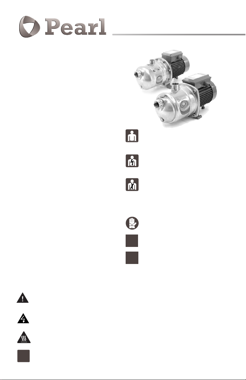
MXA-MSC
Horizontal multistage pumps
Operations that could be performed by the final user.
After carefully reading of the instructions, is responsible
for maintenance under normal conditions. They are
authorized to affect standard maintenance operations.
Operations that must be performed by a qualified electrician. Specialized technician authorised to affect all
electrical operations including maintenance. They are
able to operate with in the presence of high voltages.
Operations that must be done performed by a qualified
technician. Specialized technician able to install the
device, under normal conditions, working during “maintenance”, and allowed to do electrical and mechanical
interventions for maintenance. They must be capable of
executing simple electrical and mechanical operations
related to the maintenance of the device.
Indicates that it is mandatory to use individual protection devices.
Operations that must be done with the device
switched off and disconnected from the power
OFF
supply.
Operations that must be done with the device
ON
switched on.
1.2. MANUFACTURER NAME AND ADDRESS
PD Water Systems
3000 W. 16 Ave. Miami, FL 33012
Tel: (954) 4749090 | Fax: (954) 8890413
info@pdwatersystems.com | www.pdwatersystems.com
1.3. AUTHORIZED OPERATORS
The product is intended for use by expert operators divided into
end users and specialized technicians.
(see the symbols above).
It’s forbidden, for the end user, carry out operations which must
be done only by specialized technicians. The manufacturer
declines any liability for damage related to the non-compliance
of this warning.Provide enough clearance around the unit for
motor ventilation and for filling and draining the pump.
Page 2
1.4. WARRANTY
For the product warranty refer to the general terms and
conditions of sale.
The warranty covers only the replacement and the repair
of the defective parts of the goods (recognized by the
i
manufacturer).
The Warranty will not be considered in the following cases:
- Whenever the use of the device does not conform to the
instructions and information described in this manual.
- In case of changes or variations made without authorization of
the manufacturer.
- In case of technical interventions executed by a nonauthorized
personnel.
- In case of failing to carry out adequate maintenance.
1.5. TECHNICAL ASSISTANCE
Any further information about the documentation, technical
assistance and spare parts, shall be requested to the:
manufacturer (paragraph 1.2).
2. TECHNICAL DESCRIPTION
Horizontal Multi-Stage Close Coupled Pumps.
MSC: version in AISI 304 with impeller PPO-GF.
MXA: version in AISI 304 with impeller PPO-GF.
2.1. INTENDED USE
For clean liquids: non-explosive and non-flammable, nonhazardous for health or the environment, nonaggressive for pump
materials, not containing abrasives, solid or fibrous particles.
For MXH with seal rings in EPDM the pump is not suitable for
use with oil.
Liquid temperature:
- MSC, MCC from 32 °F to + 122 °F.
- MXA from 32 °F to + 95 °F.
2.2. IMPROPER USE
The device is designed and built only for the purpose described
in paragraph 2.1.
Improper use of the device is forbidden, as is use under
conditions other than those indicated in these
instructions.
Improper use of the product reduces the safety and the efficiency
of the device, the manufacturer shall not be responsible for
failure or accident due to improper use.
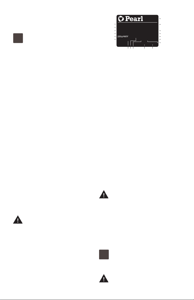
2.3. MARKING
The following picture is a copy of the name-plate that is on the
external case of the pump.
18
XXXXXXX
Q min/max X/X US gpm
H max/min X/X ft TEFC
X kW (XHp) S.F.
V3~60HzP F X
X/X AT amb XX F CONT l.cl. X X lb
81 01 1
1 Pump type
97
2 Delivery
3 Head
4 Rated power
5 Tension nominale
6 Nom. motor current
7 Ambient temperature
8 Fréquence
9 Operation Duty
XXXXXXX
n XXXX/min
Tmax liq.XX F SF
10 Liquid temperature
11 Service factor
12 Insulation class
13 Weight
14 Power factor
15 Rotation speed rpm
16 Protection
17 Serial number
17
16
15
14
13
XX
12
18 Certifications
3. TECHNICAL FEATURES
3.1. TECHNICAL DATA
Dimensions and weight (see technical catalogue).
Nominal speed 3450 rpm
Protection TEFC
The electric data marked on the label are referred to
the nominal power of the motor.
Sound pressure: < 70 dB (A).
Max. starts per hour: 15 at regular intervals.
Maximum permissible pressure in the pump casing:
262 ft (116 PSI).
3.2. OPERATING CONDITIONS
Installation in well ventilated location protected from
the weather, with a maximum ambient temperature of
104 °F.
4. SAFETY
4.1. GENERAL PROVISIONS
Before using the product it is necessary to know all the
safety indications.
Carefully read all operating instructions and the indications defined for the different steps: from transportation to disposal.
The specialized technicians must carefully comply with all applicable standards and laws, including local regulations of the
country where the pump is sold.
The device has been built in conformity with the current safety
laws. The improper use could damage people, animals and objects.
The manufacturer declines any liability in the event of damage
due to improper use or use under conditions other than those
indicated on the name-plate and in these instructions.
Follow the routine maintenance schedules and the
promptly replace damaged parts, this will allows the
i
device to work in the best conditions.
Use only original spare parts provided by the manufacturer or
from an authorized distributor.
Don’t remove or change the labels placed on the device.
Do not start the device in case of defects or damaged
parts.
Page 3
Maintenance operations, requiring full or partial
disassembly of the device, must be done only after
disconnection from the supply.
4.2. SAFETY DEVICES
The device has an external case that prevents any contact with
internal parts.
4.3. RESIDUAL RISKS
The appliance, designed for use, when used in-line with the
design and safety rules, doesn’t have residual risks.
4.4. INFORMATION AND SAFETY SIGNALS
For this kind of product there will not be any signals on the
product.
4.5. INDIVIDUAL PROTECTION DEVICES
During installation, starting and maintenance it is suggested
to the authorized operators to consider the use of individual
protection devices suitable for described activities.
During ordinary and extraordinary maintenance interventions,
safety gloves are required.
Signal individual protection device HAND PROTECTION
(gloves for protection against chemical, thermal and
mechanical risks).
5. TRANSPORTATION AND HANDLING
The product is packed to maintain the content intact.
During transportation avoid to stack excessive weights.
Ensure that during the transportation the box cannot move.
It is not necessary to use any special vehicle to transport the
packaged device.
The transport vehicles must comply, for the weight and
dimensions, with the chosen product (see technical catalogue
dimensions and weights).
5.1. HANDLING
Handle with care, the packages must not receive impacts.
Avoid to impact onto the package materials that could damage
the pump.
If the weight exceeds 55 lbs the package must be handled by two
person at the same time.
6. INSTALLATION
6.1. DIMENSIONS
For the dimensions of the device (see technical catalog).
6.2. AMBIENT REQUIREMENTS AND INSTALLATION SITE DIMENSIONS
The customer has to prepare the installation site in order to
guarantee the right installation and in order to fulfill the device
requirements (electrical supply, etc.).
The place where the device will be installed must fulfill the
requirements in the paragraph 3.2.
It’s absolutely forbidden to install the machine in an environment
with potentially explosive atmosphere.
6.3. UNPACKING
Inspect the device in order to check any damages which
i
may have occurred during transportation.
Package material, once removed, must be discarded/recycled
according to local laws of the destination country.
6.4. INSTALLATION
See installation examples, par. 13 fig. 1 and 2.
The pumps must be installed with the rotor axis in the horizontal
position and with the feet under the pump. Place the pump as
close as possible to the suction source.
Provide space around the pump for motor ventilation, to allow
for checking of shaft rota-tion, for filling and draining the pump
and to allow for collection of the liquid to be removed (especially
for draining liquids which are harmful or have to be removed at
temperatures higher than 140 °F).
6.4.1. PIPES
Ensure the insides of pipes are clean and unobstructed before
connection.
ATTENTION: The pipes connected to the pump should be
secured to rest clamps so that they do not transmit stress, strain or
vibrations to the pump (par. 13 fig. 3).
Tighten the pipes or union coupling to the extent sufficient to
ensure a tight seal.
Excessive torque may cause damage to the pump.
When the pipe or union coupling is mounted, keep the pump
casing connection blocked with a second wrench, making sure
the connection is not deformed by excessive tightening.
The pipe diameters must not be smaller than the pump
connections.
6.4.2. SUCTION PIPE
If the suction pipe is longer than 33 ft, use an internal pipe
diameter larger than the pump suction connection.
The suction pipe must be perfectly airtight and be led upwards in
order to avoid air pockets.
With a pump located above the water level (suction lift operation,
par. 13. fig. 2) fit a foot valve with strainer which must always
remain immersed.
If operating with flexible hoses use a reinforced spiral suction
hose, in order to avoid the hose narrowing due to suction vacuum.
With the liquid level on the suction side above the pump (inflow
under positive suction head, par. 13. fig.1) fit an inlet gate valve.
For suction from a storage tank fit an anti-backflow valve. Follow
local specifications if increasing network pressure.
Install a strainer on the suction side of the pump to prevent
foreign particles from entering the pump.
6.4.3. DELIVERY PIPE
Fit a gate valve in the delivery pipe to adjust delivery and head.
Install a pressure gauge.
With a geodetic head at outlet over 49 ft fit a check valve between the pump and the gate valve in order to protect the pump
from water hammering.
6.5. ELECTRICAL CONNECTION
OFF
Electrical connection must be carried out only by a qual-
ified electrician in accordance with local regulations.
Page 4

Always follow the National Electrical Code (NEC), or the
Canadian Electrical Code, as well as all local, state and provincial
codes. Code questions should be directed to your local electrical
inspector. Failure to follow electrical codes and OSHA safety
standards may result in personal injury or equipment damage.
Failure to follow manufacturer’s installation instructions may
result in electrical shock, fire hazard, personal injury or death,
damaged equipment, provide unsatisfactory performance, and
may void manufacturer’s warranty.
Install, ground and wire according to local and National
Electrical Code Requirements.
Electrical supply MUST match pump’s nameplate specifications.
Incorrect voltage can cause fire, damage to the motor and voids
the warranty.
Pumps not protected MUST be provided with contactors and
thermal overloads for single phase motors. See motor nameplate.
Use only copper wire to motor and ground. The ground wire
MUST be at least as large as the wire to the motor.
Wires should be color coded for ease of maintenance.
Compare the frequency and mains voltage with the name-plate
data and connect the supply conductors to the terminals in accordance with the appropriate diagram inside the terminal box
cover.
ATTENTION: Never allow washers or other metal parts to
fall into the internal cable opening between the terminal
box and stator. If this occurs, dismantle the motor to recover the object which has fallen inside.
If the terminal box is provided with an inlet gland, use a flexible
power supply cord of the H07 RN-F type with section of cable not
less than 11 TAB IEC 60335-1.
If the terminal box is provided with an inlet bushing, connect the
power supply cord through a conduit.
For use in swimming pools (not when persons are in the pool),
garden ponds and similar places, a residual current device with
IΔN not exceeding 30 mA must be installed in the supply circuit.
Install a device for disconnection from the mains (switch) with a
contact separation of at least 0,12 inch in all poles.
With a three-phase motor install an overload protection device
with curve D appropriate for the rated current of the pump.
Single-phase, are supplied with a capacitor connected to the terminals with an incorporated thermal protector.
ATTENTION: When the pump is fed by a frequency converter, the
minimum frequency should not fall below 25Hz and in any case
the total head of the pump should never be lower than 10 ft.
7. STARTUP AND OPERATION
7.1. Preliminary checks before start-up of the pump
Do not start-up the device in case of damaged parts.
7.2. FIRST STARTING
OFF
ATTENTION: never run the pump dry. Start the pump after filling
it completely with liquid.
When the pump is located above the water level (suction lift operation par. 13 fig. 2) or with a positive suction head which is too
low (less than 33 ft) to open the non-return valve, fill the pump
through the priming hole (par. 13 fig. 4).
When the liquid level on the suction side is above the pump (inflow under positive suction head par. 13 fig. 1), fill the pump by
opening the suction gate valve slowly and completely, keeping
the delivery gate valve open to release the air.
Before starting, check that the shaft turns by hand. For
this purpose use the screwdriver notch on the shaft end on the
ventilation side.
When starting, with a three-phase motor, check that the direction
of rotation is as shown by the arrows on the lantern bracket.
Otherwise, disconnect electrical power and reverse the
connections of two phases.
Check that the pump works within its field of perfor-mance
and that the absorbed current shown on the name-plate is not
exceeded. Otherwise adjust the delivery gate valve or the setting
of any pressure switches.
If a priming loss occurs (interruption of delivery flow) or if a
pressure oscillation is indicated by the pressure gauge, make
sure all the suction pipe couplings are perfectly sealed and
tighten the two sealed plugs on the pump casing.
Never run the pump for more than five minutes with a
closed gate valve.
Prolonged operation without a change of water in the pump
causes dangerous increases of temperature and pressure.
When the water is overheated due to prolonged operation with a
closed port, stop the pump before opening the gate valve.
To avoid any risk of danger to users and the creation of harmful
thermal stress in the pump and system due to large temperature
differentials, wait until the water has cooled inside the pump before starting again.
If the water is overheated on account of prolonged operation with
a non-primed or insufficiently filled pump (suction lift operation),
wait until cool before opening the draining and filling plugs.
Care must be taken when the pumped fluid has a high
temperature. Do not touch the fluid when its tempera-
ture is higher than 140 °F. Do not touch the pump when
the surface temperature is higher than 176 °F.
7.3. SELF-PRIMING (ONLY FOR MXA)
(Capability to clear the air in the suction pipe when starting with
the pump located above the water level).
Conditions for self-priming:
• suction pipe with connections perfectly airtight and properly
immersed in the water to be lifted;
• discharge pipe with a straight vertical free line above discharge
port, before a non-return valve.
• pump casing completely filled with clean cold water berfore
starting.
The pump is not self-priming with liquids containing oil, alcohol
or foaming substances.
The check valve prevents reverse siphoning through the pump
when the pump is stopped and retains water in the pump for
the next start.
Without a foot valve or a check valve on the suction connection
the filling operation must be repeated before each start-up.
ATTENTION: avoid a prolonged operation with unprimed
pump, without water delivery from the completely
opened outlet.
If the pump does not prime in 5 minutes: stop the motor,
remove the priming plug and add more water.
If necessary, repeat the priming operation after the pump has
been first emptied and then completely filled with clean cold
water.
7.4. SWITCH OFF OF THE PUMP
ON
Page 5

The appliance must be switch off every time there are faults.
(see troubleshooting).
The product is designed for a continuous duty, the switch off
is performed by disconnecting the power supply by means the
expected disconnecting devices. (see paragraph “6.5 Electrical
connection”).
8. MAINTENANCE
Before any operations it’s necessary to disconnect the power
supply.
If required ask to an electrician or to an expert technician.
Every maintenance operations, cleaning or reparation
executed with the electrical system under voltage, it
could cause serious injuries to people.
In case of extraordinary maintenance, or maintenance
operations that require part-removing, the operator must be a
qualified technician able to read schemes and drawings.
It is suggest to register all maintenance operation executed.
During maintenance keep particular attention in order to
avoid the introduction of small external parts, that could
i
compromise the device safety.
It is forbidden to execute any operations with the direct
use of hands. Use water-resistant, anti-cut gloves to
disassemble and clean the filter or in other particular
cases.
During maintenance operations external personnel is
i
not allowed.
Maintenance operations that are not described in this manual
must be made only by special personnel authorized by the
manufacturer.
For further technical information regarding the use or the
maintenance of the device, contact the manufacturer.
8.1. ROUTINE MAINTENANCE
ON
Before every maintenance operations disconnect the
power supply and make sure that the device could not
accidentally operate.
For good measure, as in the case of temporary
operation with dirty liquids, run the pump briefly with
clean water to remove deposits.
When the pump remains inactive it must be emptied completely
if there is a risk of freezing (par. 13 fig. 5).
Before restarting the unit, check that the shaft is not jammed and
fill the pump casing completely with liquid.
8.2. DISMANTLING THE SYSTEM
Close the suction and delivery gate valves and drain the pump
casing before dismantling the pump.
8.3. DISMANTLING THE PUMP
casing before dismantling the pump (par. 13 fig. 5).
For dismantling and re-assembly see construction in the cross
section drawing.
9. DISPOSAL
OFF
The final disposal of the device must be done by specialized
company.
Make sure the specialized company follows the classification of
the material parts for the separation.
Observe the local regulations and dispose the device accordingly
with the international rules for environment protection.
10. SPARE PARTS
10.1. Spare-parts request
When ordering spare parts, please quote their
designation, position number in the cross section
drawing and rated data from the pump name plate
(type, date and serial number).
The spare parts request shall be sent to the
manufacturer by phone, fax, e-mail.
11. PARTS
Nr. Designation
14.00 Pump casing
14.04 Plug (filling)
14.06 O-ring
14.12 Plug (draining)
14.16 O-ring
14.20 O-ring
14.24 Screw
14.28 Square nut
14.54 Wear ring (1)
16.00 Suction casing
16.14 Plunger
16.15 Spring
16.16 O-ring
16.17 Valve
20.00 Delivery casing
22.12 O-ring
22.16 O-ring
25.01 First stage casing
25.02 Stage casing
25.05 Last stage casing
25.10 Washer for missing
impeller
25.11 First stage spacer
28.00 Impeller
28.04 Impeller nut
28.08 Washer
32.00 Lantern bracket
34.00 Casing cover
34.12 Screw
36.00 Mechanical seal
36.51 Retaining ring, split
36.52 Shoulder ring
46.00 Deflector
64.13 Spacer sleeve
64.14 Spacer sleeve
64.15 Spacer sleeve
70.00 Lantern bracket
70.18 Screw
70.20 Screw
73.00 Pump-side bearing
76.00 Motor casing with winding
76.04 Cable gland
76.16 Support
76.20 Pin
76.54 Terminal box, set
78.00 Shaft with rotor packet
81.00 Fan-side bearing
82.00 Motor end shield, fan side
82.04 Compensating spring
82.08 Screw
88.00 Motor fan
88.04 Compensating spring
90.00 Fan cover
90.04 Screw
92.00 Tie-bolt
94.00 Capacitor
94.02 Capacitor gland
98.00 Terminal box cover
98.04 Screw
98.08 Gasket
OFF
Close the suction and delivery gate valves and drainthe pump
Page 6

PROBLEM POSSIBLE CAUSE SOLUTION
Check that the mains frequency and voltage correspond to the
electrical characteristics shown on the indicator plate.
Connect the power supply cable to the terminal board correctly.
Check that the thermal overload protection is set correctly (see
data on the engine indicator plate) and make sure that the
fuseboard upline of the engine has been properly connected.
Check the power supply and make sure that the pump shaft is
turning freely. Check that the thermal overload protection has
been set correctly (see engine indicator plate).
Replace the fuses, check the electric power supply and points.
Check that the mains frequency and voltage correspond to the
electrical characteristics shown on the indicator plate.
Check the power supply and make sure that the pump shaft is
turning freely. Check that the thermal overload protection has
been set correctly (see engine indicator plate).
Remove the cause of blockage as indicated in the “Blocked
pump” instruction booklet.
Repair or replace the engine by applying to an authorized
service center.
Rotation may be started directly from the pump shaft or from
thejoint (remember to turn off the electricity supply first ) or
contact an authorised service centre.
If possible, dismantle the pump casing and remove any
solid foreign bodies inside the rotor, if necessary contact an
authorized service center.
If the bearings are damaged replace them or if necessary
contact an authorized service center.
Check which part is not tight and seal the connection
adequately.
Clean or replace the bottom valve and use a suction pipe
suitable for the application.
Clean the filter, if necessary, replace it . Rotation may be started
directly from the pump shaft or from the joint (remember to
turn off the electricity supply first) or contact an authorised
service centre.
Use pipes and accessories suitable for the specific application.
Clean the rotor and install a suction filter to prevent other
foreign bodies from entering.
Replace the rotor, if necessary, contact an authorized service
center.
The pump is unsuitable.
Invert the electrical connections on the terminal board or
control panel.
Try to close the feeder gate partially and/or reduce the
difference in level of the pump and the liquid being aspirated.
Bring the pump closer to the suction tank so as to use a shorter
pipe. If necessary use a pipe of a wider diameter.
The motor does not start
Pump blocked
The pump functions but
no water comes out
Insufficient flow
Unsuitable power supply
Incorrect electrical connections
Engine overload protective device cuts in.
Blown or defective fuses
Shaft blocked
If the above causes have already been checked,
the engine may be malfunctioning
Prolonged periods of inactivity with
formation of rust inside the pump
Presence of solid bodies in the pump
rotor
Bearings siezed
Possible infiltration of air from suction tube
connections, drain plugs or filling of pump or from
the gaskets of the suction pipe
Foot valve blocked or suction pipe not fully
immersed in liquid
Suction filter blocked
Pipes and accessories with diameter too small
causing excessive loss of head
Presence of deposits or solid bodies in
the internal passages of the rotor
Rotor deteriorated
Worn rotor and pump case Replace the rotor and the pump casing.
Excessive viscosity of the liquid
pumped (if other than water)
Incorrect direction of rotation
Suction head excessive in relation to
the suction capacity of pump
Suction pipe too long
Page 7

PROBLEM POSSIBLE CAUSE SOLUTION
Rotating part unbalanced Check that no solid bodies are obstructing the rotor.
Worn bearings Replace the bearings.
Pump and pipes not firmly attached Anchor the delivery and suction piping as needed.
Noise and vibrations from
the pump
Leakage from the
mechanical seal
Flow too strong for the diameter of the
delivery pipe
Functioning in cavitation
Unbalanced power supply Check that the mains voltage is right
Incorrect alignment of pump-motor unit If necessary, the unit must be re-aligned
The mechanical seal has functioned
when dry or has stuck.
Mechanical seal scored by presence
of abrasive parts in the liquid pumped.
Mechanical seal unsuitable for the
type of application.
Slight initial drip during filling or on first
start-up.
Use bigger diameters or reduce the pump flow.
Reduce the flow by adjusting the feeder gate and/or using pipes
with a bigger internal diameter. Try to close the feeder gate
partially and/or reduce the difference in level of the pump and
the liquid being aspirated.
Replace the seal, if necessary contact an authorized service
center.
Make sure that the pump casing (and the suction pipe if the
pump is not self-priming) are full of liquid and that all the air
has been expelled.
Replace the seal, if necessary contact an authorized service
center.
Reduce the flow by adjusting the feeder gate and/or using pipes
with a bigger internal diameter.
Install a suction filter and use a seal suited to the
characteristics of the liquid being pumped.
Replace the seal, if necessary contact an authorized service
center.
Choose a seal with characteristics suitable for the specific
application
Wait for the seal to adjust to the rotation of the shaft. If the
problem persists.
Make sure that the pump casing (and the suction pipe if the
pump is not self-priming) are full of liquid and that all the air
has been expelled.
Install a suction filter and use a seal suited to the
characteristics of the liquid being pumped.
Choose a seal with characteristics suitable for the specific
application.
Or contact an authorized service center.
PD WATER SYSTEMS - 3000 W. 16 Ave. Miami, FL 33012. TEL: (954) 474 9090 FAX: (954) 889 0413
www.pdwatersystems.com | pdwatersystems
 Loading...