

Page 1
4MWP
4” Submersible Motors
INSTALLATION AND OPERATING INSTRUCTIONS
Page 2

4MWP
4” Submersible Motors
OVERVIEW
1.
Please read this documentation carefully before installation.
This manual gives important information concerning the installation, use and maintenance of the motors.
The contents of this manual refer to the standard product, as presented in the sales documentation.
The installation and operation must comply with the safety regulations in the country in which the product
is installed.
The entire operation must be carried out in a workmanlike manner.
Failure to comply with the safety regulations not only causes risk to personal safety, it can also damage
the equipment and it will invalidate every right to assistance under guarantee.
2. SAFTEY
Below are the warning symbols used in this manual to warn of perticular dangers
ELECTRIC SHOCK DANGER
The non observance of the prescription involves electric shock risk.
DANGER
The non observance of the prescription involves the risk of damages to persons
and / or equipment.
MECHNICAL DANGER
The non observance of the prescription involves the risk of technical damages
to the motor and / or installation.
3. APPLICATIONS
All the motors in the 4MWP ranges can be used to drive
submersible pumps in the conditions established in
CSA Standard C22.2 No. 100-14 (Motors and Generators)
UL Standard 1004-1 (Electric Motors),
and at the supply voltage / frequency specified on the rating plate.
The shaft extension and flange size of these motors comply with NEMA MG1:2016.
The power of the pumps coupled to these motors must be less than or equal to that of the motors.
Page 3

4” Submersible Motors
4. LIQUIDS IN WHICH THE MOTOR CAN OPERATE
This motor can be used in cold water.
Do not use this motor with corrosive or explosive liquids
Do not use this motor with particularly dirty or hard water
(impurities may deposit on the outer casing.
5. COMPATIBLE PUMPS
Make sure the motor is compatible with the pump. Incompatible combinations may cause problems.
In particular, before coupling the motor to the pump check that:
- The power of the motor is greater than or equal to the power absorbed by the pump end.
4MWP
- The rpm of the pump matches the rotational frequencey of the motor.
- The pump has a NEMA motor connection and that the shaft turns freely.
6. MOTOR POWERED BY A FREQUENCY CONVERTER
Variable Frequencey Drive’s VFD’s are used to change the rotational speed of the motor so that the out-put of the
attached pump adjusts to the users demand for water.
VFD’s also reduce the starting current and “water hammer” during starting.
PEARL’s three-phase, encapsulated submersible motors can be used with variable frequency drives (VFD) when
used within the guidelines listed here.
All three-phase, encapsulated submersible motors must have the VFD sized based on the motor’s nameplate maximum amps, NOT horsepower. The continuous rated amps of the VFD must be equal to or greater than the motor’s
nameplate maximum amps or warranty will be void.
The VFD must have one RLC output filter to limit the voltage peaks and/or to reduce the dV/dt of the pulses generated by the inverter. The application of the filter will help to reduce the stress on the motor insulation (thermal and
electrical). The filter can be installed at the inverter output to reduce the dV/dt value or at the motor terminals to
attenuate the voltage peaks amplitude.
The motor must reach or pass the 30 Hz operating speed within 1 second of the motor being energized.
If this does not occur, the motor bearings will be damaged and the motor life reduced.
Page 4

4MWP
4” Submersible Motors
6. VFD continued.
PD WATER SYSTEMS suggests these MAX values for three phase encapsulated submersible motors
Max. Vpeak voltage: 1000 V phase-phase
Max. dV/dt :2000 V/μs
Filters are usually applied when the power cable to the motor is longer than 50ft (15.2m)
PD WATER SYSTEMS suggests the use of an input filter when the VFD is used in a residential area, to protect other
devices connected to the same mains from noise caused by the VFD
Frequency range: 30 Hz – 60 Hz
Drive carrier frequency: The range must be from 4.5k to 5k Hz .
Higher values will increase the quantity of Voltage Spikes x per second and reduce motor insulation lifetime.
Lower values give a poor shape to the power curve.
Ramp-up time / Ramp down time: | df/dt | > 30 Hz/sec (where f indicates the frequency) to ensure the life of the
thrust bearings
The motor’s operating speed must always operate so the minimum cooling flows are reached.
0.50 ft/sec for 6-inch motors
0.98 ft/sec for 4-inch motors
Motor overload protection must trip within a time equal to or faster than how indicated by Class 10 overload curve
and must trip within 115% of the nameplate Max. Amp.
PEARL’s encapsulated submersible motors are not declared inverter duty motors by NEMA MG1
standards. The reason is NEMA MG1 standard part 31 does not include a section covering
encapsulated winding designs.
PEARL’s submersible motors can be used with VFDs without problems or warranty concerns providing
all PD WATER SYSTEMS guidelines are followed.
PEARL’s single-phase, 2- and 3-wire, encapsulated submersible motors hould only be used with the
appropriate variable speed drive.
7. INSTALLATION
Before installing the motor, read both the motor and pump instructions manuals.
Keep both manuals an a safe place.
If the product shows any signs of damage, do not proceed with installation and call your local
stockest / distributor.
You must use suitable equipment and protective devices. Observe all accident prevention regulations.
Installations must always e in accordance with current local and/or national regulations, legislation and bylaws
governing installation of water and power equipment.
PEARL submersible motors are designed to be used in a shaft up vertical position.
During acceleration, the pump thrust increases as its output head increases. In cases where the pump head stays
below its normal operating range during startup and full speed condition, the pump may create upward thrust. This
creates upward thrust on the motor upthrust bearing. This is an acceptable operation for short periods at each start,
but running continuously with upthrust will cause excessive wear on the upthrust bearing.
Page 5

4MWP
4” Submersible Motors
8. ELECTRICAL CONNECTIONS TO THE ELECTRIC PUMP
Electrical connections may only be performed by a qualified installer in compliance with current
regulations.
Make sure that the supply voltage and frequency are compatible with the electrical panel.
The relative information is shown on the motor rating plate and in the documents supplied with the panel.
Provide suitable short circuit protection on the supply line.
Before proceeding, make sure that all the connections (even if they are potential-free) are voltage-free.
Unless otherwise specified in local bylaws, the supply line must be fitted with:
- a short circuit protection device,
- a high sensitivity ground-fault circuit interrupter (GFCI) residual current circuit breaker (30mA)
for additional protection from electrocution in case of inefficient grounding,
- a general switch with a contact aperture of at least 3 millimetres.
Ground the system in compliance with current regulations
Table 1: Power supply voltage tolerances
Power supply voltage tolerances:-
Frequencey in Hz Phase ~ Voltage Tolerance %
60 1 115v -10% +6 %
60 1 230v -10% +6 %
60 3 480v -10% +6 %
60 3 575v -10% +6 %
Single-phase version
Connect the electric pump to a supply line via a suitable electrical control panel containing the
overload protection and the capacitor.
Refer to the wiring diagram on the outer casing of the motor and in figure 1 and the documentation supplied with
the electrical panel.
Refer to the motor rating plate for the capacity of the capacitor.
Install the electrical panel in a sheltered area.
Three-phase version
Connect the electric pump to a supply line via a suitable electrical control panel .
Install the electrical panel in a sheltered area.
Refer to the documentation supplied with the electrical panel.
For connections to any external control devices (e.g.: pressure switch, float) follow the instructions supplied with
these devices
9. MAINTENANCE, SERVICE
Before proceeding, always make sure the motor is disconnected from the supply line.
Maintenance operations may only be performed by expert and qualified people.
Use suitable equipment and protective devices. Observe all accident prevention regulations.
Do not attempt to disconnect the connector from the motor head cable.
This may only be done by authorised personnel.
The motor does not require any scheduled routine maintenance.
Users wishing to prepare a maintenance schedule should bear in mind that maintenance frequencies depend on the
conditions of use.
For any requirements, please contact our Sales and Service Department.
Page 6

4MWP
4” Submersible Motors
10. SPARE PARTS
Only use original spare parts to replace faulty components.
Always specify the exact type of motor and code when requesting our Sales and Assistance Service for technical
information or spare parts.
Only use origional spare parts to replace faulty components. Unsuitable spare parts may cause the product to work
incorrectly and cause hazards for people and property.
11. STORAGE
PEARL submersible motors are a water-lubricated design.
The fill solution consists of a mixture of deionized water and Propylene Glycol (a non-toxic antifreeze).
The solution will prevent damage from freezing in temperatures to -23°F (-5°C);
motors should be stored in areas that do not go below this temperature.
There may be an interchange of fill solution with well water during operation. Care must be taken with motors
removed from wells during freezing conditions to prevent damage.
When the storage temperature does not exceed 104°F (40°C), storage time should be limited to two years. Where
temperatures reach 100° to 130°F, storage time should be limited to one year.
Loss of a few drops of liquid will not damage the motor as an excess amount is provided, and the filter check valve
will allow lost liquid to be replaced by filtered well water upon installation. If there is reason to believe there has
been a considerable amount of leakage, consult the factory for checking procedures.
PEARL recommend that you leave the motor in its original packaging until the day of installation.
When standing the motor upright make sure that it cannot fall over (shaft always upwards).
Do not subject the motor to direct sunlight or other heat sources.
12. FREQUENCY OF STARTS
The average number of starts per day over a period of months or years influences the life of a
submersible pumping system.
Excessive cycling affects the life of control components such as pressure switches, starters, relays and capacitors.
Rapid cycling can also cause motor spline damage, bearing damage, and motor
overheating.
All these conditions can lead to reduced motor life.
The pump size, tank size and other controls should be selected to keep the starts per day as low as practical for
longest life.
4 Inch motors should run a minimum of two minutes in order to dissipate heat built up from starting.
Table2: Maximum # starts per day
Motor Rating
Maximum # starts per day
HP KW SINGLE-PHASE THREE-PHASE
0.5 - 1.0 0.37 - 0.75 300 300
1.5 - 5.0 1.1 - 3.7 100 300
7.5 - 10 5.5 - 7.5 50 200
Page 7

4MWP
4” Submersible Motors
13. MOUNTING POSITION
PEARL submersible motors are designed primarily for operation in the vertical, shaft-up position.
During acceleration, the pump thrust increases as its output head increases. In cases where the pump head stays
below its normal operating range during startup and full speed condition, the pump may create upward thrust. This
creates upward thrust on the motor upthrust bearing. This is an acceptable operation for short periods at each start,
but running continuously with upthrust may cause excessive wear on the upthrust bearing
With certain restrictions, motors are also suitable for operations in positions from shaft-up to shaft-horizontal. As
the mounting position becomes further from vertical and closer to horizontal, the probability of shortened thrust
bearing life increases. For normal thrust bearing life expectancy with motor positions other than shaft-up, follow
these recommendations:
1. All the motors in the range can be installed horizontally as long as the axial thrust of the
pump never falls below 100 N while it is working.
2. Do not use in systems which can run even for short periods at full speed without thrust
toward the motor
3. Minimize the frequency of starts, Six inch motors should have a minimum of 20 minutes
between starts or starting attempts
Page 8
4” Submersible Motors
14. WATER TEMPERATURE AND FLOW
PEARL standard submersible motors are designed to operate up to maximum service factor
horsepower in water up to 95°F (35°C).
A minimum flow of 0.98 ft/sec for 4” motors is required for proper cooling.
Table 3: Minimum GPM required for motor cooling in water up to 95°F (35°C)
Minimum GPM required for motor cooling in water up to 95°F (35°C)
4MWP
Casing or Sleeve
I.D. Inches (mm)
4" 102 6.5 (24.5)
5" 127 28 (106)
6" 152 55 (208)
7" 178 86 (325)
8" 203 122 (461)
10" 254 209 (791)
12" 305 315 (1192)
14" 356 440 (1665)
16" 406 585 (2214)
The table shows minimum flow rates, in GPM, for various well diameters and motor sizes
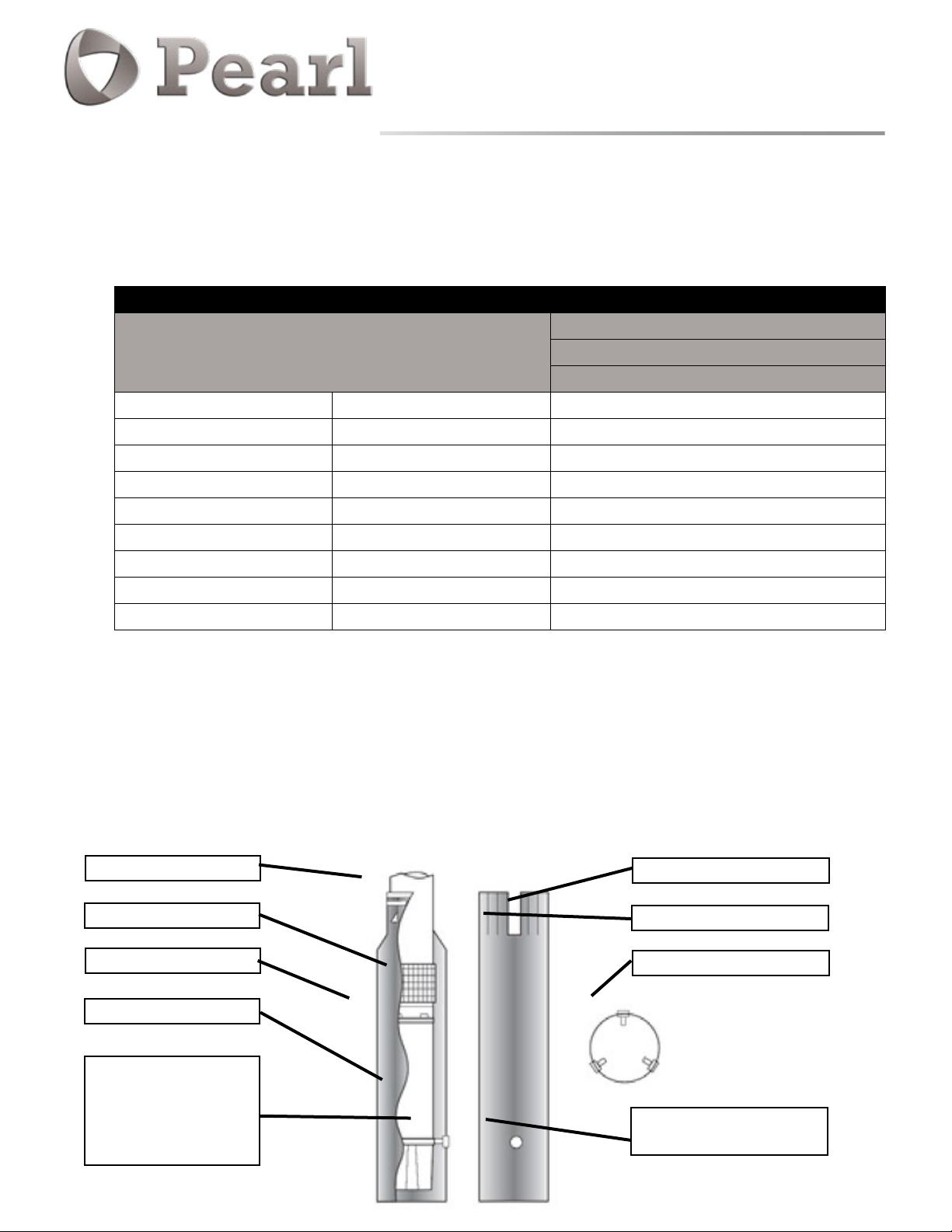
15. FLOW INDUCER SLEEVE
If the flow rate is less than specified or coming from above the pump, then a flow inducer sleeve must be used. A flow
sleeve is always required in an open body of water.
Figure shows a typical flow inducer sleeve construction.
Example : A four-inch motor and pump that delivers 60 GPM will be installed in a 8” well.
From Table 2
A 122 GPM flow would be required to maintain proper cooling in an 8” casing, as the 6” casing
requires a min flow of 55gpm then adding an 6” or smaller flow sleeve provides the required cooling.
Worm Worm clamps
4" Motor (1/2-10Hp)
0.98 ft/sec (0.3m/sec)
GPM (l/min)
Saw cuts
Intake
Flow inducer sleeve
Submersible motor
Centering bolt
Centering bolts must
be located on motor
casting. Do not locate
on stator shell
Notch out for cable guard
Lock nuts inside sleeve
Bottom view
Centering bolt hole
(3 required) 120°
Page 9

4MWP
4” Submersible Motors
16. HOT WATER APPLICATION
When the pump-motor operates in water hotter than 95°F (35°C), a flow rate of at least 11.5 ft/sec is required. When
selecting the motor to drive a pump in over 95°F (35°C) water, the motor horsepower must be de-rated per the
following procedure.
Using next Table to determine pump GPM required for different well or sleeve diameters.
If necessary, add a flow sleeve to obtain at least 11.5 ft/sec flow rate.
Table 4: Minimum GPM required for motor cooling in water above 95°F (35°C)
Minimum GPM required for motor cooling in water above 95°F (35°C)
4" Motor (1/2-10Hp)
Casing or Sleeve
I.D. Inches (mm)
11.5 ft/sec (3.2m/sec)
6" Motor
GPM (l/min)
4" 102 75 (283)
5" 127 330 (1244)
6" 152 650 (2450)
7" 178 86 (325)
8" 203 122 (461)
The table shows minimum flow rates, in GPM, for various well diameters and motor sizes
17. CONTROL BOX MOUNTING
Single phase submersible control boxes feature NEMA 3R enclosures for indoor or outdoor mounting. They should be
mounted in a vertical position as relay manufacturers recommend correct relay
positioning for proper, trouble-free operation.
Control boxes should be shaded from direct sunlight in areas where temperatures exceed 95°F (35°C) as excessive
heat may dry out capacitors and shorten their life. It is advisable to paint the enclosure white if outside in very hot,
sunny climates.
Page 10

L
38,17
-
0,12
+
0,13
23
±0,5
15
0
+
0,5
15,5
+
0,03
+
0,05
B
0,5
+
0
15
A
15,5
+
0,05
+
0,03
18. 4MWP 2 WIRE MOTOR DIMENSIONS
4MWP
4” Submersible Motors
0,12
Table 5: 4MWP 2 WIRE MOTORS
0,13
-
+
D
±0,5
C
38,17
23
L
4MWP DIMENSIONS
SINGLE PHASE MOTORS
Typ e
P2
Tipo
Tipo
[hp] [kW]
0.5/115v
0.5/230v
60 Hz
0.75
1
1.5
4MWP DIMENSIONS
Pos.
mm
Ø 15.5
+0.5
15
+0.5
23
38.17
-0.5
+0.05
-0
+0.13
-0.03
-0.12
A
B
C
D
L
[mm] [inch]
0.37 341
0.37 331
0.55 351
0.75 426
1.1 471
13.425
13.031
13.819
16.772
18.543
inch Pos.
+0.002
0.61”
0.591”
0.906”
1 1/2"
+0.02
+0.02
+0.005
-0.003
-0
-0.005
-0.02
E
F
G
Weight TW
Peso TW
Peso TW
[Kg] [lbs]
9.7
9.5
10.5
13.1
15.1
mm
+0.4
37.2
Ø 76.2
Ø 87.3
21.4 500
21 500
23.2 500
28.9 700
33.3 700
inch
1.465”
+.01
+0
-0.4
-0.1
+0.004
3"
3.437”
-0
+0.
-0
Axial thrust
Spinta assiale
Empuje axial
[lbf]
+0.016
-0.016
-0.004
5/16
”
24 UNF
M
8
E
F
37,2
±0,4
G
+
0,1
76,2
0
0
87,3
-
0,1
Page 11

L
23
±0,5
38,17
-
0,12
+
0,13
15
0
+
0,5
15,5
+
0,03
+
0,05
19. 4MWP 3 WIRE MOTOR DIMENSIONS
0,12
0,13
-
+
D
38,17
L
C
±0,5
23
B
0
0,5
+
15
A
15,5
+
0,05
+
0,03
4” Submersible Motors
Table 6: 4MWP 3 WIRE MOTORS
4MWP DIMENSIONS
SINGLE PHASE MOTORS
Typ e
60 Hz
3W
THREE PHASE MOTORS
Typ e
60 Hz
P2
[hp] [kW]
0.5
0.75
1
1.5
2
3
5
0.37 266
0.55 286
0.75 346
1.1 411
1.5 411
2.2 544
3.7 684
P2
[hp] [kW]
0.5
0.75
1
1.5
2
3
0.37 236
0.55 266
0.75 286
1.1 346
1.5 391
2.2 504
5.5
7.5
10
5.5 684
7.5 764
[mm] [inch]
[mm] inch]
4 614
L
10.472
11.26
13.622
16.181
16.181
21.417
26.929
L
9.291
10.472
11.26
13.622
15.394
19.843
24.173
26.929
30.079
4MWP
8.8
9.7
12.6
14.7
14.8
20.5
27.1
7.4
8.8
9.7
11.7
13.8
18.5
23.5
27.1
31.1
Weight GG
[Kg] [lbs]
19.4 500
21.4 500
27.8 700
32.5 700
32.7 700
45.2 1500
59.8 1500
Weight GG
[Kg] [lbs]
16.3 500
19.4 500
21.4 500
25.8 700
30.5 700
40.8 1500
51.9 1500
59.8 1500
68.7 1500
Axial thrust
[lbf]
Axial thrust
[lbf]
5/16
”
24 UNF
M8
E
F
37,2
G
76,2
87,3
±0,4
+
-
4MWP DIMENSIONS
Pos.
A
B
C
D
0,1
0
0
0,1
Ø 15.5
15
23
38.17
mm
+0.05
+0.5
+0.5
+0.13
inch Pos.
0.610 E
-0.03
0.591 F
-0
-0
-0.12
7
/8" G
1 1/2"
mm
37.2
Ø 76.2
Ø 87.3
+0.4
+.01
+0
-0.4
-0.1
inch
1.465
-0
3"
3 3/8"
Page 12

4MWP
4” Submersible Motors
20. SINGLE PHASE - MOTOR DATA
Table 8: 4MWP 2 WIRE MOTOR DATA
ELECTRICAL DATA 4MWP 2W
SINGLE PHASE MOTORS
P2 V
[hp] [kW]
0.5 0.37
0.75 0.55 230 1.5 6.3 6.9 4.3 0.65 1200 3450 0.82 47 25 3x14 5½
1 0,75 230 1.4 7.7 8.8 4.8 0.68 1500 3450 0.84 50 35 3x14 5½
1.5 1.1 230 1.3 11.8 12.7 4.7 0.7 2120 3450 0.85 53 40 3x14 5½
[V]
115 1.6 8.6 10 4.2 0.65 800 3450 0.88 46 80 3x14 5½
230 1.6 3.9 5 4.6 0.65 800 3450 0.88 46 20 3x14 5½
SF
Table 9: 4MWP 3 WIRE MOTOR DATA
ELECTRICAL DATA 4MWP 3W
[A]
In
In (SF)
Is/In Cs/Cn
[A]
P1
[W]N[min-1]
Cos j
h
%
C
[µF]Ø[AWG ]
LC
[ft]
SINGLE PHASE MOTORS
P2 V
[hp] [kW]
0.5 0.37
0.75 0.55 230 1.5 7.4 8.6 4.6 3.6 1100 3450 0.65 53 - 86-103 4x14 5½
1 0.75 230 1.4 8.0 9.8 5.5 2.9 1350 3450 0.68 58 - 105-126 4x14 5½
1.5 1.1 230 1.3 10.0 12.0 6.0 1.9 1800 3450 0.81 64 10 105-126 4x14 5½
2 1.5 230 1.25 10.5 12.3 5.3 2.3 2200 3450 0.95 69 20 105-126 4x14 5½
3 2.2 230 1.15 14.3 16.2 5.5 2.1 3100 3450 0.97 72 45 208-250 4x14 5½
5 3.7 230 1.15 22.2 25.5 5.5 1.8 5000 3450 0.99 74 2x40 270-324 4x14 8 ¾
P2: Rated output - Potenza nominale - Potencia nominal
V: Rated voltage - Tensione nominale - Tension nominal
SF: Service factor - Fattore di servizio - Factor de servicio
In: Rated current - Corrente nominale - Corriente nominal
In (SF): Service factor current - Corrente al fattore di servizio - Corriente al factor de servicio
Is/In: Locked rotor current/Rated current - Corrente avviamento/Corrente nominale Corriente de arranque/Corriente nominal
Cs/Cn: Locked rotor Torque/Rated Torque - Coppia avviamento/Coppia nominale Cupla de arranque/Cupla nominal
[V]
115 1.6 10.0 12.6 4.0 3.2 800 3450 0.71 48 - 250-300 4x14 5½
230 1.6 5.5 6.8 4.2 3.9 800 3450 0.62 46 - 59-71 4x14 5½
SF
[A]
In
In (SF)
Is/In Cs/Cn
[A]
P1
[W]N[min-1]
P1: Power consumption - Potenza assorbita - Potencia absorbida
N: R.P.M - Giri al minuto - Revoluciones por minuto
Cos φ: Power factor - Fattore di potenza - Factor de potencia
η: Eciency - Rendimento - Rendimiento
C: Capacitor - Condensatore - Capacidad del condensador
Ø: Cable section - Sezione del cavo - Sección del cable
LC: Cable length - Lunghezza del cavo - Longitud de cable
Cos j
100%
Load
h %
100%
LoadC1[µF]C2[µF]Ø[AWG ]LC[ft]
Page 13

4MWP
4” Submersible Motors
21. THREE PHASE - MOTOR DATA
Table 11: 4MWP 3 PHASE MOTOR DATA
ELECTRICAL DATA 4MWP
THREE PHASE MOTORS
P2 V
[hp] [kW]
0.5 0.37
0.75 0.55
1 0.75
1.5 1.1
2 1.5
3 2.2
5.5 4
7.5 5.5
10 7.5 460 1.15 15.4 16.9 7.1 3.9 9100 3450 0.74 82 4x14 11½ 11½
[V]
230 1.6 3.6 3.7 4.4 3.4 690 3450 0.48 54 4x14 5½ 5½
460 1.6 1.6 1.9 5.0 3.2 650 3450 0.54 57 4x14 5½ 5½
230 1.5 4.6 4.9 5.2 3.7 860 3450 0.47 63 4x14 5½ 5½
460 1.5 2.2 2.4 5.5 3.6 840 3450 0.48 65 4x14 5½ 5½
230 1.4 4.7 5.2 6.4 4.3 1200 3450 0.63 63 4x14 5½ 5½
460 1.4 2.6 2.8 5.8 4.2 1200 3450 0.59 63 4x14 5½ 5½
230 1.3 8.1 8.5 5.9 4.2 1800 3450 0.54 61 4x14 5½ 5½
460 1.3 3.6 3.9 6.7 4.1 1720 3450 0.60 64 4x14 5½ 5½
230 1.25 10.2 10.8 6.1 3.9 2290 3450 0.54 65 4x14 5½ 5½
460 1.25 4.6 4.9 6.7 3.8 2160 3450 0.59 69 4x14 5½ 5½
230 1.15 10.7 11.6 7.5 4.8 3100 3450 0.69 71 4x14 5½ 5½
460 1.15 5.6 6.0 7.1 4.8 3050 3450 0.68 72 4x14 5½ 5½
230 1.15 16.7 17.3 7.9 3.7 4300 3450 0.65 70 4x14 8 ¾ 8 ¾
460 1.15 7.2 7.6 7.4 4.0 5300 3450 0.75 75 4x14 8 ¾ 8 ¾
230 1.15 25.7 27.5 7.0 3.9 7260 3450 0.71 76 4x14 8 ¾ 8 ¾
460 1.15 12.0 13.0 7.5 3.8 7050 3450 0.74 79 4x14 8 ¾ 8 ¾
SF
[A]
In
In (SF)
Is/In Cs/Cn
[A]
P1
[W]
N
[min-1]
Cos j
100%
Load
h %
100%
Load
C
[µF]Ø[mm2]
LC
[ft]
Page 14

4” Submersible Motors
22. SINGLE PHASE MOTOR WINDING RESISTANCES
Table 13: 4MWP 1 PHASE 2 WIRE MOTOR WINDING RESISTANCES
ELECTRICAL DATA 2 WIRE
4MWP 2W SINGLE PHASE MOTORS
P2 V
[hp] [kW]
0.5 0.37
0.75 0.5 230 2.5
1.0 0.75 230 1.9
1.5 1.1 230 1.45
Table 14: 4MWP 1 PHASE 3 WIRE MOTOR WINDING RESISTANCES
ELECTRICAL DATA 3 WIRE
4MWP 3W SINGLE PHASE MOTORS
P2 V
[hp] [kW]
0.5 0.37
[V]
115 0.95
230 3.7
MAIN RESISTANCE START RESISTANCE
[V]
115 1.2 4.9
230 3.9 15
4MWP
WINDING RESISTANCE
0.75 0.5 230 3.0 10.8
1.0 0.75 230 2.4 9.9
1.5 1.1 230 1.8 9.1
2 1.5 230 1.9 5.7
3 2.2 230 1.2 2.5
5 3.0 230 0.8 1.5
Page 15

23. 4MWP THREE PHASE MOTOR WINDING RESISTANCES
Table 16: 4MWP 3 PHASE MOTOR WINDING RESISTANCES
ELECTRICAL DATA 60 Hz
4MWP THREE PHASE MOTORS
P2 V
[hp] [kW]
[V]
230 5.8
4MWP
4” Submersible Motors
WINDING RESISTANCE
0.5 0.37
0.75 0.5
1.0 0.75
1.5 1.1
2 1.5
3 2.2
460 25.6
575 39
230 3.9
460 17.3
575 26
230 2.4
460 13
575 19.7
230 2.2
460 8.9
575 14.6
230 1.5
460 6
575 9
230 1.3
460 5.1
575 7.7
230 0.83
5 3.0
7.5 5.0
10 7.5
460 3.3
575 5.2
230 0.6
460 2.35
575 3.7
460 2
575 3.2
Page 16

4MWP
4” Submersible Motors
24. MAXIMUM CABLE LENGTHS IN FT
Table 18: Single Phase 60Hz
Motor rating Copper Wire Size
Volts Hp 14 12 10 8 6 4 2 0 00 000 0000 250 300
115 0.5 100 160 250 390 620 960 1460 2160 2630 3140 3770
0.5 400 650 1020 1610 2510 3880 5880 8720
0.75 300 480 760 1200 1870 2890 4370 6470 7870 9380
1.0 250 400 630 990 1540 2380 3610 5360 6520 7780 9350
1.5 190 310 480 770 1200 1870 2850 4280 5240 6300 7620
2.0 150 250 390 620 970 1530 2360 3620 4480 5470 6700
230
3.0 120 190 300 470 750 1190 1850 2890 3610 4470 5550
5.0 180 280 450 710 1110 1740 2170 2680
7.5 200 310 490 750 1140 1410 1720
10 250 390 600 930 1160 1430 1760
15 270 430 660 820 1020 1260
Three Phase 60Hz
Motor rating Copper Wire Size
Volts Hp 14 12 10 8 6 4 2 0 00 000 0000 250 300
0.5 930 1490 2350 3700 5760 8910
0.75 670 1080 1700 2580 4190 6490 9860
1.0 560 910 1430 2260 3520 5460 8290
1.5 420 670 1060 1670 2610 4050 6160 9170
2 320 510 810 1280 2010 3130 4770 7170 8780
3 240 390 620 990 1540 2400 3660 5470 6690 8020 9680
230
460
575
5 230 370 510 800 1240 1900
7.5 230 360 570 890 1350 2030
10 270 420 660 1010 1520 1870
15 290 450 690 1040 1280 1540
20 350 530 810 990 1200 1450
25 280 430 650 800 970 1170 1340
30 350 540 660 800 970 1110 1270
0.75 2730 4350 6850
1.0 2300 3670 5770 9070
1.5 1700 2710 4270 6730
2 1300 2070 3270 5150 8050
3 1000 1600 2520 3970 6200
5 590 950 1500 2360 3700 5750
7.5 420 680 1070 1690 2640 4100 6260
10 310 500 790 1250 1960 3050 4680 7050
15 540 850 1340 2090 3200 4810 5900 7110
20 410 650 1030 1610 2470 3730 4580 5530
25 530 830 1300 1990 3010 3700 4470 5430
30 430 680 1070 1640 2490 3060 3700 4500 5130 5860
40 790 1210 1830 2250 2710 3290 3730 4250
50 640 980 1480 1810 2190 2650 3010 3420
60 830 1250 1540 1850 2240 2540 2890
1 3630 5800 9120
1.5 2620 4180 6580
2 2030 3250 110 8060
3 1580 2530 3980 6270
5 920 1480 2330 3680 5750
7.5 660 1060 1680 2650 4150
10 490 780 1240 1950 3060 4770
15 530 850 1340 2090 3260
20 650 1030 1610 2520 3860 5830
25 520 830 1300 2030 3110 4710
30 680 1070 1670 2560 3880 4770 5780 7030 8000
40 790 1240 1900 2860 3510 4230 5140 5830
50 1000 1540 2310 2840 3420 4140 4700 5340
60 850 1300 1960 2400 2890 3500 3970 4520
Page 17

4MWP
4” Submersible Motors
25. TIGHTENING MOTOR LEAD CONNECTOR SCREWS
4”Motors: 1.1 to 1.4 ft-lb. (1.5 to 1.9 N-m)
Screws tightening torques recommended for field assembly are shown. Rubber compression set within the first few
hours after assembly may reduce the screws torque. This is a normal condition which does not indicate reduced seal
effectiveness. Retightening is not required, but is permissible and recommended if original torque was questionable.
A motor lead assembly should not be reused. A new lead assembly should be used whenever one is removed from the
motor, because rubber set and possible damage from removal may prevent proper resealing of the old lead.
All motors returned for warranty consideration must have the lead returned with the motor.
26. SHAFT HEIGHT
Table 19: MOTOR SHAFT HEIGHTS
Motor Normal Shaft Height Dimension Shaft Height
4" 1 1/2" 38.17mm
27. CBWP CONTROL BOX DIMENSIONS
G
A
Free End Play
Min Max
1.508"
1.498"
H
G
C
B
38.30 mm
38.05 mm
CBWP BOX & KNOCKOUT DIMENSION
Pos. mm inch
A 124 4.9”
B 214 8.2”
C 74 2.9”
G PG 13.5 1/2” conduit
H PG 21 3/4” conduit
0.010" 0.045"
0.25 mm 1.14 mm
H
Volts/Hz Hp Motor kW Motor Start Cap. μF Volts
115/60 0.5 0.37 250-300 125
0.5 0.37 59-71 250
230/60
0.75 0.55 86-103 250
1 0.75 105-126 250
Page 18

28. CBWP CONTROL BOX DIMENSIONS
4MWP
4” Submersible Motors
H
G
A
Volts/Hz Hp Motor kW Motor Run Cap.μF Volts Start Cap.μF Volts
1.5 1.1 10 370 105-126 250
1.5 1.1 10 370 105-126 250
G
C
B
BOX & KNOCKOUT DIMENSION
Pos. mm inch
A 210 8.3”
B 249 9.8”
C 150 5.9”
G 34 1” Conduit
H 23
1
/2” Conduit
230/ 60
2 1.5 20 370 105-126 250
2 1.5 20 370 105-126 250
3 2.2 45 370 208-250 250
3 2.2 45 370 208-250 250
5 3.7 80 370 270-324 250
5 3.7 80 370 270-324 250
Page 19

29. 4CBWP - CONTROL BOX - WIRING DIAGRAMS
TO PREVENT HAZARD OF FATAL OR SERIOUS ELECTRIC SHOCK :
Connect this control enclosure, all metal plumbing, and the motor frame to the power supply grounding terminal
using copper wire complying wich electrical codes. A ground wire at least the size of power wires complies.
Smaller wire may comply under some conditions.
Permanently close all unused wiring operning in this and other equipment.
Switch off power to this circuit at the power supply panel (not in this control) before working on or around the
control, pipes, cable, pump or motor.
4MWP
4” Submersible Motors
Page 20

29. CBWP - CONTROL BOX - WIRING DIAGRAMS
INSTALLATION AND OPERATION:
Mounting – Be sure that the control box is mounted in a vertical position with the top side up. If it is
mounted in any other position, the starting relay may not function and the overload may trip.
Connections – The control box should be wired to the line and the motors as shown in the diagram.
The pump will not operate without this control box.
Operation without the control box will burn out the motor. Installation of this motor and control must
include circuit and component protection in compliance with U.S. National Electrical Code or Canadian
Electrical Code, Part.1
Protection – Trip of overload indicates a shorted capacitor, voltage problems, an overloaded or
locked pump, or the start relay should be replaced. Reset and analyse for tripping cause.
Do not remove or short out overload protection, since doing so is likely to cause motor burnout.
Use 75° C copper wires/conductors only, 14-10 AWG, tightening torque 20lbs*inch.
4MWP
4” Submersible Motors
For guarantee the Enclosure Type 3R need fix the box using 2 fixing holes.
0.5 – 0.75 1HP 60HZ 115/230 V
How to check the color code of a drop cable (Single-Phase 3-Wire Units)
With an ohmmeter measure:
Cable 1 to Cable 2, Cable 2 to Cable 3, Cable 3 to Cable 1
Find the highest resistance reading.
The lead not used in the highest reading is the yellow lead.
Use the yellow lead and each of the other two leads to get two readings:
Highest is the red lead.
Lowest is the black lead.
EXAMPLE:
The ohmmeter readings were:
Cable 1 to Cable 2 - 6 ohms Cable 2 to Cable 3 - 2 ohms Cable 3 to Cable 1 - 4 ohms
The lead not used in the highest reading (6 ohms) was Cable 3 so Cable 3 = Yellow
From the yellow lead, the highest reading (4 ohms) was To Cable 1 so Cable 1 = Red
From the yellow lead, the lowest reading (2 ohms) was To Cable 2 so Cable 2 = Black
Page 21

30. CBWP - CONTROL BOX - WIRING DIAGRAMS
TO PREVENT HAZARD OF FATAL OR SERIOUS ELECTRIC SHOCK :
Connect this control enclosure, all metal plumbing, and the motor frame to the power supply grounding terminal using copper wire complying wich electrical codes. A ground wire at least the size of power wires complies.
Smaller wire may comply under some conditions
Permanently close all unused wiring operning in this and other equipment.
Switch off power to this circuit at the power supply panel (not in this control) before working on or around the
control, pipes, cable, pump or motor.
INSTALLATION AND OPERATION:
Mounting – Be sure that the control box is mounted in a vertical position with the top side up. If it is mounted
in any other position, the starting relay may not function and the overload may trip.
Connections – The control box should be wired to the line and the motors as shown in the diagram.
The pump will not operate without this control box.
Operation without the control box will burn out the motor. Installation of this motor and control must include
circuit and component protection in compliance with U.S. National Electrical Code or Canadian Electrical Code,
Part.1
Protection – Trip of overload indicates a shorted capacitor, voltage problems, an overloaded or locked pump,
or the start relay should be replaced. Reset and analyse for tripping cause.
Do not remove or short out overload protection, since doing so is likely to cause motor burnout.
4MWP
4” Submersible Motors
Use 75° C copper wires/conductors only, 14-10 AWG, tightening torque 20lbs*inch.
For guarantee the Enclosure Type 3R need fix the box using 2 fixing holes.
CHECKING PROCEDURE: BE SURE POWER IS TURNED OFF:
A) OVERLOAD (Push reset button to make sure contacts are closed)
1. Ohmmeter setting: (Rx1).
2. Terminal connections: ohmmeter leads to overload terminals.
3. Ohmmeter reading: should not be over 0.5 ohms.
B) CAPACITOR (Disconnect one lead from each capacitor prior to checking)
1. Ohmmeter setting: (Rx1000).
2. Terminal connections: individual capacitor teminals.
3. Ohmmeter reading: pointer should swing toward zero then drift back toward infinity.
C) RELAY COIL (Disconnect lead from terminal 5)
1. Ohmmeter setting: (Rx1000).
2. Terminal connections: “5” and “2” on relay.
3. Ohmmeter reading: 4500-7000 ohms
D) RELAY CONTACT (Disconnect lead from terminal 1)
1. Ohmmeter setting: (Rx1).
2. Terminal connections: “1” and “2” on relay.
3. Ohmmeter reading: should be zero.
E) MAGNETIC CONTACTOR ONLY (Disconnect 1 coil lead)
1. Ohmmeter setting: (Rx100).
2. Check coil resistance: 1000-1400 ohms.
3. Remove contact cover and inspect contacts
Page 22

30. CBWP - CONTROL BOX - WIRING DIAGRAMS
2 HP 230V 60Hz BASIC 1.5 HP 230V 60Hz BASIC
4MWP
4” Submersible Motors
Page 23

30. CBWP - CONTROL BOX - WIRING DIAGRAMS
3 HP 230V 60Hz DELUXE 3 HP 230V 60Hz
4MWP
4” Submersible Motors
5 HP 230V 60Hz DELUXE 5 HP 230V 60Hz
Page 24

4MWP
4” Submersible Motors
31. THREE PHASE POWER UNBALANCE
A full three phase supply is recommended for all three phase motors, consisting of three individual transformers or one
three phase transformer. So-called “open” delta or wye connections using only two transformers can be used, but are
more likely to cause problems, such as poor performance overload tripping or early motor failure due to current
unbalance.
Transformer ratings should be no smaller than listed on Transformer Size Chart on the next page.
OPEN DELTA OR WYE FULL THREE PHASE
Checking and correcting rotation and current unbalance.
Establish correct motor rotation by running in both directions. Change rotation by exchanging any two of the three
1.
motor leads. The rotation that gives the most water flow is always the correct rotation.
After correct rotation has been established, check the current in each of the three motor leads and calculate the
2.
current unbalance as explained in 3 below. If the current unbalance is 2% or less, leave the leads as connected.
If the current unbalance is more than 2%, current read-ings should be checked on each leg using each of the
three possible hook-ups. Roll the motor leads across the starter in the same direction to prevent motor reversal.
3.
To calculate percent of current unbalance:
A. by three, yielding average current.
B. Pick the amp value which is furthest from the average current (either high or low).
C. Determine the difference between this amp value (furthest from average) and the average.
D. Divide the difference by the average. Multiply the re Add the three line amp values together.
E. Divide the sum sult by 100 to determine percent of unbalance.
Current unbalance should not exceed 5% at service factor load or 10% at rated input load. If the unbal-ance
4.
cannot be corrected by rolling leads, the source of the unbalance must be located and corrected. If, on the three
possible hookups, the leg farthest from the average stays on the same power lead, most of the unbalance is
coming from
the power source. However, if the reading farthest from average moves with the same motor lead, the primary
source of unbalance is on the “motor side” of the starter. In this instance, consider a damaged cable, leaking
splice, poor connection, or faulty motor winding
Page 25

31. THREE PHASE POWER UNBALANCE
Phase designation of leads for CCW rotation viewing shaft end.
To reverse rotation, interchange any two leads
Phase 1 or “A” – Black Motor Lead or T1
Phase 2 or “B” – Yellow Motor Lead or T2
Phase 3 or “C” – Red Motor Lead or T3
Notice: Phase 1, 2 and 3 may not be L1, L2 and L3.
4MWP
4” Submersible Motors
Example:
T1 = 51 amps + T1 = 50 amps +
T2 = 46 amps + T2 = 49 amps +
T3 = 53 amps = T3 = 51 amps =
Total = 150 amps Total = 150 amps
150/3 = 50 amps 150/3 = 50 amps 150/3 = 50 amps
50-46 = 4 amps 50-49 = 1 amps 50-48 = 2 amps
4/50 = 0.08 or 8% 1/50 = 0.02 or 2% 2/50 = 0.04 or 4%
32. TRANSFORMER SIZES
A full three phase supply is recommended for all three phase motors, consisting of three phase individual transformers
or one three phase transformer.
“Open” delta or wye connections using only two transformers can be used, but are more likely to cause problems from
current unbalance.
Transformer ratings should be no smaller than listed in the table for supply power to the motor alone.
T1 = 50 amps +
T2 = 48 amps +
T3 = 52 amps =
Total = 150 amps
Page 26

32. TRANSFORMER SIZES
A full three phase supply is recommended for all three phase motors, consisting of three phase individual transformers
or one three phase transformer.
“Open” delta or wye connections using only two transformers can be used, but are more likely to cause problems from
current unbalance.
Transformer ratings should be no smaller than listed in the table for supply power to the motor alone.
Table 20: TRANSFORMER SIZING
4MWP
4” Submersible Motors
KVA Rating (smallest) For Each Transformer
HP kW Required kVa
1.5 1.1 3.0 2.0 1.0
2 1,5 4.0 2.0 1.5
3 2.2 5.0 3.0 2.0
5 3.7 7.5 5.0 3.0
7.5 5.5 10 7.5 5.0
10 7.5 15 10.0 5.0
33. POWER SUPPLY BY A GENERATOR
Attention: the applicable tolerances from main supply must also be applied by power supply via generators
When operating a motor via a generator please bear in mind that the starting current of the motor is five times the
nominal motor current and that mean power factor of 0.6 for starting can be expected.
Also make sure that a sufficient generator power is permanently available and that for
starting the voltage must be at least 65% of the nominal motor Name plate voltage.
Open WYE or D 2
Transformers
Closed WYE or D 3
Transformers
Page 27

4MWP
4” Submersible Motors
INSULATION TESTING
34.
For the necessary inspections and insulation testing one tool is required:
Insulation measuring tester (Megaohmeter) unit 5OOv test, display up to min 200 M Ohm .
The correct execution of the junction (hermetic sealing) can be verified testing it under water for at least 15 min and
measuring with the Megaohmeter the insulation resistance between the metal recipient, filled with water (or water
itself) and each of the phase wires of the cable connected to the motor.
For a new motor the correct measurement has to be at least 200 M Ohm.
Another measure has to be done before installing the motor / pump in the place of use:
1
2
The exact values have to be at least 200 M Ohm for a new motor, and 20 M Ohm with a used motor installed.
It is always suggested to repeat this operation various times while lowering the motor/pump in the well.
connect a measuring cable to the ground lead
connect the other measuring cable to each conductor of the connected motor cable.
35. RESISTANCE OF THE DROP CABLE
The values below are for copper conductors. If aluminum conductor drop cable is used, the resistance will be higher.
To determine the actual resistance of the aluminum drop cable, divide the ohm readings from this chart by 0.61.
This chart shows total resistance of cable from control to motor and back.
Resistance in ohms per 100 ft of Wire @ 50 °F
Table 22: DROP CABLE RESISTANCE
AWG WIRE SIZE (COPPER) Reisitance Ohms MCM WIRE SIZE (COPPER) Reisitance Ohms
14 0.544 250 0.0088
12 0.338 300 0.0073
10 0.214 350 0.0063
8 0.135 400 0.0056
6 0.082 500 0.0044
4 0.052 600 0.0037
2 0.032 700 0.0032
0 0.021
00 0.017
000 0.013
0000 0.010
When measured through the drop cable, the resistance of the drop cablemust be subtracted from the ohmmeter
readings to get the winding resistance of the motor
Page 28

36. BOLT TORQUE SETTINGS
Table 23: TORQUE SETTING
Bolt Size Torque Setting in Nm (ft-lb)
4MWP
4” Submersible Motors
Steel 8.8 Stainless Steel 304-316/904
M6
M8
M10
M12
M14
M16
M18
M20
9 (6.638) 7 (5.163)
Steel 8.8 Stainless Steel 304-316/904
23 (16.964) 17 (12.539)
Steel 8.8 Stainless Steel 304-316/904
45 (33.190) 33 (24.340)
Steel 8.8 Stainless Steel 304-316/904
83 (61.218) 74 (54.580)
Steel 8.8 Stainless Steel 304-316/904
132 (97.3580) 119 (87.770)
Steel 8.8 Stainless Steel 304-316/904
200 (147.51) 183 (134.97)
Steel 8.8 Stainless Steel 304-316/904
275 (202.83) 260 (191.77)
Steel 8.8 Stainless Steel 304-316/904
390 (287.65) 370 (272.90)
WATER SYSTEMS
PD WATER SYSTEMS
3000 W. 16 Ave. Miami, FL 33012.
TEL: (954) 474 9090 FAX: (954) 889 0413
www.pdwatersystems.com | pdwatersystems
 Loading...