

Page 1

OBDtrac Dongle Getting Started
Version:1.01.01
Date:2011/12/12
© 2007 ORION Technology LTD. All rights reserved. 1/40
Page 2

Table of Contents
1. OBDtrac Dongle Hardware Introduction...............................................................3
I. Package contents:...........................................................................................3
II. Front panel: ....................................................................................................4
III. Rear panel:......................................................................................................4
IV. Product Installation: .......................................................................................5
V. Basic Configuration .......................................................................................6
2. Configuration by Hyper Terminal ..........................................................................8
I. Hardware and Software preparation ..............................................................8
II. Basic Configuration ..................................................................................... 11
III. GPRS Connection Configuration.................................................................12
IV. Gateway Server Configuration.....................................................................19
V. Function Variables Configuration – .............................................................20
VI. Function Variables Configuration – Mileage Report...................................21
VII.Function Variables Configuration – Idle Report..........................................23
VIII.Function Variables Configuration – Speed Limit Report............................25
IX. Running in Normal Mode ............................................................................27
3. Update firmware by Hyper T e rminal ................................................................... 30
4. Update firmware over the air (OTA) by GPRS....................................................32
5. OBDtrac Dongle troubleshooting guideline.........................................................34
6. OBDtrac Dongle Wiring Diagram........................................................................38
© 2007 ORION Technology LTD. All rights reserved. 2/40
Page 3
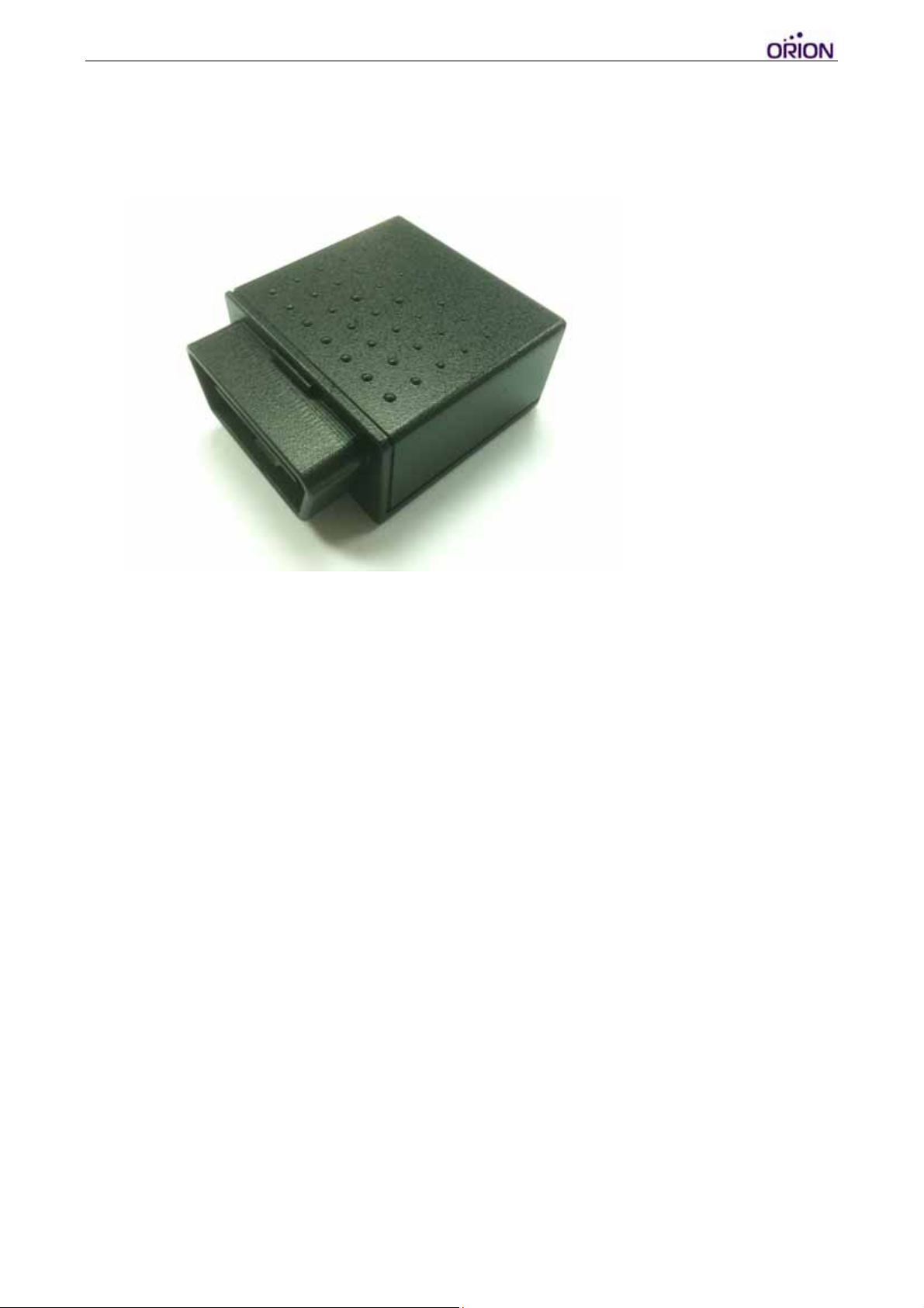
1. OBDtrac Dongle Hardware Introduction
I. Package contents:
1. OBDtrac Dongle x 1 (with Li-ion backup battery)
2. OBDII Port Extension Y-Cable
*Y Cable PHOTO
© 2007 ORION Technology LTD. All rights reserved. 3/40
Page 4
II. Front panel:
1. OBDII Connection Jack
*PHOTO
III. Rear panel:
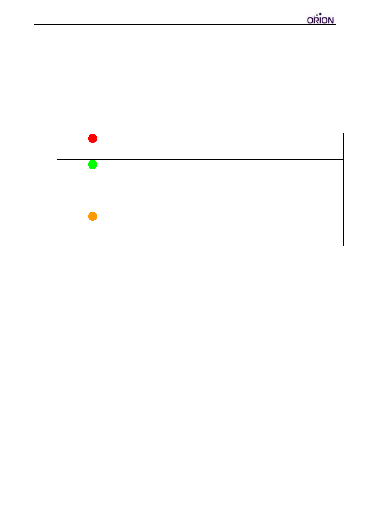
1. LED indicators
PWR
GSM
GPS
OFF: Power OFF
Flash: Power ON
OFF: GSM module OFF or Error
Flash: No SIM Card, Searching networks (0.25sec ON 0.5sec OFF)
Flash: GSM registered (0.5sec ON 0.5sec OFF)
Flash: GPRS connecting (0.25sec ON 0.25sec OFF)
ON: Socket session online (connect to Gateway Server)
OFF: GPS module OFF or Error
Flash: Searching GPS signal
ON: GPS fixed
*PHOTO
© 2007 ORION Technology LTD. All rights reserved. 4/40
Page 5
IV. Product Installation:
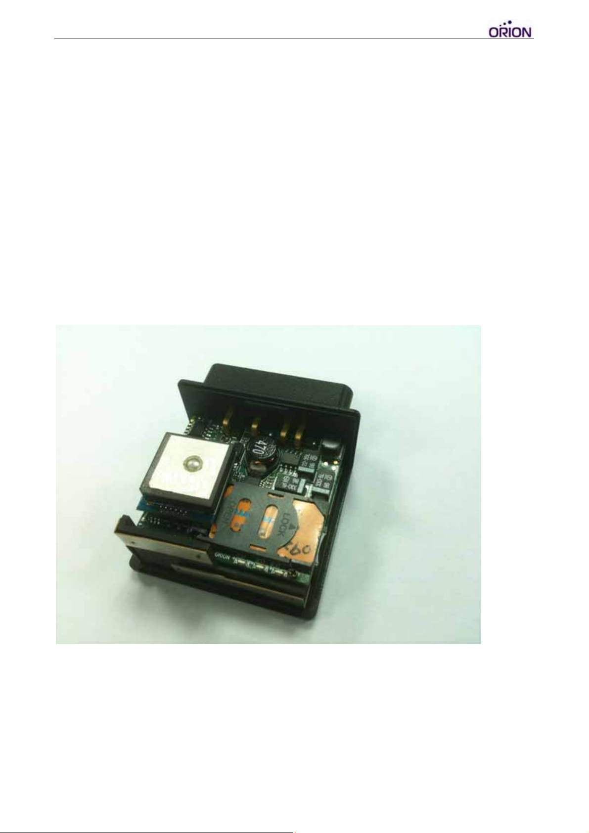
‐ Remove the cover by gently sliding backwards from the device itself.
‐ Insert SIM card into the card holder.
‐ Secure the cover back to its original position.
‐ Since the GPS module is still being fine tuned, there may be position fix
issues if the device is plugged directly onto the OBDII port and hidden
within the vehicle. It is recommended to use the Y cable included to test
the device for more exposure to open sky, once the device is plugged into
the vehicle through Y cable, the device should power up immediately.
© 2007 ORION Technology LTD. All rights reserved. 5/40
Page 6

V. Basic Configuration
‐ Basic configuration of the device can be done by using the Orion protocol
command $SetCFG via SMS by a mobile device. The command syntax is
as follows:
$SetCFG,<seq>,<pw>,<APN>,<GPRS username>,<GPRS
password>,<server IP>,<server port>,<GPRS enable>,<GPRS report
interval>,<GPRS data mode>,<power control>&
‐ Example of the $SetCFG command would be:
$SetCFG,1234,0000,internet,,,211.79.38.93,9996,YES,START,30,0,0&
‐ Once device configuration setup is complete, send another command
$ATR to the device in order to search and reset the device for the vehicle’s
OBDII protocol. The command syntax is as follows:
$ATR,<seq>,<pw>,<Initial Mileage>&
‐ Example of the $ATR command would be:
$ATR,1234,0000,1000&
Note: 1000 is an example value of initial mileage. Once entered, the total
mileage counter shown in the event reports will start incrementing from 1000.
Important: The return message for the $ATR command must display
“DONE” (after an initial return of “OK” for receiving the command). If the
message returns “MIL” or “FAIL”, they both indicate failure to input the vehicle
protocol or mileage value. The ATR return message can take up to 5 minutes
to report back depending on the vehicle protocol search, do not send $ATR
again consecutively during this period of search process.
Example of $ATR return messages:
$ATR,1234,DONE,020101000432& -> ATR command input is successful
$ATR,1234,MIL,020101000432& -> Previous input is not reset
$ATR,1234,FAIL,020101000432& -> ATR command input failed
© 2007 ORION Technology LTD. All rights reserved. 6/40
Page 7

‐ Use the command $Actgetpos,1234,0000& to double check if the mileage
value has been properly entered. The mileage value within the returned
LGPS message must be correct in order to deem the ATR configuration
successful.
Note: $ActGetPos return message will display not only the mileage value but
also the speed, RPM, and coolant temperature as well. Make sure all the
OBD values are correct when the vehicle is stationary before allowing the
vehicle to begin its trip.
Example of $LGPS return message:
$LGPS,120,261011092752,A,12131.0365,E,2502.9594,N,7,27,216,37.0,100
0.0,6308,79C,8,0,111026092753&
1000.0 = Mileage input
6308 = RPM
79C = Coolant temperature value
‐ Once all the configuration steps are completed, OBDtrac Dongle will begin
tracking and sending position event reports along with the predefined
OBDII information.
© 2007 ORION Technology LTD. All rights reserved. 7/40
Page 8
2. Configuration by Hyper Terminal
I. Hardware and Software preparation
1. Insert SIM card. Use the configuration RS-232 cable (DB-9) to connect
OBDtrac Dongle to a PC COM port.
2. Open Hyper Terminal (or other terminal program) at Windows Start
Menu:
All Programs\Accessories\Communications\Hyper Terminal.
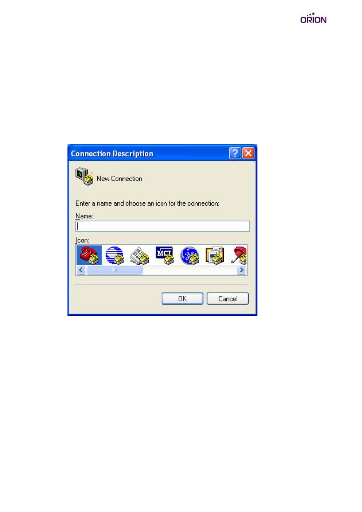
3. Add a new connection, enter a name as desired. Click “OK” and select
the COM Port for the OBDtrac connection.
© 2007 ORION Technology LTD. All rights reserved. 8/40
Page 9
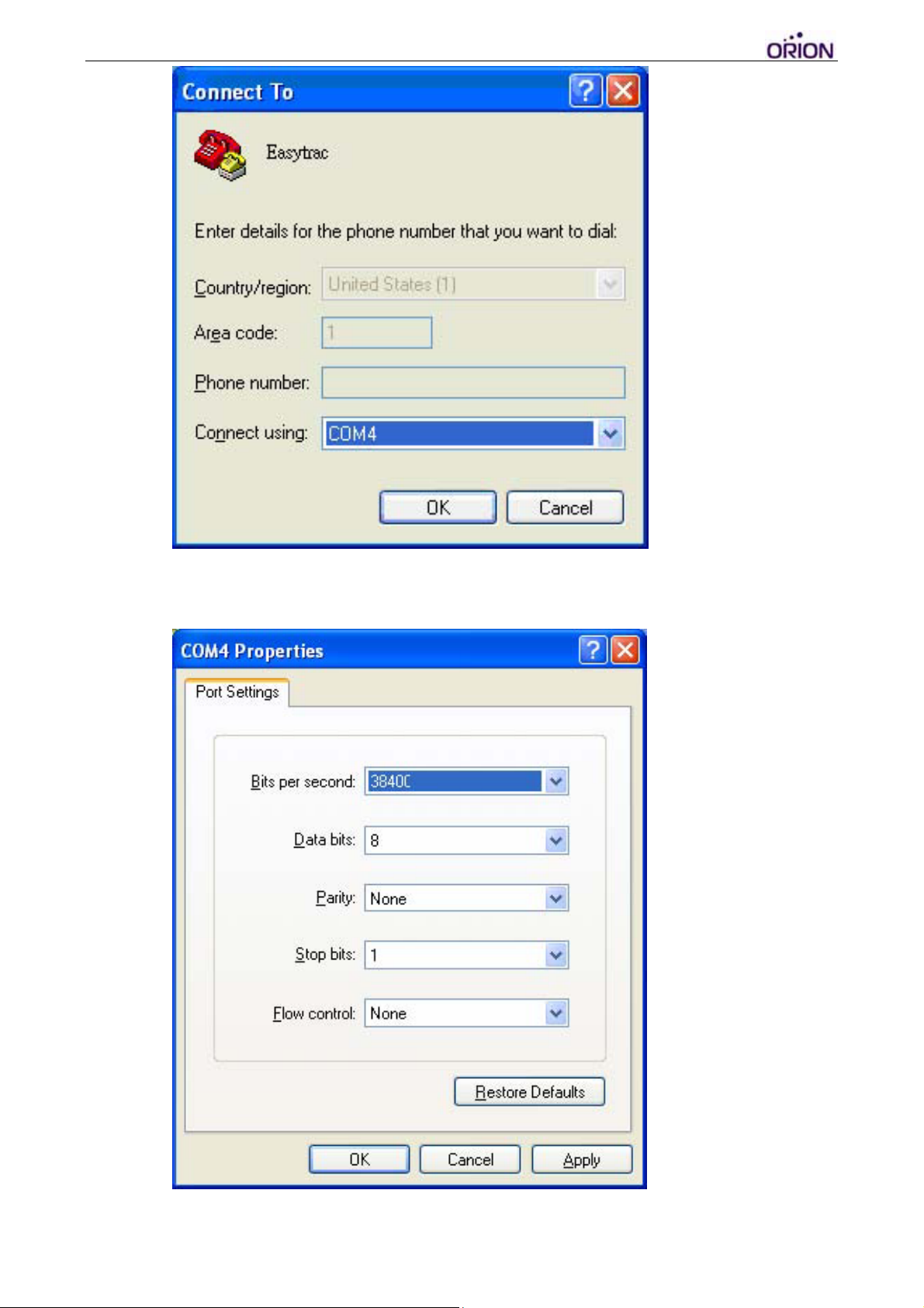
4. Set the Baud rate as 115200 bps and Flow control as none. Press “OK”.
5. Connect the 10pin cable to OBDtrac.
6. Connect the 10pin cable power-plug to the AC adapter and press the
© 2007 ORION Technology LTD. All rights reserved. 9/40
Page 10

‘ESC’ key of the PC keyboard within 3 second after the tracker is
powered on and starts showing text messages on the Hyper Terminal
screen (The tracker itself may need to be slightly shaken to power up if
the tracker is originally set to vibration power control mode). In doing
so, OBDtrac will enter ‘Debug Mode’ (Configuration Mode).
[]
- Version : 0.12
- Serial Number : BH1234567890
- Unit ID : 1000000001
- IMEI :
$>
7. If you do not see the above messages on the Hyper Terminal screen,
please check the settings of Hyper Terminal and reconnect the power
adapter, or press the RESET button on the OBDtrac rear panel.
Otherwise, please send an email to [email protected]
for
technical support.
© 2007 ORION Technology LTD. All rights reserved. 10/40
Page 11
II. Basic Configuration
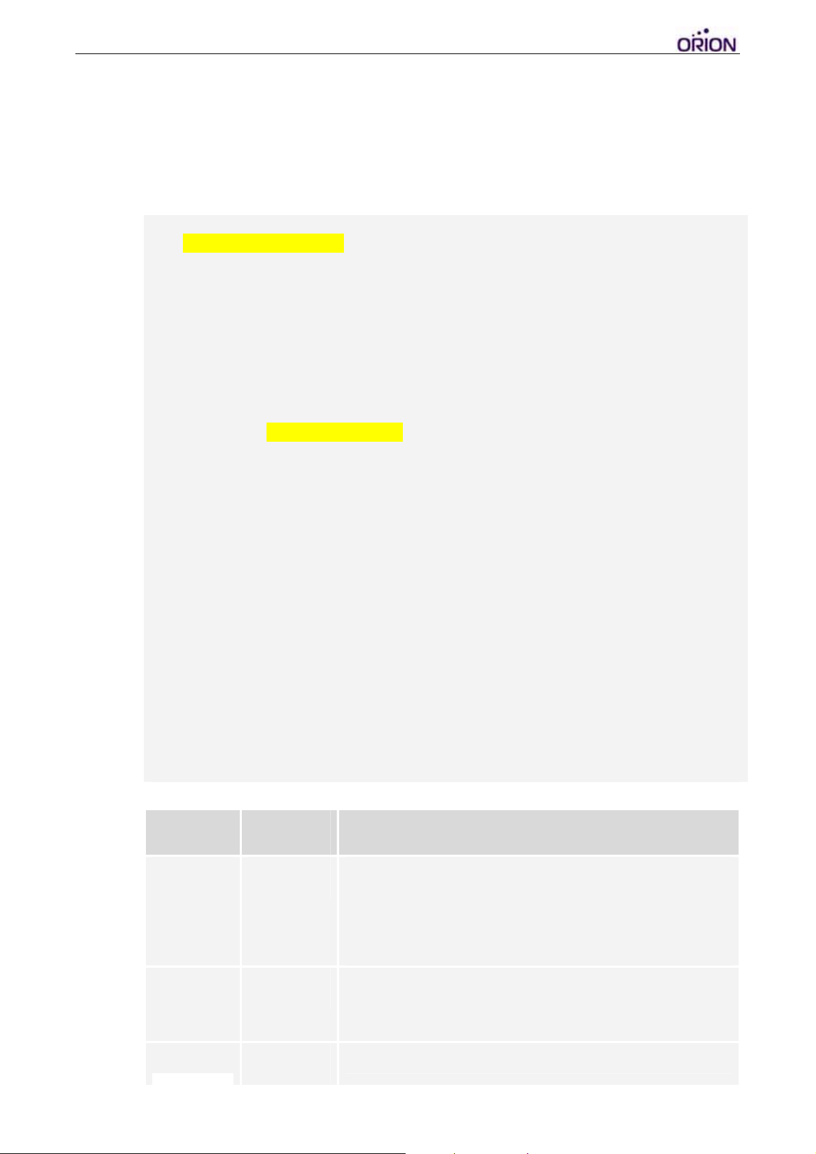
1. Use ‘SCFG’ command to enter ‘Main Setting Menu’. Then type ‘1’ to
enter ‘Basic Setting Menu’. For initialization or regular application, no
basic setting needs to be changed.
$>scfg <Press Enter>
Main Setting Menu :
1. Basic Setting
2. GSM/GPRS Connection Setting
3. Gateway Server Setting
4. Function Variables Setting
5. Report Settings Setting
E. Exit
Selection ? 1 <Press Enter>
Basic Setting Menu :
1. Firmware Version : 0.7
2. UnitID : 1000000001 : [0000000000-4294967296]
3. User Password : 0000
5. COM1 Baudrate : 38400 : [115200|38400|19200|9600|4800]
7. Sync RTC with GPS Time : YES
Time Zone of RTC : GMT+0
C. GPS Fix Timeout : 300 : [60-65535]
D. Vibration Timeout : 60 : [30-65535]
G. Power Control : 1 : [0(Disabled)|1(PowerOff)|2(Standby)|3(Sleep)|4(Deep
Sleep)]
H. Event Mask(1) : FFFFFFFF
I. Event Mask(2) : FFFFFFFF
E. Exit
Selection ?
Basic Setting Menu :
Field Mandatory Description
UnitID
Password
COM1
5
5
5
Device Unit ID. Default value is the same as the serial
number.
Range from ‘0000000000’ to ‘4294967296’. Other
characters are not allowed. Maximum: 10 digits
Default value : ”0000”.
Range from “0000” to “9999”.
Default value: “38400”
© 2007 ORION Technology LTD. All rights reserved. 11/40
Page 12

Baud rate
[115200|57600|38400|19200|9600|4800]
Sync RTC
with GPS
Time
Time Zone
Offset
GPS Fix
Timeout
Vibration
Timeout
Power
Control
Event Mask
(1)
5
5
5
5
5
YES: To enable the tracker to synchronize RTC Time with
GPS UTC Time according to the Time Zone Offset.
NO: To disable the tracker to synchronize RTC Time with
GPS UTC Time.
Format is +hh:mm or -hh: mm
GPS Timeout setting (sec) when every time the schedule
timer wakes up the OBDtrac Basic
Vibration Timeout to shut down OBDtrac Basic to enter
deep sleep mode
Control power off shut down mode, 0 = disable, 1 = enable
power off mode, 2 = standby mode, 3=sleep mode, 4=
deep sleep mode, functional only in conjunction with
VACCON mode in GSM/GPRS connection settings.
Configure event mask bits to enable/disable event
transmissions. Details refer to 970817T007 Event Mask
App Note
Event Mask
(2)
Configure event mask bits to enable/disable event
transmissions. Details refer to 970817T007 Event Mask
App Note
2. When you finish the ‘Basic Settings’, type ‘E’ to return to ‘Main Setting
Menu’.
III. GPRS Connection Configuration
1. Type ‘2’ to enter ‘GSM/GPRS Connection Setting Menu’. For
initialization or regular application, no setting of this menu needs to be
changed.
Main Setting Menu :
1. Basic Setting
2. GSM/GPRS Connection Setting
3. Gateway Server Setting
4. Function Variables Setting
5. Report Settings Setting
E. Exit
Selection ? 2 <Press Enter>
© 2007 ORION Technology LTD. All rights reserved. 12/40
Page 13

GSM/GPRS Connection Setting Menu :
1. Switch Mode : GPRS : [AUTO|GPRS|LOG|SMS]
2. GPRS Reconnect (min) : 3 : [2-65535]
3. SMS Duration (sec) : 180 : [180-65535]
4. SIM PIN1&2 Setting
SIM PIN1 :
SIM PIN2 :
5. GPRS Connection Setting
6. SMS Connection Setting
7. Enable Roaming : NO : [YES|NO]
8. Roaming Profile Settings
A. Enable RGTK/RMTK : YES : [YES|NO]
E. Exit
Selection ?
GSM/GPRS Connection Setting Menu :
Field Mandatory Description
Switch
Mode
GPRS
Reconnect
5
5
GPRS : Set the tracker to send reports by GPRS
connection only. But the tracker can receive commands
over GPRS from the server and to receive commands by
SMS from the mobile phone as well.
LOG : Set the tracker to send log reports only.
SMS : Set the tracker to send reports and receive
commands by SMS only. All event reports are supported
in SMS mode. It helps to use the tracker in the area
without GPRS coverage. Multiple protocol commands and
event reports are can be in one SMS as long as the size
less than 140 Bytes.
AUTO : Set the tracker to send reports by GPRS mainly
and to send reports by SMS as backup when the GPRS
connection fails.
The reconnecting time duration to open GPRS
connection. In GPRS Mode, After retrying N minutes with
error, the tracker will reboot and do it over. In AUTO Mode,
the tracker will switch to SMS mode and send ‘$RMTK’
SMS as a backup solution.
Range from “2” to “65535”. The unit is ‘minute’
Default Value=”2”
Tip: Enlarge this number properly according to the
GSM/GPRS environment can reduce the rebooting. In
some countries, it takes longer to open a GPRS
connection.
SMS
Duration
The time duration to stay in SMS mode when the
SwitchMode is set to ‘AUTO’ mode. After the duration, the
© 2007 ORION Technology LTD. All rights reserved. 13/40
Page 14

tracker will switch back to GPRS mode automatically.
Default Value = “180”. The unit is ‘second’.
Range from “180” to “65535”
Tip: Set this number smaller will let the tracker back to
GPRS mode as soon as possible. Enlarge the ‘SMS
Report Interval’ in the meantime (Ex. 2 hrs = 3600
seconds). It can reduce SMS cost accordingly.
SIM PIN1
SIM PIN2
Enable
Roaming
Roaming
Profile
Setting
Enable
RGTK/
RMTK
5
PIN1 of the SIM card to be used in the tracker
Default Value = “”.
PIN2 of the SIM card to be used in the tracker
Default Value = “”.
YES : Enable roaming to any network as long as the SIM
card support it.
NO : Disable roaming
Default Value = “NO”
Set roaming profile configurations and roaming event
masks.
YES: Generate the latest GPS position and send it as
$RGTK event with highest priority
NO: No $RGTK event will be generated because all GPS
position will be $LGTK and will be sent by FIFO sequence
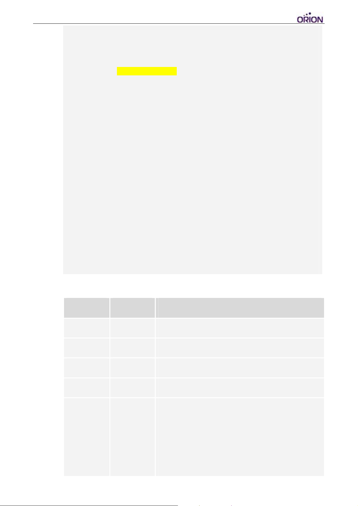
2. Type ‘5’ to enter ‘GPRS Connection Setting Menu’. T he GPRS
connection parameters are provided by the GSM operator. Note: All
GPRS connection parameters have to be correct, otherwise the
tracker cannot open GPRS connection successfully.
GSM/GPRS Connection Setting Menu :
1. Switch Mode : GPRS : [AUTO|GPRS|LOG|SMS]
2. GPRS Reconnect (min) : 3 : [2-65535]
3. SMS Duration (sec) : 180 : [180-65535]
4. SIM PIN1&2 Setting
SIM PIN1 :
SIM PIN2 :
5. GPRS Connection Setting
6. SMS Connection Setting
© 2007 ORION Technology LTD. All rights reserved. 14/40
Page 15
7. Enable Roaming : NO : [YES|NO]
8. Roaming Profile Settings
A. Enable RGTK/RMTK : YES : [YES|NO]
E. Exit
Selection ? 5 <Press Enter>
GPRS Connection Setting Menu :
1. GPRS Dial Number :
2. GPRS User Name :
3. GPRS Password :
4. GPRS APN : internet
5. GPRS Enable : START : [STOP|START|ACCON|VACCON]
6. GPRS Report Interval (sec) : 30 : [10-65535]
7. GPRS SYNC Interval (sec) : 300 : [0(Disable)|300-65535]
8. GPRS Resync Interval (min) : 1 : [0(Disable)|1(Once)|5-65535]
9. GPRS Filter : NO : [YES|NO]
A. GPRS DNS : 0.0.0.0
B. GSM Not Ready Re-Connect Time (sec) : 210 : [210-65535]
C. GPRS Not Ready Re-Connect Time (sec) : 300 : [300-65535]
D. Protocol : TCP : [TCP|UDP]
F. Require Server ACK : NO : [YES|NO]
G. Include Cell ID Info in Report : NO : [YES|NO]
H. Nonstop GPRS Tr acking: NO : [YES|NO]
J. Binary Report: NO : [YES|NO]
E. Exit
Selection ?
GPRS Connection Setting Menu :
Field Mandatory Description
Dial Number
User Name
Password
APN
GPRS
Enable
(Track Mode)
5
5
GPRS dialup phone number.
GPRS Login User Name
GPRS Login Password
Access Point Name
STOP : Stop the GPRS tracking action. The tracker
sends SYNC packet by SYNC interval to the Gateway
server to keep alive.
START : The tracker sends GPS data over GPRS as
long as it is powered ON. No matter the ACC (Ignition)
is ON or OFF.
ACCON : The tracker sends GPS data over GPRS only
when the ACC is ON. When the ACC is OFF, the tracker
© 2007 ORION Technology LTD. All rights reserved. 15/40
Page 16

sends SYNC packet by SYNC interval to the Gateway
server to keep alive.
VACCON : Report RGTK at either LGSK (vibration on)
or LACN (engine on), and stop reporting RGTK when
both LGEK (vibration off) and LACF (engine off ) events
appear. If actual ACC is not connected, report RGTK
between LGSK and LGEK vibration events.
Report
Interval
SYNC
Interval
Resync
Interval
5
5
5
GPS data Report Interval. The unit is ‘second’.
Default Value = “30”.
Range from [10-65535].
SYNC packet Interval: The unit is ‘second’
Range from [0(Disable)|300-65535]. “0” means to
disable SYNC packet.
Default = 300 Seconds. Set longer Sync Interval to save
GPRS cost.
Note: The SYNC packet is now only applicable in
‘STOP’ mode or when ACC=OFF in ‘ACCON’ mode or
‘VACC’ mode.
Compulsory SYNC packet Interval: The unit is ‘minute’
Range from [0(Disable)|1(Once)|5-65535]. “0” means to
disable SYNC packet. “1” means the tracker only sends
a SYNC packet every time it open a new GPRS
session.
Default value = 1 (Once)
The Resync packet is now applicable in ‘START’ mode
or when ACC=ON in ‘ACCON’ more or ‘VACC’ mode.
Filter
DNS
GSM Not
Ready
5
5
YES : Filter the invalid GPS data. Only send the valid
GPS data
NO : Not Filter GPS data. Send all GPS data, no matter
the GPS data is valid or invalid.
DNS Server IP address
If the device can’t register to GSM network, the tracker
will wait ‘GSM Not Ready Re-Connect Time’ to reboot.
© 2007 ORION Technology LTD. All rights reserved. 16/40
Page 17

Re-Connect
Time
The unit is ‘second’.
Default Value = “210”.
Range from “210” to 65535”.
GPRS Not
Ready
Re-Connect
Time
Protocol
Require
Server ACK
ACK Timeout
5
5
5
5
If the device register to GSM network but can’t open
GPRS connection successfully, the tracker will wait
‘GPRS Not Ready Re-Connect Time’ to reboot. The unit
is ‘second’.
Default Value = “300”.
Range from “300” to 65535”.
TCP: To use TCP/IP in GPRS communication
UDP: To use UDP/IP in GPRS communication
Default = TCP
YES: To require the Gateway Server send back an ACK
for every event report for confirmation to send next one.
NO: Disable requiring Server ACK of every event report
Default = NO
Time to wait for the Sever ACK. Everytime when
timeout, the tracker will send the event report again.The
unit is ‘second’.
Retry
Include Cell
ID Info
Nonstop
GPRS
Tracking
5
5
Range from [5-65535]
How many times to retry to send the event report. If it
keeps failing, the tracker will re-open the GPRS
connection and do it over. The unit is ‘count’.
Range from [1-65535]
YES: To include Cell ID information in every event
report. If enabled, two new columns [PLMN] (Network
ID), [Cell ID] (Base station ID) will be added into every
event report.
NO: Not to include Cell ID information in all event
reports.
This feature is applicable to Switch Mode = ‘AUTO’.
YES: When the tracker switches to SMS, it still logs
GPS data in flash memory according to GPRS tracking
interval. All data will be sent when the GPRS is back.
This features helps to generate complete route even in
the area without GPRS.
NO: When the tracker switches to SMS, it only sends
the GPS data according to SMS tracking interval
© 2007 ORION Technology LTD. All rights reserved. 17/40
Page 18

Binary
Report
Notes: This console menu corresponds to ORION Protocol commands:
$SetGPRSConfig, $SetConnection,
YES: Enable binary encryption report mode
NO: Disable binary encryption report mode
For more details refer to “binary report app note”
3. When you finish the ‘GPRS Connection Settings’, type ‘E’ to return to
‘GSM/GPRS Connection Setting Menu’. Then type ‘E’ to return to
‘Main Setting Menu’.
© 2007 ORION Technology LTD. All rights reserved. 18/40
Page 19
IV. Gateway Server Configuration
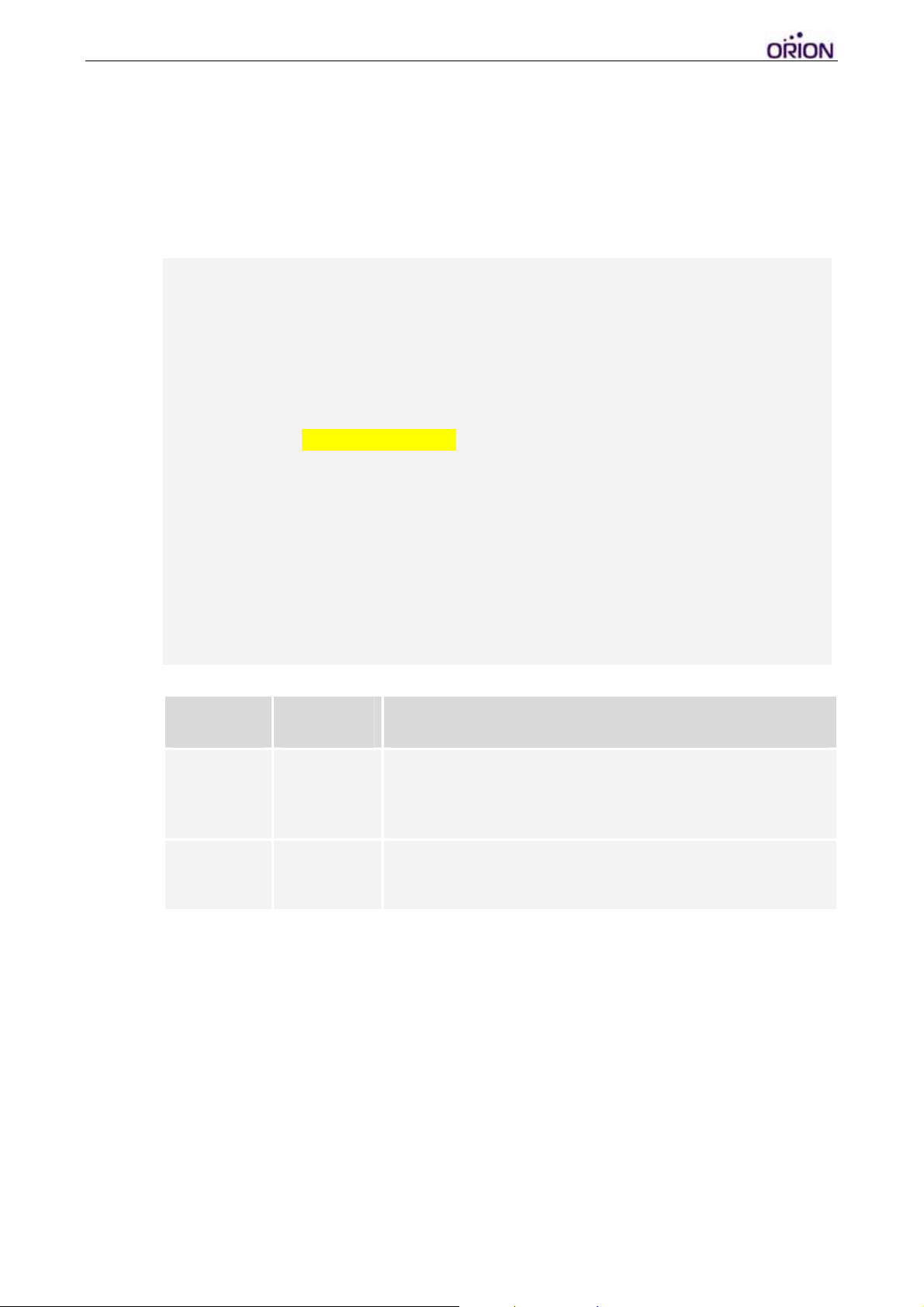
1. Type ‘3’ to enter ‘Gateway Server Setting Menu’. Note: The Gateway
Server settings have to be 100% accurate, otherwise the tracker will
be unable to open GPRS connections and build a socket session with
the Gateway Server correctly.
Main Setting Menu :
1. Basic Setting
2. GSM/GPRS Connection Setting
3. Gateway Server Setting
4. Function Variables Setting
5. Report Settings Setting
E. Exit
Selection ? 3 <Press Enter>
Gateway Server Setting Menu :
1. Primary Gateway Server
IP : 220.128.135.215
Port : 9998 : [0-65535]
E. Exit
Selection ?
Gateway Server Setting Menu :
Field Mandatory Description
Server IP
Server Port
Notes: This console menu corresponds to ORION Protocol command: $SetPriServer
5
5
Primary Gateway Server IP address or Domain Name, if
using Domain Name. DNS Server IP address of GPRS
connection settings is needed.
The port number of the Primary Gateway Server to
receive GPS data
2. When you finish the ‘Gateway Server Settings’, type ‘E’ to return to
‘Main Setting Menu’.
© 2007 ORION Technology LTD. All rights reserved. 19/40
Page 20

V. Function Variables Configuration –
1. Use ‘SCFG’ command to enter ‘Main Setting Menu’. Then type ‘4’ to
enter ‘Function Variables Setting Menu’.
Main Setting Menu :
1. Basic Setting
2. GSM/GPRS Connection Setting
3. Gateway Server Setting
4. Function Variables Setting
5. Report Settings Setting
E. Exit
Selection [1-3]? 4 <Press Enter>
Function Variables Setting Menu :
1. Mileage Report Setting
4. Idle Report Setting
5. Speed Limit Report Setting
E. Exit
Selection ?
© 2007 ORION Technology LTD. All rights reserved. 20/40
Page 21
VI. Function Variables Configuration – Mileage Report
1. Type ‘4’ to enter ‘Function Variables Setting Menu’. Then type ‘1’ to
enter ‘Mileage Report Setting Menu’. The settings are to activate the
‘Track by Distance’ and ‘Track by Angle Deviation’ functions.
Main Setting Menu :
1. Basic Setting
2. GSM/GPRS Connection Setting
3. Gateway Server Setting
4. Function Variables Setting
5. Report Settings Setting
E. Exit
Selection ? 4 <Press Enter>
Function Variables Setting Menu :
1. Mileage Report Setting
4. Idle Report Setting
5. Speed Limit Report Setting
E. Exit
Selection ? 1 <Press Enter>
Mileage Report Setting Menu :
1. Total Mileage (mile) : 0.0000
2. Mileage Limitation (mile) : 0.0000
3. Distance Interval Track (mile) : 0.0000
4. Deviation Angle Track (degree) : 0.0000
E. Exit
Selection ?
Mileage Report Setting Menu :
Field Mandatory Description
Total Mileage
Mileage
Limitation
Distance
Interval Track
Deviation
Angle Track
Notes: This console menu corresponds to ORION Protocol command: $ActSetMileLimit,
$ActSetDistance, $ActSetDevAng
The accumulated mileages of the tracker.
A mileage limitation to send a ‘$LVML’ Event Report
when Total Mileage reaches this limitation. Then it will be
reset to 0.
A distance interval to send a ‘$LDIS’ event report. The
unit is ‘mile’
A deviation Angle of the tracker to send a ‘$LANG’ event
report. “0” means disable to trigger it. The unit is
‘degree’. Default = “0”
© 2007 ORION Technology LTD. All rights reserved. 21/40
Page 22

2. When you finish the ‘Mileage Report Settings’, type ‘E’ to return to
‘Main Setting Menu’. Then type ‘YES’ to apply all settings to the Flash
Memory.
Main Setting Menu :
1. Basic Setting
2. GSM/GPRS Connection Setting
3. Gateway Server Setting
4. Function Variables Setting
5. Report Settings Setting
E. Exit
Selection [1-3]? E <Press Enter>
Write to the External FLASH [YES|NO]? YES <Press Enter>
© 2007 ORION Technology LTD. All rights reserved. 22/40
Page 23
VII. Function Variables Configuration – Idle Report
1. Type ‘4’ to enter ‘Function Variables Setting Menu’. Then type ‘4’ to
enter ‘Idle Report Setting Menu’. The settings are to activate the ‘Idle
Alert and Move Alert’ function.
Main Setting Menu :
1. Basic Setting
2. GSM/GPRS Connection Setting
3. Gateway Server Setting
4. Function Variables Setting
5. Report Settings Setting
E. Exit
Selection [1-3]? 4 <Press Enter>
Function Variables Setting Menu :
1. Mileage Report Setting
4. Idle Report Setting
5. Speed Limit Report Setting
E. Exit
Selection ? 4 <Press Enter>
Idle Report Setting Menu :
1. Idle Report Enable : NO
2. Idle Duration (sec) : 0
3. Report Time Interval (sec) : 1 : [1(Once)|2-65535]
E. Exit
Selection ?
Idle Report Setting Menu :
Field Mandatory Description
Idle report
Enable
Idle
Duration
Report
Time
Interval
5
5
5
YES : Enable the tracker to generate ‘$LIDL’ and ‘$LMOV’
event reports.
NO : Disable the tracker to generate ‘$LIDL’ and ‘$LMOV’
event reports.
Default Value = “NO”
If the GPS speed < 5mph for more than ‘Idle Duration’. It
sends a ‘$LIDL’ event report by every ‘Report Time
Interval’. The unit is ‘second’. Range from “10” to 65535”.
A time interval to keep sending ‘$LIDL’ event reports if the
tracker keep idling. The unit is ‘second’.
© 2007 ORION Technology LTD. All rights reserved. 23/40
Page 24

Notes: This console menu corresponds to ORION Protocol command: $ActSetIdle
2. When you finish the ‘Idle Report Settings’, type ‘E’ to return to ‘Main
Setting Menu’. Then type ‘YES’ to apply all settings to the Flash
Memory.
Main Setting Menu :
1. Basic Setting
2. GSM/GPRS Connection Setting
3. Gateway Server Setting
4. Function Variables Setting
5. Report Settings Setting
E. Exit
Selection [1-3]? E <Press Enter>
Write to the External FLASH [YES|NO]? YES <Press Enter>
[rd] 00430040
$>
© 2007 ORION Technology LTD. All rights reserved. 24/40
Page 25
VIII. Function Variables Configuration – Speed Limit Report
1. Type ‘4’ to enter ‘Function Variables Setting Menu’. Then type ‘5’ to
enter ‘Speed Limit Report Setting Menu’. The settings are to activate
the ‘Speeding Alert’ function.
Main Setting Menu :
1. Basic Setting
2. GSM/GPRS Connection Setting
3. Gateway Server Setting
4. Function Variables Setting
5. Report Settings Setting
E. Exit
Selection [1-3]? 4 <Press Enter>
Function Variables Setting Menu :
1. Mileage Report Setting
4. Idle Report Setting
5. Speed Limit Report Setting
E. Exit
Selection ? 5 <Press Enter>
Speed Limit Report Setting Menu :
1. Speed Limit Report Enable : NO
2. Speed Limitation (mph) : 0
3. Speed Limitation Duration (sec) : 0
4. Report Time Interval (sec) : 1 : [1(Once)|2-65535]
E. Exit
Selection ?
Speed Limit Report Setting Menu :
Field Mandatory Description
Speed Limit
Report
Enable
Speed
Limitation
5
5
YES : Enable the tracker to generate ‘$LSIN’ and ‘$LSUT’
event reports
NO : Disable the tracker to generate ‘logSpeedIn’ and
‘logSpeedOut’ event reports.
Default Value = “NO”
A speed threshold to trig ger ‘$LSIN’ event report s by every
‘Report Time Interval’ if the GPS speed > ‘Speed
Limitation’ for more than ‘Speed Limitation Duration’. Then
it sends a ‘logSpeedOut’ when the GPS speed < ‘Speed
Limitation’.The unit is ‘mph’
© 2007 ORION Technology LTD. All rights reserved. 25/40
Page 26

Speed
Limitation
Duration
Report
Time
Interval
Notes: This console menu corresponds to ORION Protocol command: $ActSetSpeed
5
5
A time threshold to trigger ‘$LSIN’ event reports if the GPS
speed > ‘Speed Limitation’ for more than ‘Speed Limitation
Duration’. It keeps sending ‘logSpeedIn’ event report by
every ‘Report Time Interval’. The unit is ‘second’.
Range from “10” to 65535”.
A time interval to keep sending ‘$LSIN’ event reports if the
tracker keep speeding. The unit is ‘second’.
2. When you finish the ‘Speed Limit Report Settings’, type ‘E’ to return to
‘Main Setting Menu’. Then type ‘YES’ to apply all settings to the Flash
Memory.
Main Setting Menu :
1. Basic Setting
2. GSM/GPRS Connection Setting
3. Gateway Server Setting
4. Function Variables Setting
5. Report Settings Setting
E. Exit
Selection [1-3]? E <Press Enter>
Write to the External FLASH [YES|NO]? YES <Press Enter>
[rd] 00430060
$> RUN <Press Enter>
1. Type ‘RUN’ to let the tracker run in Normal Mode.
© 2007 ORION Technology LTD. All rights reserved. 26/40
Page 27
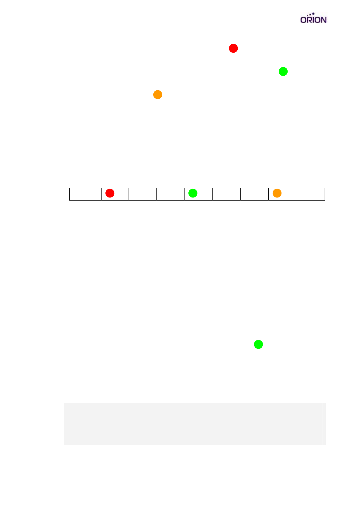
IX. Running in Normal Mode
1. When OBDtrac runs on normal mode. PWR LED should be flashing
periodically. This means OBDtrac is in POWER ON status and the
GPS system is functioning. About 30 seconds later, GSM LED will
start flashing and then stays ON const antly, this means GPRS session
is now online. The GPS LED will also start to flash, showing the
tracker is searching for a GPS signal. It will stays ON when GPS signal
is fixed.
Note: The default Primary Gateway Server IP in the tracker is
220.128.135.215 that is one of ORION Testing Servers with a
tcpserver.exe running on it. By connecting to ORION Testing Sever
allows you to verify the tracker and the SIM card very quickly.
PWR
Flash
GSM
ON
GPS
ON
Note: Before connecting OBDtrac to your server. A Gateway Server
which runs the tcpserver.exe with a public IP address must be ready.
The tcpserver.exe is basically a TCP socket listener that builds the
socket sessions with multiple trackers via TCP/IP over GPRS and the
Internet. To verify that your Gateway Server is working, you may use
the “AVL Simulator” program to send simulated SYNC packets and
GPS data to the Gateway Server.
2. After a few minutes, if the GPRS settings are correct with a working
SIM card that has GPRS service enabled, OBDtrac will build a
communication session with the Gateway Server over GPRS and
starts to send GPS positions to the Gateway Server.
Note: If the Gateway Server is not ready, the GSM LED will keep
flashing.
3. If the OBDtrac and the Gateway Server are both working well. The
following messages will be displayed on the Hyper Terminal window.
- Version : 0.12
- Serial Number : EH1234567890
- Unit ID : 1000000001
- IMEI : 123456789012345
© 2007 ORION Technology LTD. All rights reserved. 27/40
Page 28
GPRS Tracking Report Syntax :
Real time GPS Data Report format:
$RGTK,[UnitID],[UTCTime],[A|V],[Longitude],[E|W],[Latitude],[N|S],[Satellite
Numbers],[GSM Signal],[Angle],[Speed],[Mileage],[AI1],[AI2],[DI],[DO],[RTCTime]&
Resent format: (When the GPRS is recovered, the tracker will resend all GPS data logs
to the Gateway Server automatically.)
$LGTK,[UnitID],[UTCTime],[A|V],[Longitude],[E|W],[Latitude],[N|S],[Satellite
Numbers],[GSM Signal],[Angle],[Speed],[Mileage],[AI1],[AI2],[DI],[DO],[RTCTime]&
Field Description
Event Type Event Type
UnitID UnitID
UTC Time GPS Date and Time.
The format is DDMMYYHHmmss
A|V GPS Data is Valid or Invalid. “A” = valid, “V” = invalid.
Longitude GPS Longitude
E/W “E”= East, “W” = West.
Latitude GPS Latitude
N/S “N” = North, “S” =South
Satellite Numbers Satellite Numbers acquired. The maximum satellite number is 12.
Normally the SiRF Star III can receive about 6~8 satellites if the
GPS antenna is in the open sky.
GSM Signal GSM Signal strength, From 0 to 31, Unknown: 99 or other numbers
The maximum GSM signal is 31. Normally it should be more than
20. If it is less than 20, it means poor GSM reception of OBDtrac in
that particular area. T ry to adjust the location of GSM Antenna for a
stronger GSM signal
Angle GPS Angle, unit = degree
Speed GPS Speed, unit = knot
Mileage Accumulated Mileage of the tracker. It is calculated by GPS data.
Unit = ‘mile’. Maximum value: 999999.99
© 2007 ORION Technology LTD. All rights reserved. 28/40
Page 29

RTC Time Device RTC (Real Time Clock) Date and Time.
The format is YYMMDDHHmmss
4. If the AVL Manager.exe and Gateway Server are working well, it
shows the SYNC packet and GPS data on the Demo window too. You
can compare them to those showing on the Hyper Terminal window.
5. If OBDtrac cannot connect to the Gateway Server and send GPS data,
please check first if all the configurations are correct. Otherwise
please copy the whole messages from the Hyper Terminal window and
send an email to [email protected]
support.
for further technical
© 2007 ORION Technology LTD. All rights reserved. 29/40
Page 30
3. Update firmware by Hyper Terminal
1. ET250 supports firmware upgrade by Hyper Terminal after firmware
version 970603. ORION releases the .img file (Application code only)
to allow our customers to update the firmware by Hyper Terminal or by
GPRS.
2. It takes only 3 steps to update the firmware by Hyper Terminal, and the
task can be done under the regular ‘Debug Mode’ via RS-232
connection to PC.
3. Please follow the instructions below to update firmware of the tracker.
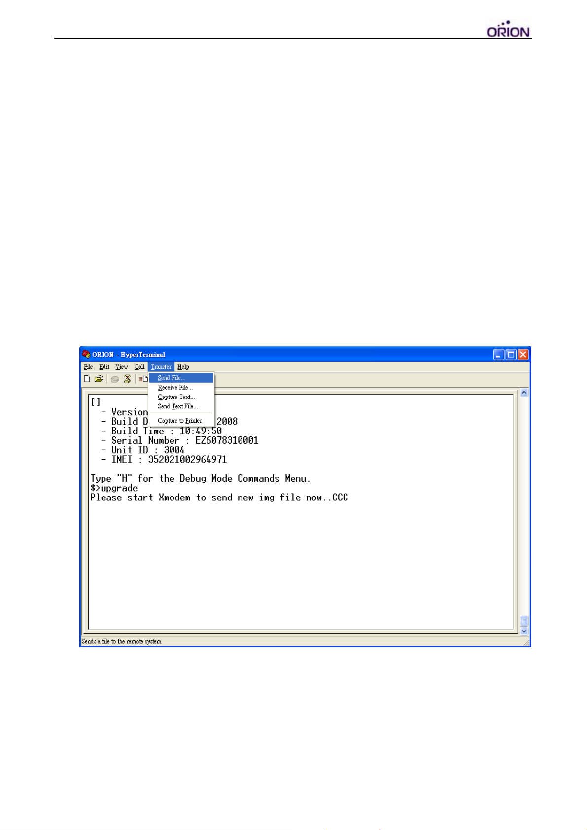
Step 1: Power ON the tracker and type ‘Esc’ within 3 seconds to enter
‘Debug Mode’. Type ‘UPGRADE’ or ‘upgrade’, then click the menu bar to
open ‘Send File’ window. Select the new .img file and ‘1K Xmodem’
protocol to send the .img file.
© 2007 ORION Technology LTD. All rights reserved. 30/40
Page 31
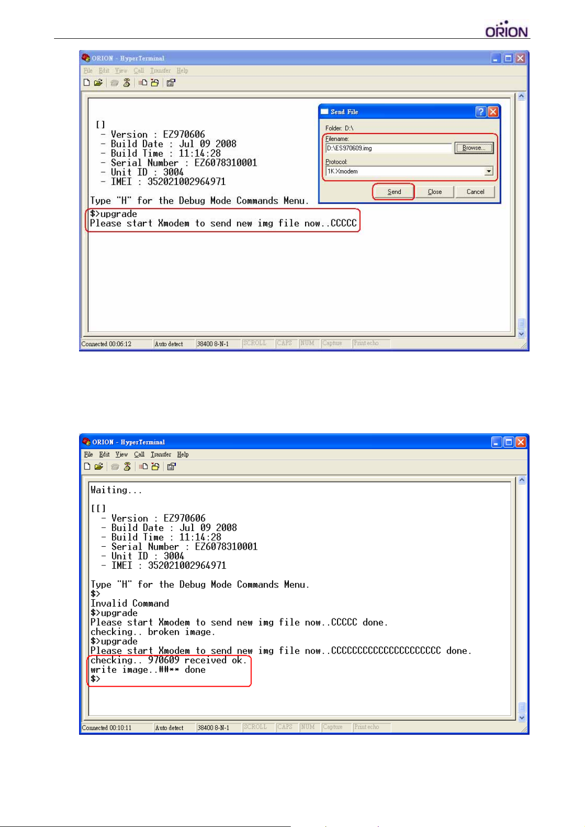
Step 2: Wait until the file has been uploaded, the following messages
should show up to indicate the new firmware is received successfully by
the tracker.
© 2007 ORION Technology LTD. All rights reserved. 31/40
Page 32

Step 3: Type ‘reboot’ command to reboot the tracker. Enter the debug
mode again to check the firmware version. If it is correct, then the firmware
update is complete.
4. Update firmware over the air (OTA) by GPRS
1. ORION OBDtrac supports over the air upgrade after firmware version
970708. Also the firmware replies each SMS protocol command to
sender’s phone number. It becomes much easier for the tracker
maintenance.
2. ORION releases the .img file (Application code only) to allow our
customers to update the firmware over the air by GPRS. The system
administrator uploads the .img file to a web server, then sends a
protocol command to the tracker by SMS or GPRS. Afterward the
tracker will perform the firmware download and update by itself.
3. It takes only 3 steps to update the firmware over the air by GPRS.
Please follow the instructions below to update the firmware of the
tracker.
Step 1: Put the new firmware on a web server and come out the URL.
http://211.79.38.93/970709.img
or http://211.79.38.93:8080/970709.img ). Or
(Ex.
you may use the URL provided by ORION. Please note that you may have
to rename the .img to .zip or other file name in order to pass the firewall.
(Ex. http://211.79.38.93/970709.zip
). Note that only http is supported, not
ftp.
Step 2: Send the protocol command $ActUpgradeFW, [Command
S/N],[Password],[URL]& by SMS or GPRS to the tracker to initiate the
firmware update process.
Step 3: Verify if the firmware update is successful by its return message.
Here are 4 cases of return messages.
1. When the tracker receives the command without problem, it will reply
the following acknowledgement first.
$ActUpgradeFW,[Command S/N],OK,[RTC Time]&
2. If the firmware download is in progress or parameters error, it replies:
$ActUpgradeFW,[Command S/N],Param,[RTC Time]&
© 2007 ORION Technology LTD. All rights reserved. 32/40
Page 33

3. If the firmware download fails, it replies the following message. In this
case, you have to send $ActUpgradeFW again to do it over.
$ActUpgradeFW,[Command S/N],FAIL,[RTC Time]&
(Note: Weak GSM signal or broken image file may cause download
problems. We recommend you to test and verify the firmware update
process before mass deployment.)
4. If the firmware update is successful, it replies the following information
after booting by the new firmware. All configuration will remain the same
and will not be affected by the new firmware.
$ActUpgradeFW,[Command S/N],DONE,<UnitID>,<IMEI>,<IMSI>,<HW
VER>,<FW VER>,<RTC>&
© 2007 ORION Technology LTD. All rights reserved. 33/40
Page 34
5. OBDtrac Dongle troubleshooting guideline
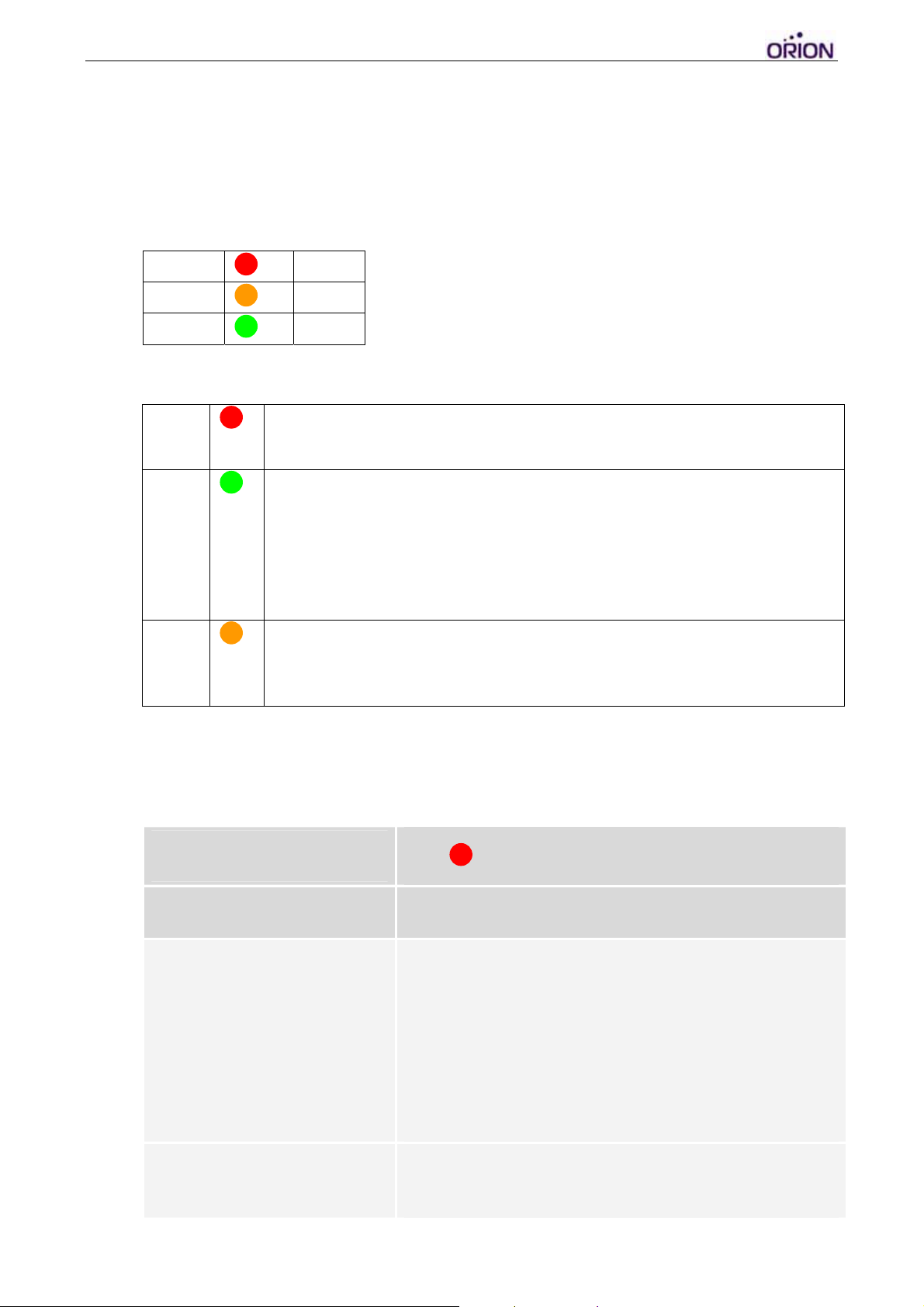
1. When the OBDtrac Basic is installed and running in the vehicle. The
LED indicators have to perform as indicated in the following table.
Otherwise, it will require further inspections.
PWR
GPS
GSM
Flash
ON
ON
2. LED indicators
PWR
GSM
GPS
OFF: Power OFF
Flash: Power ON
OFF: GSM module OFF or Error
Flash: No SIM Card, Searching networks (0.25sec ON 0.5sec
OFF)
Flash: GSM registered (0.5sec ON 0.5sec OFF)
Flash: GPRS connecting (0.25sec ON 0.25sec OFF)
ON: Socket session online (connect to Gateway Server)
OFF: GPS module OFF or Error
Flash: Searching GPS signal
ON: GPS fixed
3. Troubleshooting of the GPS tracker:
I. The tracker is disconnected to the server and the PWR LED is
OFF or DIM.
Problem
Cause Solution
No power supply to the tracker 1. Check the connector of the power cable connecting
The power cable is faulty 1. Check if there is any damage of the cable and the
PWR LED is OFF or DIM
to the tracker correctly and securely. If not,
reconnect the power cable to the tracker and secure
it.
2. Use a voltmeter to check if the power supply from
the vehicle is between 9V to 30V.
3. Check the black wire (Ground) connecting to the
ground of the vehicle power circuit correctly.
surge protector. If yes, the power cable needs to be
replaced.
© 2007 ORION Technology LTD. All rights reserved. 34/40
Page 35

2. Check if there is vehicle power supplying to the
power cable correctly, then use the voltmeter to
check if there is correct power output more than 9V
from the surge protector.
3. The surge protector has internal resettable fuse that
will recover by itself couple minutes later when
overloading. If there is no constant power supply
from it, then the power cable may be damaged and
needs to be replaced.
The tracker is faulty 1. If there is correct power output from the power cable
and the power LED is still OFF, maybe the tracker is
faulty and needs to be replaced for further
inspection.
2. When the tracker is back to the office. Use the AC
adapter to supply power to the tracker and check the
power LED again.
II. The tracker is disconnected to the server and the GSM LED is not
constant ON.
Problem
Cause Solution
Poor GSM signal reception 1. Use the cell phone to check if the GSM signal is
GSM LED is constant OFF or flashing
weak there. If yes, move the vehicle for better GSM
reception and check again.
2. Check the GSM antenna connects to the tracker
correctly and securely. Sometimes it is switched with
the GPS antenna connection intentionally.
3. Check if the GSM antenna is installed at a proper
place to have a clear view of the sky.
4. Check if the GSM antenna cable is twisted or
damaged. If yes, the GSM antenna needs to be
replaced.
5. Change the GSM antenna and check again.
Poor internet connectivity 1. The GSM network is busy. The tracker can’t register
to the GSM network. Press the reset button in the
rear panel of the tracker. Wait for 5 minutes and
check again.
2. The GPRS connection is not available or the GSM
signal is too weak to open a GPRS connection.
Press the reset button in the rear panel of the
tracker. Wait for 5 minutes and check again.
3. The SIM card is invalid or blocked. Change a valid
SIM card (from the same provider) and check again.
© 2007 ORION Technology LTD. All rights reserved. 35/40
Page 36

The Gateway Server is down 1. The Gateway Server is down or the internet
connection is blocked. Thus, the tracker can’t build
up a GPRS connection with the Gateway Server.
Check with the MIS engineer.
2. The Gateway Server shuts off the socket connection
or hang the connection due to poor socket
management. Check with the MIS engineer.
The tracker firmware is faulty 1. Press the reset button in the rear panel of the
tracker. Wait for 5 minutes and check again.
2. When the tracker is back to the office. Check if the
tracker remains all GPRS parameters and server
settings correctly.
The tracker hardware is faulty 1. If the GSM LED remains constant OFF after
pressing the reset button, it means the tracker may
be damaged and needs to be replaced.
2. When the tracker is back to the office. Use the AC
adapter to supply power to the tracker and check the
tracker by Hyper Terminal for further information.
III. The tracker connects to the server with invalid GPS all the time
and the GPS LED is not constant ON.
Problem
Cause Solution
Poor GPS signal reception 1. Check the GPS antenna connects to the tracker
GPS LED is constant OFF or flashing
correctly and securely. Sometimes it is switched with
the GSM antenna connection intentionally.
2. Check if the GPS antenna is installed at a proper
place to have a clear view of the sky.
3. Check if the GPS antenna cable is twisted or
damaged. If yes, the GPS antenna needs to be
replaced.
4. Change the GPS antenna and check again.
The tracker firmware is faulty 1. Press the reset button in the rear panel of the
tracker. Wait for 5 minutes and check again.
2. When the tracker is back to the office. Check the
tracker by Hyper Terminal for further information.
The tracker hardware is faulty 1. If the GPS LED remains constant OFF or keeps
flashing after pressing the reset button, it means the
tracker may be damaged and needs to be replaced.
© 2007 ORION Technology LTD. All rights reserved. 36/40
Page 37

2. When the tracker is back to the office. Use the AC
adapter to supply power to the tracker and check the
tracker by Hyper Terminal for further information.
© 2007 ORION Technology LTD. All rights reserved. 37/40
Page 38

6. OBDtrac Dongle Wiring Diagram
© 2007 ORION Technology LTD. All rights reserved. 38/40
Page 39

IC:
This Class [*] digital apparatus complies with Canadian ICES-003.
Cet appareil numérique de la classe [*] est conforme à la norme NMB-003 du
Canada.
Exposure of humans to RF fields (RSS-102)
The computers employ low gain integral antennas that do not emit RF field in
excess of Health Canada limits for the general population; consult Safety Code 6,
obtainable from Health Canada's Web site at http://www.hc-sc.gc.ca/
The radiated energy from the antennas connected to the wireless adapters
conforms to the IC limit of the RF exposure requirement regarding IC RSS-102,
Issue 4 clause 4.1.
Conformité des appareils de radiocommunication aux limites
d'exposition humaine aux radiofréquences (CNR-102)
L'ordinateur utilise des antennes intégrales à faible gain qui n'émettent pas un
champ électromagnétique supérieur aux normes imposées par Santé Canada
pour la population. Consultez le Code de sécurité 6 sur le site Internet de Santé
Canada à l'adresse suivante : http://www.hc-sc.gc.ca/
L'énergie émise par les antennes reliées aux cartes sans fil respecte la limite
d'exposition aux radiofréquences telle que définie par Industrie Canada dans la
clause 4.1 du document CNR-102, version 4.
Caution: Exposure to Radio Frequency Radiation.
To comply with RSS 102 RF exposure compliance requirements, a separation distance of at least 20 cm must be maintained between
the antenna of this device and all persons.
Pour se conformer aux exigences de conformité CNR 102 RF exposition, une distance de séparation d'au moins 20 cm doit être
maintenue entre l'antenne de cet appareil et toutes les personnes
FCC
Federal Communications Commission (FCC) Statement
15.21
You are cautioned that changes or modifications not expressly
approved by the part responsible for compliance could void the user’s
authority to operate the equipment.
15.105(b)
This equipment has been tested and found to comply with the limits for a
Class B
digital device, pursuant to part 15 of the FCC rules. These limits are
designed to provide reasonable protection against harmful interference
in a residential installation. This equipment generates, uses and can
radiate radio frequency energy and, if not installed and used in
accordance with the instructions, may cause harmful interference to
radio communications. However, there is no guarantee that interference
will not occur in a particular installation. If this equipment does cause
harmful interference to radio or television reception, which can be
determined by turning the equipment off and on, the user is encouraged
to try to correct the interference by one or more of the following
measures:
-Reorient or relocate the receiving antenna.
-Increase the separation between the equipment and receiver.
-Connect the equipment into an outlet on a circuit different from that to
which the receiver is connected.
© 2007 ORION Technology LTD. All rights reserved. 39/40
Page 40

-Consult the dealer or an experienced radio/TV technician for help.
FCC RF Radiation Exposure Statement:
This equipment complies with FCC RF radiation exposure limits set forth
for an uncontrolled environment. This equipment should be installed
and operated with a minimum distance of 20 centimeters between the
radiator and your body.
CE
CE Marking
This device has been tested to and conforms to the regulatory
requirements of the European Union and has attained CE Marking. The
CE Mark is a conformity marking consisting of the letters “CE”. The CE
Mark applies to products regulated by certain European health, safety
and environmental protection legislation. The CE Mark is obligatory for
products it applies to: the manufacturer affixes the marking in order to
be allowed to sell his product in the European market.
This product conforms to the essential requirements of the R&TTE
directive 1999/5/EC in order to attain CE Marking. A notified body has
determined that this device has properly demonstrated that the
requirements of the directive have been met and has issued a favorable
certificate of expert opinion. As such the device will bear the notified
body number 0560 after the CE mark.
The CE Marking is not a quality mark. Foremost, it refers to the safety
rather than to the quality of a product. Secondly, CE Marking is
mandatory for the product it applies to, whereas most quality markings
are voluntary.
Marking: The product shall bear the CE mark, the notified body
number(s) as depicted to the right. CE0560.
Tel: +886-2-2521-2610
http://
Email:
© 2007 ORION Technology LTD. All rights reserved. 40/40
www.oriontech.com.tw
 Loading...