

Page 1

LDP-135 -
340 LCD / 235
- 240 LED series
Bedienungsanleitung /
operation manual
Voltmeter - Module / Modules
Page 2

1. Allgemeines
Bei diesen LCD- bzw. LED-Voltmeter-Modulen handelt es sich
um 3 ½ - stellige Module, die für den Einsatz in Voltmetern
und Amperemetern geeignet sind.
Sie erlauben die Messung von Gleichspannungen bis max.
500 V, abhängig von der Beschaltung von Ra und Rb sowie
die Messung von Gleichströmen von 0,2 mA bis max. 2 A je
nach Bemessung des verwendeten Shunts bei einer max.
Spannung im Messkreis von 35 V DC.
Ein anderer Einsatz der Module als die hier geschilderten
Möglichkeiten, ist nicht zulässig.
Die LCD-Module LDP-140 LCD und LDP-340 LCD verfügen
außerdem über eine Hintergrundbeleuchtung.
2. Sicherheitshinweise
Vor Inbetriebnahme des Moduls, Sicherheitshinweise und
Bedienungsanleitung unbedingt lesen und beachten!
Schäden, die durch Nichtbeachtung dieser Hinweise
entstehen, sind von Ansprüchen jeglicher Art ausgeschlossen.
* Diese Module dürfen nicht in Installationen der Über-
spannungskategorie II nach IEC 664 verwendet werden. Die
Module sind nicht gegen Lichtbogenexplosion geschützt !
-1-
Page 3

* Bei der Messung, und entsprechender Beschaltung des
Moduls, von Spannungen über 30 V
DC muss das Modul und das System, in dem das Modul
integriert ist, den relevanten Abschnitten der Vorschrift EN-
= 42 Vss oder 60 V
eff
61010-1 (Sicherheitsanforderungen an elektrische Geräte
zur Messung, Steuerung und für Laboratorien =
Niederspannungsrichtlinie) entsprechen.
* Bei gewerblichen Einrichtungen unbedingt die Unfall-
verhütungsvorschriften des Verbandes der gewerblichen
Berufsgenossenschaften für elektrische Anlagen und
Betriebsmittel beachten!
* Vorsicht beim Umgang mit Spannungen über 25 V AC bzw.
35 V DC. Auch bei diesen Spannungen besteht im Falle der
Berührung eines elektrischen Leiters Verletzungsgefahr
durch elektrischen Schlag.
* Vor der Änderung des Messbereiches (andere Bestückung
von Ra und Rb) sind die Anschlusskabel vom Messobjekt zu
entfernen.
* Messgeräte gehören nicht in Kinderhände !
3. Technische Daten
max. EingangsSpannung
(Grundgeräte;
Ra = offen,
Rb = gebrückt) 199,9 mV DC
max. Anzeige 1999 (3 ½ - stellig) mit automatischer
Anzeigeart LCD- bzw. LED-Anzeige
Polaritätsanzeige
Messprinzip Doppelflanken A/D-Wandler
-2-
Page 4

Segmenthöhe LDP-135 LCD: 13 mm
LDP-140 LCD: 13 mm
LDP-235 LED: 14 mm rot
LDP-240 LED: 14 mm grün
LDP-335 LCD: 8 mm
LDP-340 LCD: 8 mm
Überbereichsanzeige “1” erscheint im Anzeigefeld
Messfolge 2...3 x pro Sekunde
Eingangswiderstand > 100 MΩ
Genauigkeit ± 0,5 % (bei 23° C ± 5° C und
einer Luftfeuchtigkeit von < 80%)
Verlustleistung ca. 1 mA DC (LDP-135/335LCD)
ca. 30 mA DC (LDP-340 LCD)
ca. 48 mA DC (LDP-140 LCD)
ca. 50-60 mA DC (LDP-235/240LED)
Dezimalstelle mit Kurzschlussstecker wählbar
Befestigung Klipp-Montage
Frontplattenausschnitt LDP-135/140:
54,5 mm Breite x 38,0 mm Höhe
LDP-335/340:
43,5 mm Breite x 19,5 mm Höhe
LDP-235/240:
Betriebsspannung 9 V DC (LCD) 9...12 V DC (LED)
69,5 mm Breite x 46,5 mm Höhe
-3-
Page 5

Abmessungen LDP-135/140: 68,5 x 40,5 x 18 mm
LDP-335/340: 47 x 20 x 16 mm
4. Betrieb
Vor der Inbetriebnahme muss auf eine ausreichende Isolation
des Moduls und die Einhaltung der Luft- und Kriechstrecken
gem. VDE 0411 bzw. VDE 410 und EN 61010-1 gewährleistet
sein.
Wichtig! Bitte verwenden Sie für Lötarbeiten nur Feinlötkolben
bis 20 W.
Am Versorgungseingang eine Spannung von
- 9 V DC (LDP-135 / 140 / 335 / 340 LCD)
- 9 ... 12 V DC (LDP-235 / 240 LED)
anschließen (9 V Batterie) und unbedingt die Polarität
beachten.
ACHTUNG!
Eine gleichzeitige Versorgung des Messgerätes und Messung
der Versorgungsspannung ist mit diesem Modul nicht möglich.
Der Betrieb mehrerer Messgeräte über die gleiche
Versorgungsspannung ist nicht möglich (ein Messgerät = eine
Versorgungsspannung, z. B. 9 V-Batterie)
4.1. Veränderung der Spannungsteiler
a) Bei Bedarf können die in der Tabelle angegebenen
Spannungsteiler und Kurzschlussstecker eingefügt bzw.
LDP-235/240: 83 x 49,5 x 22 mm
-4-
Page 6
umgesteckt werden. Die Widerstände sind nicht im Lieferumfang enthalten.
ACHTUNG! Vor Veränderung der Spannungsteiler (Ra und
Rb), Modul unbedingt vom Mess- und Versorgungskreis
(Batterie) trennen.
LDP-135 / 140 LCD:
Max.
Mess-
Erforderlicher
Spannungsteiler
Kommastelle
spannung
200 mV Ra: offen (Lieferzustand)
2 V
20 V
200 V
500 V
LDP 235 / 240 LED:
Max.
Mess-
Rb: 0 Ω
Ra: 1 MΩ / Rb: 9 MΩ
Ra: 100 kΩ / Rb: 9,9 MΩ
Ra: 10 kΩ / Rb: 9,99 MΩ
Ra: 1 kΩ / Rb: 9,999 MΩ
Erforderlicher
Spannungsteiler
P3 kurzschließen
P1 kurzschließen
P2 kurzschließen
P3 kurzschließen
Kommastelle
spannung
200 mV
Ra: 0 Ω (Lieferzustand)
P3 kurzschließen
Rb: offen
2 V
20 V
200 V
500 V
Ra: 9 MΩ / Rb: 1 MΩ
Ra: 9,9 MΩ / Rb: 100 kΩ
Ra: 9,99 MΩ / Rb: 10 kΩ
Ra: 9,999 MΩ / Rb: 1 kΩ
P1 kurzschließen
P2 kurzschließen
P3 kurzschließen
-5-
Page 7

LDP 335 / 340 LCD:
Max.
Mess-
spannung
200 mV
2 V
20 V
200 V
500 V
Die Widerstände Ra und Rb sind ½ Watt, 0,5 % MetallfilmWiderstände.
b) Externe DC-Spannungsquelle an das Modul anschließen.
c) Genauigkeit für alle Bereiche (ausgenommen den
200 mV-Bereich) bei einer Kalibrierspannung von 50%
(z. B. von 100 V im 200 V-Bereich) einstellen und mit
Potentiometer auf gleiche Anzeige abgleichen.
d) Zu messende Spannung an die Eingänge Vin und GND
anlegen. Nur DC-Spannungen an die Eingänge anlegen.
4.2. Gleichstrommessung
Für Gleichstrommessungen, Messeingang gemäß der
folgenden Tabelle beschalten.
Erforderlicher
Spannungsteiler
Ra: 0 Ω (Lieferzustand)
Rb: offen
Ra: 9 MΩ / Rb: 1 MΩ
Ra: 9,9 MΩ / Rb: 100 kΩ
Ra: 9,99 MΩ / Rb: 10 kΩ
Ra: 9,999 MΩ / Rb: 1 kΩ
-6-
Kommastelle
P3 kurzschließen
P1 kurzschließen
P2 kurzschließen
P3 kurzschließen
Page 8

Shunt ( = NebenMessbereich Kommastelle widerstand)
200 µA P 3 kurzschl. 1 kΩ
2 mA P 1 kurzschl. 100 Ω
20 mA P 2 kurzschl. 10 Ω
200 mA P 3 kurzschl. 1 Ω
2000 mA 0,1 Ω
Achtung! Die max. Spannung im Messkreis darf 35 V DC auf
keinen Fall überschreiten. Der Messeingang für Strom/
Spannung ist nicht abgesichert.
-7-
Page 9

4.3. Schaltungsvorschläge
5. Anschlussplan
LDP-135 / LDP-140 Rückansicht:
-9-
Page 10

LDP-235 / LDP-240 Rückansicht:
LDP-335 / LDP-340 LCD Rückansicht:
zum Setzten des Dezimalpunktes
-9-
Page 11

Alle Rechte, auch die der Übersetzung, des Nachdruckes und
der Vervielfältigung dieser Anleitung oder Teilen daraus,
vorbehalten. Reproduktionen jeder Art (Fotokopie, Mikrofilm
oder ein anderes Verfahren) nur mit schriftlicher Genehmigung
des Herausgebers gestattet.
Letzter Stand bei Drucklegung. Technische Änderungen des
Gerätes, welche dem Fortschritt dienen, vorbehalten.
Hiermit bestätigen wir, dass das Gerät die in unseren
Unterlagen genannten Spezifikationen erfüllt und werkseitig
kalibriert geliefert wird.
Eine Wiederholung der Kalibrierung nach Ablauf von 1 Jahr
wird empfohlen.
©PeakTech® 04/2012/Ho/Th.
-10-
Page 12

1. General
These LCD-/LED-voltmeter modules are 3 ½ digit modules for
application in Voltmeter and Amperemeter.
They are suitable for measuring DC voltage up to max. 500 V,
depending of the wiring of Ra and Rb. You can also measure
DC current of 0.2 mA up to max. 2 A, depending of the rating
of the used shunts at a max. voltage of the measuring circuit of
35 V DC.
Another application of the modules instead of the described is
not allowed.
The models LDP-340 and LDP-140 are additionally provided
with a backlight.
2. Safety regulations
Before connecting the modules, read and take note of the
following safety regulations and instruction manual.
Damages resulting from failure to observe these safety
precautions are exempt from any legal claims whatever.
* During the measurement of voltages over 30 V
(= 42 Vpp)or 60 V DC with respective wiring of the module
rms
take care that the circuit, in which you use the module
follows the relevant safety regulations of the EN-61010-1.
* Do not use these modules in installation with overvoltage
category III according IEC 664. The modules are not
protected against arcing.
-11-
Page 13

* Use caution when working above 25 V AC or 35 V DC.
Even such voltage poses a shock hazard.
* Before you change the measuring range (another wiring of
Ra and Rb) remove the probe tips from the circuit.
* Measuring instruments don’t belong to children hands
3. Technical Data
max. input voltage
(basic instrument,
Ra = open;
Rb = shorted) 199,9 mV DC
max. display 1999 (3 ½-digit) with automatic
polarity indication
Display LCD i. e. LED elements
Measuring principle dual slope A/D converter
Cipher height LDP-135/140: 13 mm
LDP-335/340: 8 mm
LDP-235/240: 14 mm
Overflow indication “1” is displayed
Sampling rate 2...3 times per second
Input impedance > 100 MΩ
Accuracy ± 0,5 % (at 23° C ± 5° C and a
relative humidity of < 80 %)
-12-
Page 14

Power dissipation 1 mA DC (LDP-135/335)
30 mA DC (LDP-340)
48 mA DC (LDP-140)
50...60 mA DC (LDP-235/240)
Decimal point selectable with jumper
Mounting holes LDP-135/140:
54,5 mm (W) x 38,8 (H) mm
LDP-335/340:
43,5 mm (W) x 19,5 (H) mm
LDP-235/240:
69,5 mm (W) x 46,5 (H) mm
Supply voltage 9 V DC (LCD) 9...12 V DC (LED)
Dimensions:
LDP-135/140: 68,5 x 40,5 x 18 mm
LDP-335/340: 47 x 20 x 16 mm
LDP-235/240: 83 x 49,5 x 22 mm
4. Operation
Before operating take care that the module is enough isolated
and the air section and leakage path according VDE 0411 i. e.
VDE 0410 and EN 61010-1 is guaranteed.
Important!
Please use only soldering irons with max 20 W!
Connect a voltage of
- 9 V DC (LDP-135 / 140 / 335 / 340 LCD)
-13-
Page 15

- 9 … 12 V DC (LDP-235 / 240 LED) to the supply input (9 V
battery).
Please consider the polarity.
Caution!
A simultaneously supply of the module and measuring of the
supply voltage is not possible.
Operation of several modules with same power supply is not
possible (one module = one power supply, i. e. 9 V battery).
4.1. Changing the voltage divider
a) The voltage in the following chart can be added and the
jumper plug accordingly displayed if required (resistors
are optional components).
LDP-135 / 140 LCD:
Max.
measuring
voltage
200 mV Ra: open (factory setting)
2 V
20 V
200 V
500 V
Required voltage divider Decimal point
RB: 0 Ω
Ra: 1 MΩ
Rb: 9 MΩ
Ra: 100 kΩ
Rb: 9,9 MΩ
Ra: 10 kΩ
Rb: 9,99 MΩ
Ra: 1 kΩ
Rb: 9,999 MΩ
-14-
Short P3
Short P1
Short P2
Short P3
Page 16

LDP 235 / 240 LED:
Max.
Required voltage divider Decimal point
measuring
voltage
200 mV
Ra: 0 Ω (factory setting)
Rb: open
2 V
Ra: 9 MΩ
Rb: 1 MΩ
20 V
Ra: 9,9 MΩ
Rb: 100 kΩ
200 V
Ra: 9,99 MΩ
Rb: 10 kΩ
500 V
Ra: 9,999 MΩ
Rb: 1 kΩ
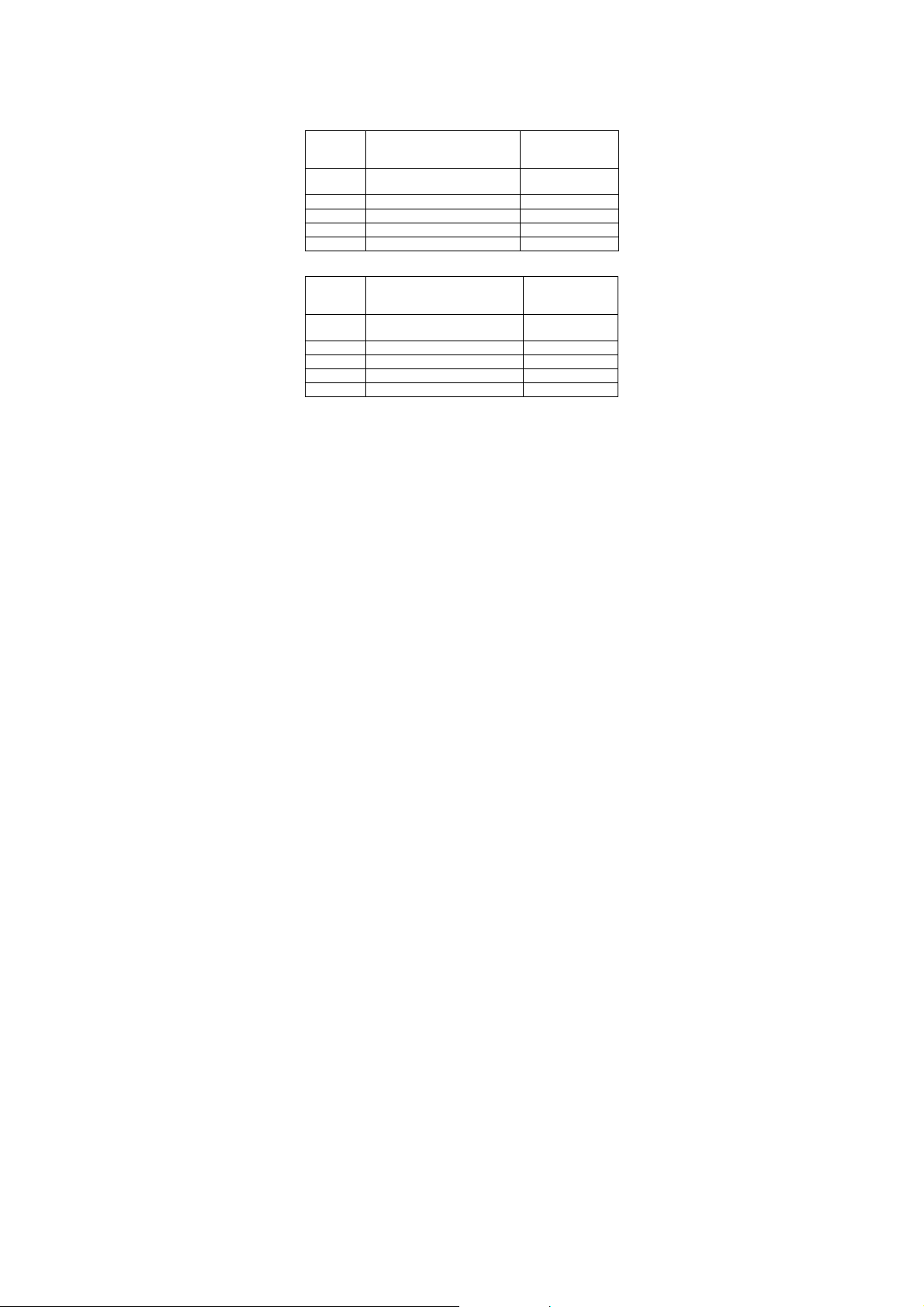
LDP 335 / 340 LCD:
Max.
Required voltage divider Decimal point
measuring
voltage
200 mV
Ra: 0 Ω (factory setting)
Rb: open
2 V
Ra: 9 MΩ
Rb: 1 MΩ
20 V
Ra: 9,9 MΩ
Rb: 100 kΩ
200 V
Ra: 9,99 MΩ
Rb: 10 kΩ
500 V
Ra: 9,999 MΩ
Rb: 1 kΩ
Short P3
Short P1
Short P2
Short P3
Short P3
Short P1
Short P2
Short P3
-15-
Page 17

Resistors Ra and Rb are ½ Watt; 0,5 % metal-foil resistors.
b) Connect module to an external DC voltage source.
c) The accuracy on all ranges expect 200 mV range should
be adjusted with a calibrated voltage of 50% of the
selected range (i. e. 100 V for 200 V range). Adjust
potentiometer for equal reading of scale.
d) Connect the voltage to be measured to terminals VIN and
GND (4). Connect DC voltages to the input terminals only.
4.2. Measuring DC current
To measure DC current, wiring measuring input (4) as per
following table:
Range Decimal-point Shunt
200 µA Short P3 1 kΩ
2 mA Short P1 100 Ω
20 mA Short P2 10 Ω
200 mA Short P3 1 Ω
2000 mA 0,1 Ω
-16-
Page 18

Caution! The max. voltage should not exceed 35 V DC in the
circuit. The measuring input for current/voltage is not
protected.
4.3. Recommended circuit configurations
5. Connecting diagram
LDP-135 / LDP-140 Back-view:
-17-
Page 19

LDP-235 / LDP-240 Back-view:
LDP-335 / LDP-340 LCD Back-view:
for setting the decimal-point
for setting the decimal-point
-18-
Page 20

All rights, also for translation, reprinting and copy of this
manual or parts are reserved. Reproductions of all kinds
(photocopy, micro-film or other) only by written permission of
the publisher.
This manual is according the latest technical knowing.
Technical changing which are in the interest of progress
reserved.
We herewith confirm that the units are calibrated by the factory
according to the specifications as per the technical
specifications. We recommend to calibrate the unit again, after
1 year.
©PeakTech® 04/2012/Ho/Th
PeakTech Prüf- und Messtechnik GmbH
- Kornkamp 32 - DE-22926 Ahrensburg / Germany
+49-(0) 4102-42343/44
info@peaktech.de
+49-(0) 4102-434 16
www.peaktech.de
 Loading...