

Page 1

Page 2

i
Table of Contents
1. General Safety Requirements .................................................................................... 1
2. Safety Terms and Symbols ........................................................................................ 2
3. Quick Start ............................................................................................................... 3
3.1 Front/Rear Panel and User Interface .............................................................................. 3
3.1.1 Front Panel ...................................................................................................................................... 3
3.1.2 Rear Panel ....................................................................................................................................... 5
3.1.3 User Interface .................................................................................................................................. 5
Mode Icons ............................................................................................................................................................ 6
Status Icons ............................................................................................................................................................ 7
3.2 General Inspection ........................................................................................................ 7
3.3 Power-On Check ............................................................................................................ 7
3.4 Output Inspection ......................................................................................................... 8
3.4.1 Voltage Output Inspection .............................................................................................................. 8
3.4.2 Current Output Inspection .............................................................................................................. 8
4. Front Panel Operation .............................................................................................. 9
4.1 Turn On/Off the Channel Output ................................................................................... 9
4.2 Set the Output Voltage/Current ..................................................................................... 9
4.2.1 Set the Output Voltage .................................................................................................................... 9
4.2.2 Set the Output Current .................................................................................................................... 9
4.3 Over Voltage/Current Protection .................................................................................. 10
4.3.1 Set O.V.P ........................................................................................................................................ 10
4.3.2 Set O.C.P ........................................................................................................................................ 10
4.4 Programmable Output .................................................................................................. 11
4.4.1 Data View ...................................................................................................................................... 11
4.4.2 Output Set ..................................................................................................................................... 11
4.4.3 Data process .................................................................................................................................. 12
4.4.4 Turn On/Off Programmable Output .............................................................................................. 13
4.5 Save Settings/Auto Record ........................................................................................... 13
4.5.1 Save Settings ................................................................................................................................. 13
4.5.2 Auto Record ................................................................................................................................... 14
4.5.3 View Record .................................................................................................................................. 14
4.6 Output mode ............................................................................................................... 15
4.7 Utility Settings .............................................................................................................. 18
4.7.1 Language ....................................................................................................................................... 18
4.7.2 Brightness ...................................................................................................................................... 18
4.7.3 Beeper ........................................................................................................................................... 18
4.7.4 Clock .............................................................................................................................................. 18
Page 3

ii
4.8 System Info .................................................................................................................. 18
4.8.1 View System Information .............................................................................................................. 18
4.8.2 Set as Default................................................................................................................................. 18
4.8.3 Update ........................................................................................................................................... 19
4.9 Port Settings ................................................................................................................ 20
4.9.1 Serial port ...................................................................................................................................... 20
4.9.2 LAN Set .......................................................................................................................................... 20
4.9.3 LCD Test ......................................................................................................................................... 20
4.9.4 Key Test ......................................................................................................................................... 20
5. Tr oubleshooting ..................................................................................................... 21
6. Appendix ................................................................................................................ 21
6.1 Appendix A: Packaging ................................................................................................. 21
6.2 Appendix B: General Care and Cleaning......................................................................... 22
Page 4

1.General Safety Requirements
1
1. General Safety Requi rements
Before use, please read the following safety precautions to avoid any possible bodily
injury and to prevent this product or any other connected products from damage. To
avoid any contingent danger, ensure this product is only used within the ranges
specified.
Only a qualified person should perform internal maintenance.
To avoid Fire or Personal Injury:
Use Proper Power Cord. Use only the power cord supplied with the product and
certified to use in your country.
Product Grounded. This instrument is grounded through the power cord grounding
conductor. To avoid electric shock, the grounding conductor must be grounded. The
product must be grounded properly before any connection with its input or output
terminals.
Check all Terminal Ratings. To avoid fire or shock hazard, check all ratings and
markings on this product. Refer to the user manual for more information about
ratings before connecting to the instrument.
Do not operate without covers. Do not operate the instrument with covers or panels
removed.
Use the Proper Fuse. Use only the specified type and rating fuse for this instrument.
Avoid exposed circuit. Be careful when working on exposed circuitry to avoid risk of
electric shock or other injury.
Do not operate if any damage. If you suspect damage to the instrument, have it
inspected by qualified service personnel before further use.
Use your instrument in a well-ventilated area. Please keep well ventilated and
inspect the intake and fan regularly.
Do not operate in damp conditions. To avoid short circuiting to the interior of the
device or electric shock, please do not operate in a humid environment.
Do not operate in an explosive atmosphere. To avoid damages to the device or
personal injuries, it is important to operate the device away from an explosive
atmosphere.
Keep product surfaces clean and dry. To avoid the influence of dust or moisture in air,
please keep the surface of device clean and dry.
Page 5
2.Safety Terms and Symbols
2
2. Safety Terms and Symbols
Safety Terms
Terms in this manual (The following terms may appear in this manual):
Warning: Warning indicates conditions or practices that could result in injury or
loss of life.
Caution: Caution indicates the conditions or practices that could result in
damage to this product or other property.
Terms on the product. The following terms may appear on this product:
Danger: Indicates an immediate hazard or injury possibility.
Warning: Indicates a possible hazard or injury.
Caution: Indicates potential damage to the instrument or other property.
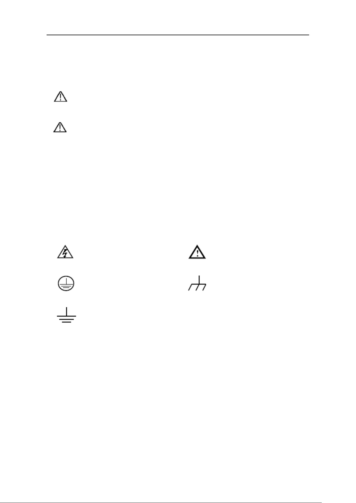
Safety Symbols
Symbols on the product. The following symbols may appear on the product:
Hazardous Voltage Refer to Manual
Protective Earth Terminal Chassis Ground
Public Ground
Page 6

3.Quick Start
3
①
⑬
⑦
⑥
⑤
②
⑨⑪
⑫
③
④
⑮
⑩
⑧
⑭
LCD
User interface display
Numeric keys area
Parameter input, includes the numeric keys, decimal point and
backspace ke y.
direction key
Enter key
Enter menu or confirm the parameter entered
Knob
Select menu or change the value, pressing it has the same
effect as pressing the enter key
Left and right
direction key
Set sub menu or move the cursor
CH3 control area
3. Quick Start
3.1 Front/Rear Panel and User Interface
3.1.1 Front Panel
①
②
Up and down
③
④
⑤
⑥
⑦
Figure 3-1 Front panel overview
Select sub menu
Volt CH3 key: Set the output voltage of CH3
Curr CH3 key: Set the output current of CH3
ON/OFF CH3 key: Enable/disable the output of CH3
Page 7

4
CH2 control area
Blue ON/OFF key: Enable/disable the output of CH2
terminals
MODE key
Switch between All Channel mode (CH1 & CH2 & CH3) and
Dual Channel Mode (CH1 & CH2).
terminals
CH3 output
terminals
Channel 3 output connectors
Power button
Turn on/off the instrument
CH1 control area
Orange ON/OFF key: Enable/disable the output of CH1
Function keys
more than 5 seconds, and release.
⑧
3.Quick Start
Blue Volt/CV key: Set the output voltage of CH2
Blue Curr/CC key: Set the output current of CH2
CH2 output
⑨
⑩
CH1 output
⑪
⑫
⑬
⑭
⑮
Channel 2 output connectors
Channel 1 output connectors
Orange Volt/CV key: Set the output voltage of CH1
Orange Curr/CC key: Set the output current of CH1
Utility key: Menu of output mode, utility, info, port settings.
Record key: Save settings, auto record, and view recording.
Program key: Programmable output.
KeyLock key: Press and hold this key for 5 seconds to lock
the panel keys. Unlock method: Press and hold the key for
Instructions for panel key indicator
ON/OFF key: The indicator will be lit after you turn on the channel.
Volt/CV key: The indicator will be lit when the channel is in Constant Voltage output
mode.
Curr/CC key: The indicator will be lit when the channel is in Constant Current output
mode.
Page 8
5
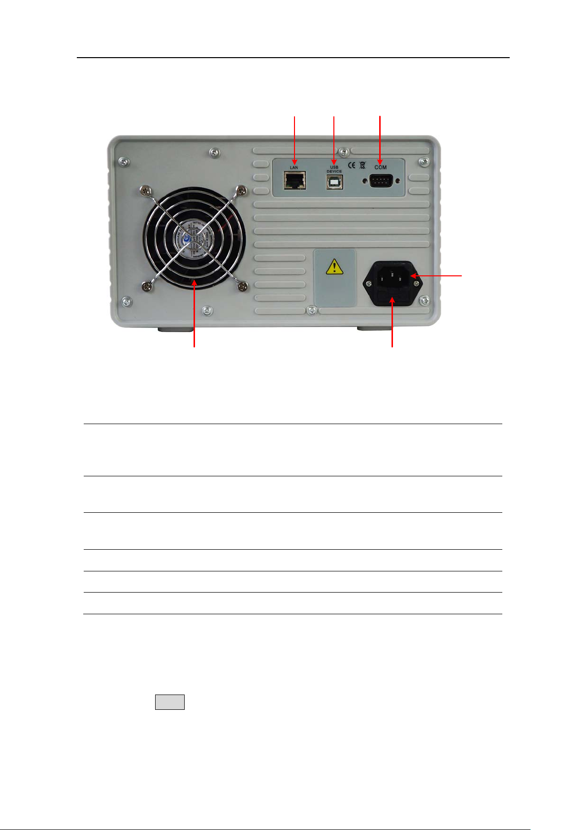
3.1.2 Rear Panel
①
②
③
⑤
④
⑥
Local Area
Connector
can be connected to the network for
USB Device
Connector
Connect as a "slave device" with an external USB device, such
as connect the instrument to a PC.
COM Connector
Connect the power supply with external equipment as serial
port.
Power socket
AC input connector
Fuse
Line fuse
Fan
Fan inlet
3.Quick Start
Figure 3-2 Rear panel overview
①
Network (LAN)
②
③
④
⑤
⑥
The power supply
remote control via this connector.
3.1.3 User Interface
When the output mode is in independent output, or channel tracking mode, there are
two display modes: All channel mode (CH1 & CH2 & CH3), Dual channel mode (CH1 &
CH2). Press the Mode panel key to switch between the modes.
All Channel Mode
Page 9

6
Channel 1
Channel 2
Set values of voltage
Actual current output
S
et values of O.V.P/O.C.P
CV:
Constant Voltage output
CC:
Constant Current outpu
t
Actual power output
Status icons
Actual voltage output
Set values of current
Mode icon
Figure 3-3 User interface in All channel mode
Set values of voltage
Actual current output
Set values of O.V.P/O.C.P
CV:
Constant Voltage output
CC:
Constant Current outpu
t
Actual power output
Status icons
Channel 1
Channel 2
Channel 3
Actual voltage output
Set values of current
Mode icon
Icons
Instruction
Dual Channel Mode
3.Quick Start
Mode Icons
Figure 3-4 User interface in Dual channel mode
All mode, display CH1, CH2 and CH3
Dual channel mode, display CH1 & CH2
The output mode is parallel tracking
The output mode is series tracking
Page 10
7
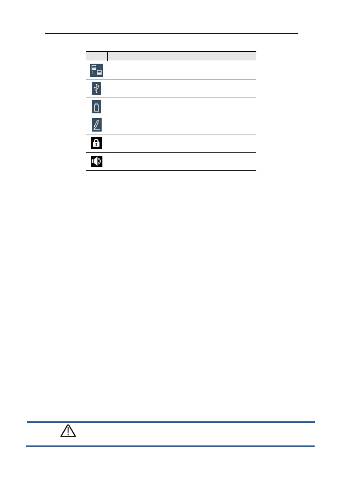
Status Icons
Icons
Instruction
Connected to the network via LAN connector
Connected as a slave device with PC
A USB device is connected
Recording the current output
The panel keys are locked
The beeper is turned on
3.2 General Inspection
3.Quick Start
When you receive your new power supply, it is recommended that you check the
instrument following these steps:
1. Check for transportation damage.
If it is found that the packaging carton or the foamed plastic protection cushion has
suffered serious damage, do not throw it away until the complete device and its
accessories have been electrically and mechanically checked.
2. Check the Accessories
The supplied accessories are described in the "Appendix A: " of this Manual. Please
ensure that all the listed accessories are present and undamaged, if any problems
are found please contact your distributor or OWON’s local office.
3. Check the Complete Instrument
If there is any physical damage, operational fault, or performance issue please
contact your distributor or OWON’s local office. If there is any transportation
damage to the instrument please ensure you keep the original packaging. Ideally you
should always keep the original packaging if the instrument must be returned for
repair.
3.3 Power-On Check
(1) Connect the instrument to the AC supply using the supplied power cord.
Warning:
To avoid electric shock, the instrument must be grounded properly.
Page 11

3.Quick Start
8
(2) Push the power button on the front panel, the keys will light and the screen will
show the boot screen.
3.4 Output Inspection
Output inspection is to ensure that the instrument can achieve its rated outputs and
properly respond to operation from the front panel. For the procedures below, it is
suggested that you read "Turn On/Off the Channel Output" on page 9 and "Set the Output
Voltage/Current" on page 9.
3.4.1 Voltage Output Inspection
The following steps verify basic voltage functions without load:
(1) When the instrument is under no load, select a channel and ensure the output
current setting for this channel is not at zero.
(2) Turn on the channel output, then ensure the channel is in Constant Voltage output
mode.
(3) Set some different voltage values on this channel; check if the actual voltage value
displayed is close to the set voltage value, and also that the actual current value
displayed is nearly to zero.
(4) Check that if the output voltage can be adjusted from zero to the maximum rating.
3.4.2 Current Output Inspection
The following steps check basic current functions with a short across the power supply's
output:
(1) Connect a short across (+) and (-) output terminals with an insulated test lead on this
channel. Use a wire size sufficient to handle the maximum current.
(2) Set the output voltage to the maximum rating on this channel.
(3) Turn on the channel output. Ensure the channel you used is in Constant Current
output mode.
(4) Set some different current values on this channel; check if the actual current value
displayed is close to the set current value, and to check if the actual voltage value
displayed is nearly zero.
(5) Check that if the output current can be adjusted from zero to the maximum rating.
(6) Turn off the channel output and remove the short circuit from the output terminals.
Page 12
4.Front Panel Operation
9
4. Front Panel Operation
4.1 Turn On/Off the Channel Output
Press the orange ON/OFF key to turn on/off the Channel 1 output.
Press the blue ON/OFF key to turn on/off the Channel 2 output.
Press the ON/OFF CH3 key to turn on/off the Channel 3 output.
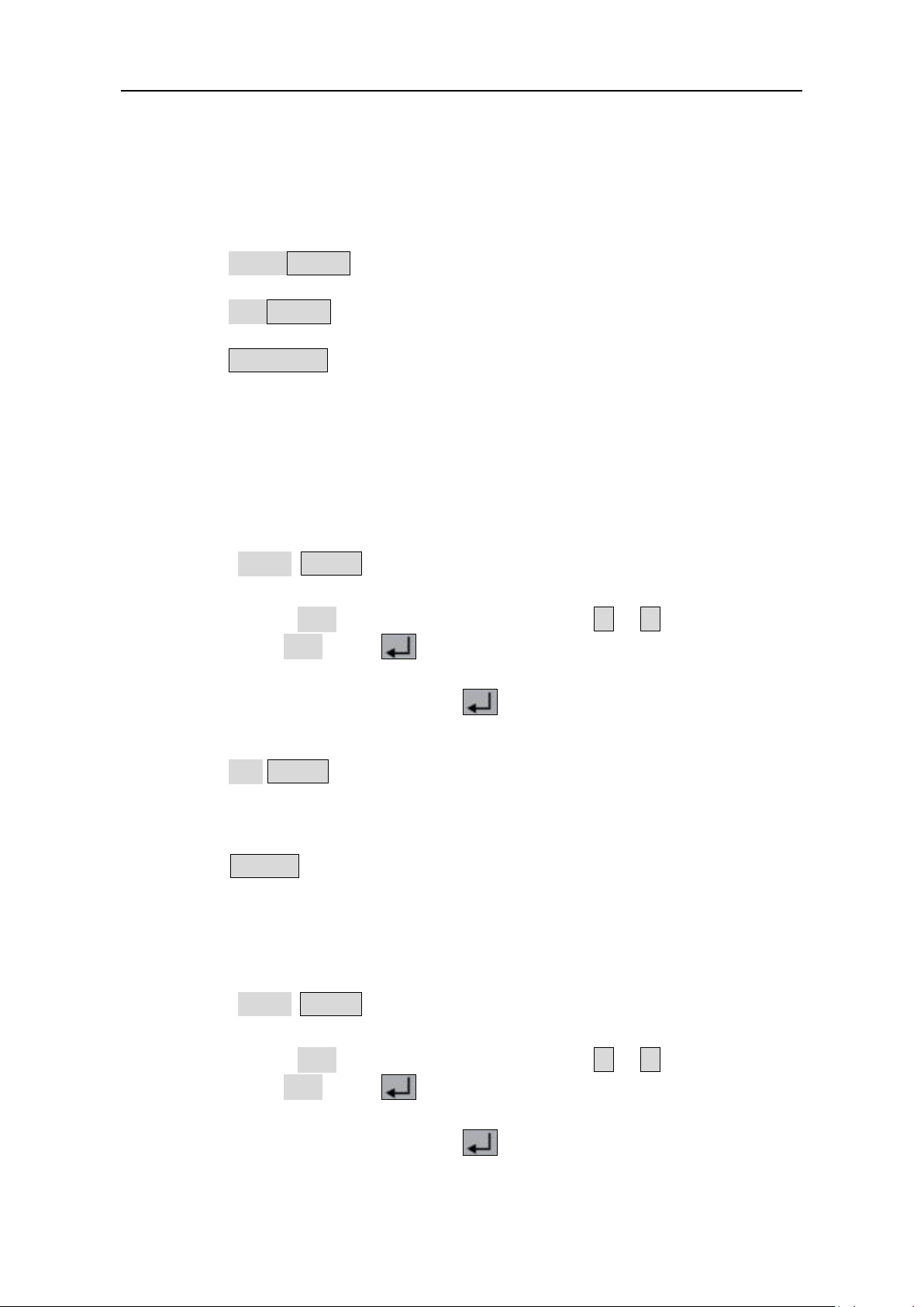
4.2 Set the Output Voltage/Current
4.2.1 Set the Output Voltage
Set the output voltage of CH1
Press the orange Volt/CV key, the first digit of the CH1 set voltage is flashing,
indicating the value is editable. There are two methods to change the value.
Modify: Turn the knob to change the value. Press the < / > key to move the
cu rs o r. Press the knob or the key to confirm.
Input: Use the numeric keys to input, the input box of Channel 1 output voltage will
pop up. Enter a desired value. Press the key to confirm.
Set the output voltage of CH2
Press the blue Volt/CV key to enter edit mode. You can set the value in the same way
as CH1 above.
Set the output voltage of CH3
Press the Volt CH3 key to enter edit mode. You can set the value in the same way as
CH1 above.
4.2.2 Set the Output Current
Set the output current of CH1
Press the orange Curr/CC key, the first digit of the CH1 set current is flashing,
indicating the value is editable. There are two methods to change the value.
Modify: Turn the knob to change the value. Press the < / > key to move the
cu rs o r. Press the knob or the key to confirm.
Input: Use the numeric keys to input, the input box of Channel 1 output current will
pop up. Enter a desired value. Press the key to confirm.
Set the output current of CH2
Page 13

4.Front Panel Operation
10
Press the blue Curr/CC key to enter edit mode. You can set the value in the same way
as CH1 above.
Set the output current of CH3
Press the Curr CH3 key to enter edit mode. You can set the value in the same way as
CH1 above.
Note: If the input value is out of the rated range, the box prompts "ERROR"; you need to
input another value within the rated range.
4.3 Over Voltage/Current Protection
When the Over Voltage Protection (O.V.P) or Over Current Protection (O.C.P) is enabled,
once the output voltage/current reaches the set value of O.V.P/O.C.P, the instrument will
cut off the output, a warning will show on the screen.
Note:
When the instrument disables the output due to protection, after you make some
adjustments, the channel must be restarted to output normally.
This function can keep the power output from exceeding the load rating to protect the
load.
4.3.1 Set O.V. P
Set the O.V.P of CH1
Press the orange Volt/CV key, the first digit of the CH1 set voltage is flashing. Press
the ▼ key, the first digit of the CH1 O.V.P is flashing, indicating the value is editable.
There are two methods to change the value.
Modify: Turn the knob to change the value. Press the < / > key to move the
cu rs o r. Press the knob or the key to confirm.
Input: Use the numeric keys to input, the input box of Channel 1 limit voltage will
pop up. Enter a desired value. Press the key to confirm.
Set the O.V. P of CH2
Press the blue Volt/CV key, then press the ▼ key to enter edit mode. You can set the
value in the same way as CH1 above.
Set the O.V. P of CH3
Press the Volt CH3 key, then press the ▼ key to enter edit mode. You can set the
value in the same way as CH1 above.
4.3.2 Set O.C.P
Set the O.C.P of CH1
Page 14

4.Front Panel Operation
11
< / >
< / >
Press the orange Curr/CC key, the first digit of the CH1 set current is flashing. Press
the ▼ key, the first digit of the CH1 O.C.P is flashing, indicating the value is editable.
There are two methods to change the value.
Modify: Turn the knob to change the value. Press the < / > key to move the
cu rs o r. Press the knob or the key to confirm.
Input: Use the numeric keys to input, the input box of Channel 1 limit current will
pop up. Enter a desired value. Press the key to confirm.
Set the O.C.P of CH2
Press the blue Curr/CC key, then press the ▼ key to enter edit mode. You can set the
value in the same way as CH1 above.
Set the O.C.P of CH3
Press the Curr CH3 key, then press the ▼ key to enter edit mode. You can set the
value in the same way as CH1 above.
4.4 Programmable Output
The programmable output function can preset up to 100 groups of timing parameters.
When you turn on the programmable output, the instrument will output the
pre-specified voltage, current in pre-specified time.
4.4.1 Data View
Press the Program key. The Data view menu is selected.
(1) The Memory sub menu is selected. Press the
External.
(2) Press the ▼ key to select Import submenu. Press the key to import data.
(3) Press the ▼ key to select Export submenu. Press the key to export data.
Note: When the memory is set as External, the programmable data file will be
export to U disk, the directory is P6181\Program.
(4) Press the ▼ key to select Clear Data submenu. Press the key to clear data.
key to select Internal or
4.4.2 Output Set
Press the Program key, turn the knob to select [Output Set].
(1) The Cycle Mode sub menu is selected. Press the
Loop.
(2) Press the ▼ key to select Start Point submenu. Use the numeric keys to input (1 to
100), press the key to confirm.
key to select Oder or
Page 15

4.Front Panel Operation
12
< / >
< / >
←
< / >
(3) Press the ▼ key to select Stop Point submenu. Use the numeric keys to input (1 to
100), press the key to confirm.
(4) Press the ▼ key to select Start submenu. Press the
channel (CH1, CH2 or ALL), press the key to enter the data processing interface
and output the selected channel.
key to select the
4.4.3 Data process
You can set the programmable parameters of CH1 and CH2, including voltage, current and
output time. This function allows up to 100 parameter groups of each channel.
Press the Program key, turn the knob to select [Data process].
Edit:
(1) The Edit sub menu is selected. The operation instruction shows on the screen. Press
the key to enter the data processing interface.
(2) In the data processing interface, Press the
right. Press the ▲ / ▼ key to move the cursor up and down. Turn the knob to move
the cursor between CH1 and CH2. Use the After selecting the parameter, use the
numeric keys to enter a desired value, press the key to confirm.
key to move the cursor left and
Figure 4-1 Data processing Interface
(3) Press
Graph process is used to configure the graphical display in the Data processing
interface.
(1) Press the ▼ key to select Graph process submenu. Press the key to enter the
editing interface.
(2) In the Graph processing interface, Press the
and right. Press the ▲ / ▼ key to move the cursor up and down. Press the key
to check or uncheck the item. If the item is checked, the corresponding line will be
to back to sub menu selection.
key to move the cursor left
Page 16

4.Front Panel Operation
13
←
< / >
< / >
< / >
displayed in the chart in the data processing interface.
(3) Press
to back to sub menu selection.
4.4.4 Turn On/Off Programmable Output
In the data processing interface:
Independent Mode
Press orange ON/OFF key to turn on/off the programmable output of Channel 1.
Press blue ON/OFF key to turn on/off the programmable output of Channel 2.
Parallel/Series Mode
Press orange ON/OFF key to turn on/off the programmable output.
In the data processing interface:
Press the ▼ key to select Start submenu. Press the
(CH1, CH2 or ALL), press the key to enter the data processing interface and output
the selected channel.
Note:
In the process of programmable output, closing the channel output will reset the timer;
turning on the channel again will restart the programmable output and the timer.
key to select the channel
4.5 Save Settings/Auto Record
4.5.1 Save Settings
You can store, recall and delete current setting parameters. The storage memory could be
set as internal or external (USB flash device). Up to 100 groups of settings can be saved.
Press the Record key. The Save Settings menu is selected.
(1) The Memory sub menu is selected. Press the
External.
(2) Press the ▼ key to select Save submenu. Press the < / > key to select the channel
(CH1, CH2 or CH3), press the key to save the setting of the selected channel.
Note: When the memory is set as External, the setting will be saved to U disk as a
CSV file, the directory is P6181\Record_Option.
(3) Press the ▼ key to select Delete submenu. Press the key, a red box will show in the
table, indicating the selected item. Press the ▲ / ▼ key to select. Press the
key to select Internal or
key to turn the page. Press the key to delete. Press ← to back to
Page 17

4.Front Panel Operation
14
<
←
< / >
< / >
< / >
sub menu selection.
(4) Press the ▼ key to select Recall submenu. Press the key, a red box will show in
the table, indicating the selected item. Press the ▲ / ▼ key to select. Press the
/ > key to turn the page. Press the key to recall. Press
menu selection.
to back to sub
4.5.2 Auto Record
Press the Record key, turn the knob to select [Auto Record].
(1) The Memory sub menu is selected. Press the
External.
(2) Press the ▼ key to select Interval submenu. Use the numeric keys to set the record
interval, press the key to confirm.
(3) Press the ▼ key to select Points submenu. Use the numeric keys to set the points,
press the key to confirm.
(4) Press the ▼ key to select Record Status submenu. Press the
the channel (CH1, CH2 or CH3), press the key to start recording the output of
the selected channel. Press the key again to stop recording. During recording,
key to select Internal or
key to select
the icon will be lighted on the status bar.
Note: When the memory is set as External, the record file will be saved to U disk as a
CSV file, the directory is ODP3XXX\Record_Auto (ODP3XXX is the model).
4.5.3 View Record
Press the Record key, turn the knob to select [View Record].
(1) Press the ▼ key to select Memory submenu. Press the
Internal or External.
(2) When the Memory is set as Internal, press the ▲ key to select Read submenu. Press
key to select
Page 18

4.Front Panel Operation
15
< / >
< / >
< / >
< / >
the
read the recording file of the selected channel. After reading successfully, if the
display mode is set as Table, a red box will show in the table, indicating you can press
the
When the Memory is set as External, press the ▲ key to select Export submenu.
key to select the channel (CH1, CH2 or CH3), press the key to
key to turn the page. Press ← to back to sub menu selection.
Press the
to export the recording file of the selected channel onto the U disk. The directory
is P6181\Record_Auto
(3) Press the ▼ key to select Display submenu. Press the
or Table.
key to select the channel (CH1, CH2 or CH3), press the key
Graph display mode
key to select Graph
Table display mode
(4) Press the ▼ key to select Clear submenu. Press the key to clear the recording
file.
4.6 Output mode
Output mode can simplify the parameter inputting of CH1 and CH2. Output mode setting
Page 19

4.Front Panel Operation
16
Parallel
CH1 and CH2
in parallel
CH3
+-+-
CH2CH1
I
2
R
L
I
1
I
L
IL = I1 + I
2
POWER SUPPLY
is only for CH1 and CH2, without affecting CH3. There are four output modes:
Independent Output
The parameter of each channel can be set independently.
Parallel track
When CH1 and CH2 are connected in parallel, you can select this mode to simplify
the parameter inputting. You just need to set the parameters of the combined
channel. The voltage rating is same as the single channel; the current rating is the
sum of CH1 and CH2 current rating.
Press the orange ON/OFF key to turn on/off the combined channel.
The connection method of the parallel connection of CH1 and CH2 is as shown in the
figure below.
Series track
When CH1 and CH2 are connected in series, you can select this mode to simplify the
parameter inputting. You just need to set the parameters of the combined channel.
The voltage rating is the sum of CH1 and CH2 voltage rating; the current rating is
same as the single channel.
Press the orange ON/OFF key to turn on/off the combined channel.
Page 20

4.Front Panel Operation
17
Series
CH1 and CH2
in series
CH3
+-+-
CH2CH1
V
2
R
L
V
1
V
L
+-
V
L
= V
1
+ V
2
POWER SUPPLY
The connection method of the series connection of CH1 and CH2 is as shown in the
figure below.
Channel track
In independent output mode, set the output parameters of CH1 and CH2, and then
enter the channel track mode, if the parameters of any one channel are changed, the
other channel will change proportionally.
For example, in independent output mode, set the CH1 voltage to 2V, current to 1A;
set the CH2 voltage to 4V, current to 2A. After entering channel track mode, if CH1
voltage is set to 6V, CH2 voltage will be adjusted to 12V proportionally. If CH1 current
is set to 2A, CH2 current will be adjusted to 4A proportionally.
Note: If the setting value is out of the rated range, it will be set to the maximum.
To set the output mode:
(1) Press the Utility key. The Output mode menu is selected.
(2) Press the ▲ / ▼ key to select the output mode. Press the key to check and
enter the selected mode.
Page 21

4.Front Panel Operation
18
< / >
<
>
Output
VOLT
CURR
CH1
CH2
CH3
Parallel
12.000V
6.000A
Series
36.000V
2.000A
4.7 Utility Settings
4.7.1 Language
Press the Utility key, turn the knob to select [Utility]. The Language sub menu is selected.
Press the < / > key to choose the desired language. The supported languages
include: Chinese, English and so on.
4.7.2 Brightness
Press the Utility key, turn the knob to select [Utility]. Press the ▼ key to select
Brightness submenu. Press the < / > key to adjust the screen brightness. The
brightness can be set to 0%, 25%, 50%, 75%, 100%.
4.7.3 Beeper
Press the Utility key, turn the knob to select [Utility]. Press the ▼ key to select Beeper
submenu. Press the
icon will be lighted on the status bar. When the system prompts the instrument will
make a buzzing sound, e.g. cutting off the output due to O.V.P/O.C.P.
key to turn on/off the beeper. When the beeper is on, the
4.7.4 Clock
Press the Utility key, turn the knob to select [Utility]. Press the ▼ key to select Clock
submenu. Use the numeric keys to input, press the key to confirm. Press the
key to move the cursor.
/
4.8 System Info
4.8.1 View System Information
Press the Utility key, turn the knob to select [Info]. The Info sub menu is selected. You
can view the version, serial number, and checksum.
4.8.2 Set as Default
Press the Utility key, turn the knob to select [Info]. Press the ▼ key to select Default
submenu. Press the key to use the factory defaults, see table below.
Output
settings
12.00V 2.000A
Page 22

4.Front Panel Operation
19
Output
VOLT
CURR
CH1
CH2
CH3
Parallel
MAXOUT+1V
2*(MAXOUT+0.1A)
Series
2*(MAXOUT+1V)
MAXOUT+0.1A
Output mode
Independent mode
Brightness
50%
Beeper
On
Baud
115200
Data Bits
8
Odd-Even
None
Stop Bits
1
IP
192.168.001.099
Subnet Mask
255.255.255.000
Gateway
192.168.001.001
Port
3000
Settings
Memory
Internal
Save
CH1
Memory
Internal
Interval
1
Points
1000
Record
Status
Read
CH1
Memory
Internal
Display
Graph
Data view
Memory
Internal
Cycle Mode
Order
Start Point
1
Stop Point
100
Data
process
Graph
process
Limit
settings
Utility
MAXOUT+1V MAXOUT+0.1A
Serial
Port
LAN Set
Save
Auto
Record
Program
Record
CH1
View
Record
Output Set
SET&READ(CH1:VOLT,CURR;CH2:VOLT,CURR)
4.8.3 Update
Press the Utility key, turn the knob to select [Info]. Press the ▼ key to select Update
submenu. Press the key to update firmware.
Page 23

4.Front Panel Operation
20
< / >
< / >
< / >
< / >
< / >
4.9 Port Settings
4.9.1 Serial port
Press the Utility key, turn the knob to select [Port Set]. The Serial sub menu is selected.
(1) Press the key to enter sub menu. The Baud is selected. Press the
key to select the desired baud rate from 1200, 2400, 4800, 9600, 19200, 38400,
57600 or 115200. The default is 115200. Make sure that the baud rate matches that
of the computer.
(2) Press the ▼ key to select Data Bits. Press the
(3) Press the ▼ key to select Odd-Even. Press the
Even.
(4) Press the ▼ key to select Stop Bits. Press the
Press ← to back to sub menu selection.
key to select 6, 7, or 8.
key to select None, Odd, or
key to 1 or 2.
4.9.2 LAN Set
Press the Utility key, turn the knob to select [Port Set]. Press the ▼ key to select Lan Set
submenu.
(1) Press the key to enter edit mode. Set the IP address, subnet mask, gateway,
and port. Use the numeric keys to input, press the key to confirm. Press the
cursor up and down. Press ← to back to sub menu selection.
(2) Restart the instrument for the parameter changes to take effect.
key to move the cursor left and right. Press the ▲ / ▼ key to move the
4.9.3 LCD Test
The instrument has a screen self test function, which can test the LCD screen.
Press the Utility key, turn the knob to select [Port Set]. Press the ▼ key to select Lcd
Test submenu.
(1) Press the key to enter the screen test interface.
(2) Press the ▲ key to switch the color between red, green, and blue. Observe if the
screen has severe color shift, spot, scuffing, or other defect.
Press the key to exit the test.
(3
)
4.9.4 Key Test
The instrument provides the key self testing, which can test the keys on the front panel.
Press the Utility key, turn the knob to select [Port Set]. Press the ▼ key to select Key
Test submenu.
(1) Press the key to enter the key test interface.
(2) Each shape on the test interface represents a front panel key. Press any front panel
key, the corresponding shape on the test interface will turn green.
Press the key to exit the test.
(
3)
Page 24

5.Troubleshooting
21
5. Troubleshooting
1. The instrument is powered on but no Display.
Check if the power is connected properly.
Check if the fuse which is below the AC Power socket is used appropriately and
in good condition (the cover can be pried open with a straight screwdriver).
Restart the instrument after the steps above.
If the problem still exists, please contact PeakTech for our service.
2. The output is abnormal:
Check if the output voltage is set to 0V. If so, set it to other value.
Check if the output current is set to 0A. If so, set it to other value.
When in programmable output status, check if there is any voltage/current
value is set to 0. If so, set it to other value.
If the problem still exists, please contact Peaktech for our service.
3. Cannot identify the USB device correctly:
Check if the USB device is in good condition.
Check if the used USB device is a flash device, note a hard disk cannot be
supported.
Restart the instrument and insert your USB flash device again.
If the problem still exists, please contact PeakTech for our service.
4. Appendix
6.1 Appendix A: Packaging
(The accessories subject to final delivery.)
Standard Accessories:
Power Cord
CD Rom
USB Cable
Fuse
Page 25

6.Appendix
22
test leads
Warn
Options:
Banana plug to
crocodile clip
6.2 Appendix B: General Care and Cleaning
General Care
Do not store or leave the instrument where the liquid crystal display could be
exposed to direct sunlight for long periods of time.
Caution: To avoid any damage to the instrument, do not exposed it to any sprays,
liquids, or solvents.
Cleaning
Inspect the instrument as often as operating conditions require.
To clean the instrument exterior, perform the following steps:
1. Wipe the dust from the instrument surface with a soft cloth. Take care not to
scratch the transparent LCD protection screen when cleaning.
2. Disconnect power before cleaning your instrument. Clean the instrument with a
damp soft cloth (not dripping with water). It is recommended to clean with soft
detergent or fresh water. To avoid damage to the instrument, do not use any
corrosive chemical cleaning agents.
ing: Before re applying power, ensure that the instrument is completely
dry, avoiding any electric shock or electrical short circuit resulting
from moisture.
 Loading...