

Page 1

PeakTech
®
4094, 4095, 4096
Operation manual
Graphical Bench-Type Multimeter
Page 2

i
Table of Contents
1.Safety Information ................................................................................................ 1
Safety Terms and Symbols ......................................................................................... 1
General Safety Requirements ..................................................................................... 2
Measurement Limits .................................................................................................... 3
Main Input Terminals (HI Input and LO Input) Measurement Limits .......................................... 3
Current Input Terminal (I) Measurement Limits ......................................................................... 4
Sense Terminals (HI Sense and LO Sense) Measurement Limits ............................................ 4
Measurement Category ............................................................................................... 4
2.Quick Start ........................................................................................................... 6
General Inspection ....................................................................................................... 6
Dimensions .................................................................................................................. 7
Foot Stool Adjustment ................................................................................................. 7
Front Panel Overview .................................................................................................. 8
Rear Panel Overview .................................................................................................. 11
User Interface ................................................................ ............................................. 12
AC Power Input Setting ............................................................................................. 13
Power On .................................................................................................................... 14
Measurement Connections ....................................................................................... 14
3.Functions and Operations ................................................................................... 16
To Set The Range ....................................................................................................... 16
Measurement Speed and Resolution ........................................................................ 18
Basic Measurement Functions.................................................................................. 19
Measuring DC Voltage ............................................................................................................. 19
Measuring AC Voltage ............................................................................................................. 20
Measuring DC Current ............................................................................................................. 22
Page 3

ii
Measuring AC Current ............................................................................................................. 23
Measuring Resistance ............................................................................................................. 24
Continuity Test ......................................................................................................................... 27
Diode Test ................................................................................................................................ 28
Measuring Capacitance ........................................................................................................... 29
Measuring Frequency and Period ............................................................................................ 30
Measuring Temperature .......................................................................................................... 32
Dual Display ............................................................................................................... 34
Triggering ................................................................................................................... 36
Auto Trigger ............................................................................................................................. 36
Single Trigger ........................................................................................................................... 36
External Trigger ....................................................................................................................... 37
Math ............................................................................................................................ 38
Statistics ................................................................................................................................... 38
Limits ........................................................................................................................................ 38
dB/dBm .................................................................................................................................... 39
Relative Value .......................................................................................................................... 40
Display ........................................................................................................................ 41
Number .................................................................................................................................... 41
Bar Meter ................................................................................................................................. 41
Trend Chart .............................................................................................................................. 42
Histogram ................................................................................................................................. 43
Data Record Function ................................................................................................ 45
Manual Record ......................................................................................................................... 45
Auto Record ............................................................................................................................. 46
Port Configuration ..................................................................................................... 48
Serial ........................................................................................................................................ 48
Trigger ...................................................................................................................................... 48
Page 4

iii
Output ...................................................................................................................................... 48
Net Type .................................................................................................................................. 49
LAN........................................................................................................................................................ 49
Utility Menu................................................................................................................. 49
Language ................................................................................................................................. 49
Backlight .................................................................................................................................. 49
Clock ........................................................................................................................................ 49
SCPI ......................................................................................................................................... 49
Default ...................................................................................................................................... 49
System Info .............................................................................................................................. 53
Update firmware ....................................................................................................................... 53
LCD Test .................................................................................................................................. 54
Key Test ................................................................................................................................... 54
4.Measurement Tutorial ......................................................................................... 56
Loading Errors (DC Voltage) ..................................................................................... 56
True RMS AC Measurements .................................................................................... 57
Loading Errors (AC Voltage) ..................................................................................... 59
5.Troubleshooting ................................................................................................. 60
6.Technical Specifications ...................................................................................... 61
7.Appendix ............................................................................................................ 68
Appendix A: Enclosure ............................................................................................ 689
Appendix B: General Care and Cleaning ................................................................ 689
Appendix C: Line Fuse Replacement ....................................................................... 70
Page 5

1
1. Safety Information
Safety Terms and Symbols
Safety Terms
Terms in this Manual. The following terms may appear in this manual:
Warning: Warning indicates the conditions or practices that could result
in injury or loss of life.
Caution: Caution indicates the conditions or practices that could result in
damage to this product or other property.
Terms on the Product. The following terms may appear on this product:
Danger: It indicates an injury or hazard may immediately happen.
Warning: It indicates an injury or hazard may be accessible potentially.
Caution: It indicates a potential damage to the instrument or other property might
occur.
Safety Symbols
Symbols on the Product. The following symbol may appear on the product:
Direct current (DC)
Warning, risk of electric shock
Alternating current (AC)
Caution, risk of danger (refer to this manual for
specific Warning or Caution information)
Both direct and alternating current
Conforms to European Union directives
Ground terminal
Chassis Ground
IEC Measurement Category I. The maximum measurable voltage is 1000 Vpk in the HI -LO
terminal.
IEC Measurement Category II. Inputs may be connected to AC mains power (up to 600
VAC) under Category II overvoltage conditions.
This product complies with the WEEE Directive (2002/96/EC) marking equipment. The
affixed product label indicates that you must not discard this electrical/electronic product in
domestic household waste.
Page 6

1.General Safety Requirements
2
General Safety Requirements
Before any operations, please read the following safety precautions to avoid
any possible bodily injury and prevent this product or any other products
connected from damage. In order to avoid any contingent danger, this
product is only used within the range specified.
Check AC power input setting according to the standards in your own country
(see page 13, AC Power Input Setting).
Use Proper Power Cord. Use only the power cord supplied with the product
and certified to use in your country.
Product Grounded. This instrument is grounded through the power cord
grounding conductor. To avoid electric shock, the grounding conductor must
be grounded. The product must be grounded properly before any connection
with its input or output terminal.
Limit operation to the specified measurement category, voltage, or
amperage ratings.
Check all Terminal Ratings. To avoid instrument damage and the risk of
electric shock, check all the Measurement Limits and markers of this product.
Refer to the user's manual for the Measurement Limits before connecting to
the instrument. Do not exceed any of the Measurement Limits defined in the
following section.
Do not operate without covers. Do not operate the instrument with covers or
panels removed.
Use Proper Fuse. Use only the specified type and rating fuse for this
instrument.
Avoid exposed circuit. Do not touch exposed junctions and components
when the instrument is powered.
Do not operate if in any doubt. If you suspect damage occurs to the
instrument, have it inspected by qualified service personnel before further
operations.
Use your instrument in a well-ventilated area. Inadequate ventilation may
cause increasing of temperature or damages to the device. Please keep well
ventilated and inspect the intake regularly.
Do not operate in wet conditions. In order to avoid short circuiting to the
interior of the device or electric shock, please do not operate in a humid
environment.
Do not operate in an explosive atmosphere.
Keep product surfaces clean and dry.
Only the qualified technicians can implement the maintenance.
Page 7

1.General Safety Requirements
3
Measurement Limits
The protection circuitry of the multimeter can prevent damage to the instrument
and protect against the danger of electric shock, when the Measurement Limits
are not exceeded. To ensure safe operation of the instrument, do not exceed the
Measurement Limits shown on the front panel, it is defined as follows:
The user-replaceable 10 A current-protection fuse is on the front panel. To
maintain protection, replace fuse only with fuse of the specified type and rating.
About the specified type and rating of the fuse, please refer to "7 Current Terminal
Fuse" in "Front Panel Overview" on page 9.
Main Input Terminals (HI Input and LO Input) Measurement
Limits
The HI and LO input terminals are used for voltage, resistance, continuity,
frequency (period), capacitance, diode, and temperature test measurements. Two
Measurement Limits are defined for these terminals:
HI Input to LO Input Measurement Limit
The Measurement Limit from HI Input to LO Input is 1000 VDC or 750 VAC,
which is also the maximum voltage measurement. This limit can also be
expressed as 1000 Vpk maximum.
LO Input to Ground Measurement Limit
The LO input terminal can safely "float" a maximum of 500 Vpk relative to
ground, where ground is defined as the Protective Earth Conductor in the AC
mains power cord connected to the instrument.
As implied by the above limits, the Measurement Limit for the HI input terminal is
a maximum of 1500 Vpk relative to ground when LO Input is at its maximum of
500 Vpk relative to ground.
Page 8

1.General Safety Requirements
4
Current Input Terminal (I) Measurement Limits
The Measurement Limit from the current input terminal (I) to the LO Input terminal
is 10 A (DC or AC). Note that the current input terminals will always be at
approximately the same voltage as the LO Input terminal, unless a current
protection fuse is open.
Sense Terminals (HI Sense and LO Sense) Measurement
Limits
The HI and LO sense terminals are used for four-wire resistance measurements.
The Measurement Limit from HI Sense to LO Input is 200 Vpk.
The Measurement Limit from HI Sense to LO Sense is 200 Vpk.
The Measurement Limit from LO Sense to LO Input is 2 Vpk.
Note: The 200 Vpk limit on the sense terminals is the Measurement Limit.
Operational voltages in resistance measurements are much lower – up to ± 12 V
in normal operation.
Measurement Category
The safety rating of the multimeter:
1000 V, CAT I
IEC Measurement Category I. The maximum measurable voltage is 1000 Vpk in
the HI -LO terminal.
600 V, CAT II
IEC Measurement Category II. Inputs may be connected to AC mains power (up
to 600 VAC) under Category II overvoltage conditions.
Page 9

1.General Safety Requirements
5
Measurement category definition
Measurement CAT I applies to measurements performed on circuits not directly
connected to the AC mains. Examples are measurements on circuits not derived
from the AC mains and specially protected (internal) mains- derived circuits.
Measurement CAT II applies to protect against transients from energyconsuming equipment supplied from the fixed installation, such as TVs, PCs,
portable tools, and other household circuits.
Measurement CAT III applies to protect against transients in equipment in fixed
equipment installations, such as distribution panels, feeders and short branch
circuits, and lighting systems in large buildings.
Measurement CAT IV applies to measurements performed at the source of the
low- voltage installation. Examples are electricity meters and measurements on
primary over current protection devices and ripple control units.
Page 10

6
2. Quick Start
General Inspection
After you get a new multimeter, it is recommended that you should make a check
on the instrument according to the following steps:
1. Check whether there is any damage caused by transportation.
If it is found that the packaging carton or the foamed plastic protection cushion
has suffered serious damage, do not throw it away first till the complete device
and its accessories succeed in the electrical and mechanical property tests.
2. Check the Accessories
The supplied accessories have been already described in the Appendix A:
Enclosure of this Manual. You can check whether there is any loss of
accessories with reference to this description. If it is found that there is any
accessory lost or damaged, please get in touch with the distributor of
PEAKTECH responsible for this service or the PEAKTECH's local offices.
3. Check the Complete Instrument
If it is found that there is damage to the appearance of the instrument, or the
instrument can not work normally, or fails in the performance test, please get in
touch with the PEAKTECH's distributor responsible for this business or the
PEAKTECH's local offices. If there is damage to the instrument caused by the
transportation, please keep the package. With the transportation department or
the PEAKTECH's distributor responsible for this business informed about it, a
repairing or replacement of the instrument will be arranged by the PEAKTECH.
Page 11

7
Dimensions
Foot Stool Adjustment
Unfold the foot stool on the bottom of the multimeter.
235 mm
110 mm
295 mm
Page 12

8
Front Panel Overview
Figure 2-1 Front panel overview
Ite
m
Name
Description
1
LCD
Display the user interface
2
Menu selection
Keys
Activate the corresponding menu
3
Operation Keys
Save
Collect data in manual record. The instrument saves
current reading each time the Save key is pressed.
See page 45, Manual Record.
Record
Access menus of manual record and auto record.
See page 45, Data Record Function.
Run/Stop
When the trigger source is set as Auto, start or stop
auto trigger.
When the trigger source is set as Single, the
instrument issues one trigger each time this key is
pressed.
2
3
4
5
12
1
6
7
8
11 13
9
10
Page 13

9
Math
Perform math operations (statistic, limits, dB/dBm,
REL) on the measurement results.
Utility
Set the auxiliary system function, including Language,
Backlight, Clock, SCPI, Set to default, System
information, LCD test, Key test.
Port
Set Serial, Trigger, Output connector, Net Type.
4
HI and LO Sense
Terminals
Signal input terminals, used for four-wire resistance
measurements.
5
HI and LO Input
Terminals
Signal input terminals, used for voltage, resistance,
continuity, frequency (period), capacitance, diode, and
temperature test measurements.
6
Range/Direction
Keys
When the Range softkey is shown on the right menu,
you can press the key to switch between auto
and manual range. Press to enable manual
range, and increase or decrease the measurement
range.
When setting a parameter, press to move the
cursor, press to increase or decrease the value.
7
Current Terminal
Fuse
The rating is 10 A, 250 VAC.
To replace the fuse:
Turn off the multimeter and remove the power cord.
Use a flat-blade screw driver to turn the fuse holder
counter-clockwise, and pull out the fuse holder. Put
the new specified fuse into the fuse holder, and insert
the assembly back into the instrument, turning the
fuse holder clockwise to lock it in place.
Page 14

10
8
AC/DC Current
Input Terminals
Signal input terminals, used for AC/DC current
measurements.
9
Power button
Turn on/off the multimeter.
10
Measurement
Function Keys
DC or AC voltage measurements
DC or AC current measurements
Resistance, continuity, and diode
measurements
Capacitance measurements
Frequency/Period measurements
Temperature measurements
11
Graph
Choose what is displayed: number, bar meter, trend
chart, or histogram.
12
Dual
Press this key to display the function list on the right
menu, select a function, if the function is supported,
the reading will be displayed in the Vice Display.
13
USB Connector
Connect with an external USB device, such as
connect a USB memory device to the instrument.
Page 15

11
Rear Panel Overview
Figure 2-2 Rear panel overview
Ite
m
Name
Description
1
External Trigger
Input
Trigger the multimeter by connecting a trigger pulse.
The external trigger source must be selected.
( → Trigger → Source (External) )
2
Auxiliary Output
Connector
Defaults to Voltmeter Measurement Complete Output,
outputs a pulse whenever the multimeter finishes
taking a measurement to allow you to signal other
devices. This connector can also be configured to
output a pulse when limits are exceeded in Math limits
function ( → Output → Output (P/F)).
3
RS232
Connect the PC through this interface.
4
USB (type B)
Connector
This can be used to connect a USB type B controller.
Connect with an external device, such as connected
to a PC and controlled via PC software.
5
Local Area
Network (LAN)
Connector
The multimeter can be connected to the network for
remote control via this connector.
1
2
3
4
5
6
8
7
9
10
Page 16

12
6
AC Mains Line
Voltage Selector
Select a proper voltage scale according to the AC
supply used. Switch between 110 V and 220 V.
7
Line Fuse
Use the specified fuse according to the voltage scale.
To replace the fuse, see page 69, Appendix C: Line
Fuse Replacement.
Voltage
Fuse
100 - 120 V AC
250 V, F1AL
220 - 240 V AC
250 V, F0.5AL
8
AC Mains Input
AC mains input connector.
9
Chassis Ground
Screw
To ground the chassis.
10
Instrument
Cable Lock
You can lock the instrument to a fixed location using
the security lock (please buy it yourself) to secure the
instrument.
User Interface
Trigger Mode
Reading
Range Function
Operation Menus
Unit
Status Icon
Trigger Mode
Status Icon
Page 17

13
Figure 2-3 User interface (Single display)
Figure 2-4 User interface (Dual display)
AC Power Input Setting
Adopt 100 - 120 VAC or 220 - 240 VAC power source. Users should regulate the
voltage scale of the AC Mains Line Voltage Selector according to the standards
in their own country (see Figure 2-2 Rear panel overview) at the rear panel, and
use an appropriate fuse.
Voltage
Fuse
100 - 120 V AC
250 V, F1AL
220 - 240 V AC
250 V, F0.5AL
To change the voltage scale of the instrument, do the following steps:
(1) Turn off the power button at the front panel, and remove the power cord.
Secondary function reading
Primary function reading
Primary function
Display
Description
Trigger
Auto trigger
Ext
External
Icon
Description
LAN is connected
Connect as a slave device
Auto record function is running
USB memory device is
Manual record
Page 18

14
(2) Check if the fuse installed before leaving factory (250 V, F0.5AL) can match
with the selected voltage scale; if not, change the fuse. (See page 69,
Appendix C: Line Fuse Replacement.)
(3) Regulate the AC Mains Line Voltage Selector to the desired voltage scale.
Power On
(1) Connect the instrument to the AC supply using the supplied power cord.
Warning:
To avoid electric shock, the instrument must be grounded
properly.
(2) Press down the power button at the front panel, the screen shows the boot
screen.
Measurement Connections
After selecting the desired measurement function, please connect the signal
(device) under test to the multimeter according to the method below. To avoid
instrument damage, do not discretionarily switch the measurement function when
measuring.
DC Voltage Measurement
AC Voltage Measurement
DC Current Measurement
AC Current Measurement
DC Voltage
AC Voltage
DC Current
AC Current
Page 19

15
2-wire Resistance Measurement
4-wire Resistance Measurement
Continuity Test
Diode Measurement
Capacitance Measurement
Frequency/Period Measurement
Temperature Measurement
I
2-wire Resistance
I
4-wire Resistance
Open or Closed Circuit
I
Forward Bias
I
Capacitance
AC Signal
Temp Transducer
I
Page 20

16
3. Functions and Operations
To Set The Range
The instrument provides auto and manual range. In auto range, the multimeter
selects a proper range automatically according to the input signal; in manual
range, you can use the front panel key or menu softkey to set the range. The auto
range can bring a lot of convenience for users while the manual range provides
higher reading precision.
1st Method: Use the front panel key to set the range.
When the Range softkey is shown on the right menu, you can press the key
to switch between auto and manual range. Press to enable manual range,
and increase or decrease the measurement range.
2nd Method: Select the range in the measurement function menu.
Select auto range: In the measurement function menu, press the Range softkey,
select Auto.
Select manual range: In the measurement function menu, press the Range
softkey, select a range except Auto.
Page 21

17
Note:
When the input signal exceeds the current range, "overload” will be displayed.
By default, the range is set to Auto at power-on or after a reset.
Auto range is recommended if you are not sure about the measurement range in
order to protect the instrument and obtain accurate data.
The range of continuity test is fixed at 2 kΩ; the range of diode measurement is fixed at
2 V.
Page 22

18
Measurement Speed and Resolution
The instrument provides three types of measurement speed:
"Low" speed is 5 reading/s; "Mid" speed is 50 reading/s; "High" speed is 150
reading/s.
In DCV, ACV, DCI, ACI and 2-wire / 4-wire resistance measurements, the
measurement speed is selectable.
The reading resolution of P4095 is 4½.
The reading resolution of P4096 can be 4½ or 5½ digits. The selection of
measurement speed affects the reading resolution. The multimeter automatically
selects a reading resolution according to the current measurement settings.
Relationship between measurement speed and reading resolution:
Function
Measurement speed
Reading resolution
DCV
ACV
DCI
ACI
2-wire/4-wire
resistance
"Low" speed
P4095
4½ digits
P4096
5½ digits
"Mid" speed
"High" speed
4½ digits
Continuity test
Fixed at "High" speed
4½ digits
Diode
Fixed at "High" speed
4½ digits
Capacitance
Fixed at "Mid" speed
4½ digits
(only display the first four
digits)
Frequency/Peri
od
Fixed at "Mid" speed
4½ digits
Temperature
Fixed at "Mid" speed
4½ digits
Page 23

19
Basic Measurement Functions
Measuring DC Voltage
This section describes how to configure DC voltage measurements.
Operating Steps:
1. Enable the DCV measurement.
Press on the front panel to enter DCV measurement mode.
2. Connect the test lead.
3. Set the range.
Press the Range softkey to set the range. Auto range automatically selects
the range for the measurement based on the input.
Note:
1000 V input protection is available in all ranges.
P4096: 20% over range for all ranges except 1000 V range.
P4095: 10% over range for all ranges except 1000 V range.
DC Voltage
Page 24

20
If the reading exceeds 1050 V in 1000 V range, "overload" will be displayed.
4. Set the measurement speed.
Press the Speed softkey to switch between Low, Mid or High. See page 18,
Measurement Speed and Resolution.
5. Set the filter. (Optional operation)
Press the Filter softkey to turn on or off the AC filter. When the AC component
exists in the inputted DC signal, it can be filtered by the AC filter to make the
measurement data more exactly.
6. Set the input impedance. (Optional operation, only for 200 mV and 2 V
range)
Press the Input Z softkey to select "10M" or "10G", specify the input
impedance to the test leads. The default is "10M".
In the range of 200 mV or 2 V, you can choose "10G" to reduce the loading
error to the measured object caused by the multimeter (refer to Loading
Errors (DC Voltage) on page 56).
Note:
10M: Set the input impedances in all ranges to 10 MΩ.
10G: Set the input impedances in ranges of 200 mV and 2 V to 10 GΩ, while
in ranges of 20 V, 200 V and 1000 V, the impedances are still 10 MΩ.
7. Set the relative value. (Advanced operation)
Press the Rel softkey to turn on or off the relative operation. For relative
operation, the multimeter subtracts the pre-specified value of REL operation
from the actual measurement result and displays the result. See page 40,
Relative Value.
Measuring AC Voltage
This section describes how to configure AC voltage measurements.
Operating Steps:
1. Enable the ACV measurement.
Press on the front panel, press it again to enter ACV measurement
mode.
Page 25

21
2. Connect the test lead.
3. Set the range.
Press the Range softkey to set the range. Auto range automatically selects
the range for the measurement based on the input.
Note:
750 V input protection is available in all ranges.
P4096: 20% over range for all ranges except 750 V range.
P4095: 10% over range for all ranges except 750 V range.
If the reading exceeds 787.5 V in 750 V range, "overload" will be displayed.
4. Set the measurement speed.
Press the Speed softkey to switch between Low, Mid or High. See page 18,
Measurement Speed and Resolution.
5. Set the relative value. (Advanced operation)
Press the Rel softkey to turn on or off the relative operation. For relative
operation, the multimeter subtracts the pre-specified value of REL operation
AC Voltage
Page 26

22
from the actual measurement result and displays the result. See page 40,
Relative Value.
Measuring DC Current
This section describes how to configure DC current measurements.
Operating Steps:
1. Enable the DCI measurement.
Press on the front panel to enter DCI measurement mode.
2. Connect the test lead.
3. Set the range.
Press the Range softkey to set the range. Auto range automatically selects
the range for the measurement based on the input.
Note:
The multimeter uses two kinds of fuses for current protection: the 10 A
current input fuse on the rear panel and the built-in 12 A current input fuse.
DC Current
Page 27

23
P4096: 20% over range for all ranges except 10 A range.
P4095: 10% over range for all ranges except 10 A range.
If the reading exceeds 10.5 A in 10 A range, "overload" will be displayed.
4. Set the measurement speed.
Press the Speed softkey to switch between Low, Mid or High. See page 18,
Measurement Speed and Resolution.
5. Set the filter. (Optional operation)
Press the Filter softkey to turn on or off the AC filter. When the AC component
exists in the inputted DC signal, it can be filtered by the AC filter to make the
measurement data more exactly.
6. Set the relative value. (Advanced operation)
Press the Rel softkey to turn on or off the relative operation. For relative
operation, the multimeter subtracts the pre-specified value of REL operation
from the actual measurement result and displays the result. See page 40,
Relative Value.
Measuring AC Current
This section describes how to configure AC current measurements.
Operating Steps:
1. Enable the ACI measurement.
Press on the front panel, press it again to enter ACI measurement
mode.
Page 28

24
2. Connect the test lead.
3. Set the range.
Press the Range softkey to set the range. Auto range automatically selects
the range for the measurement based on the input.
Note:
The multimeter uses two kinds of fuses for current protection: the 10 A
current input fuse on the rear panel and the built-in 12 A current input fuse.
P4096: 20% over range for all ranges except 10 A range.
P4095: 10% over range for all ranges except 10 A range.
If the reading exceeds 10.5 A in 10 A range, "overload" will be displayed.
4. Set the measurement speed.
Press the Speed softkey to switch between Low, Mid or High. See page 18,
Measurement Speed and Resolution.
5. Set the relative value. (Advanced operation)
Press the Rel softkey to turn on or off the relative operation. For relative
operation, the multimeter subtracts the pre-specified value of REL operation
from the actual measurement result and displays the result. See page 40,
Relative Value.
Measuring Resistance
This section describes how to configure 2-wire and 4-wire resistance
measurements.
The multimeter provides 2-wire and 4-wire resistance measurements. When the
measured resistance is lower than 100 kΩ, the 4-wire resistance measurement is
AC Current
Page 29

25
recommended to reduce the measurement error caused by test lead resistance
and contact resistance between the probe and the testing point, because these
two resistances can not be ignored any more, compared to the measured
resistance.
Operating Steps:
1. Enable the Ω2W/Ω4W measurement.
Press on the front panel to enter resistance measurement mode.
Press the Ω2W/Ω4W softkey to switch between Ω2W and Ω4W.
(2-wire Resistance)
(4-wire Resistance)
2. Connect the test lead.
I
2-wire Resistance
Page 30

26
3. Set the range.
Press the Range softkey to set the range. Auto range automatically selects
the range for the measurement based on the input.
Note:
1000 V input protection is available in all ranges.
P4096: 20% over range for all ranges except 100 MΩ range.
P4095: 10% over range for all ranges except 100 MΩ range.
If the reading exceeds 105 MΩ in 100 MΩ range, "overload" will be
displayed.
4. Set the measurement speed.
Press the Speed softkey to switch between Low, Mid or High. See page 18,
Measurement Speed and Resolution.
5. Set the relative value. (Advanced operation)
Press the Rel softkey to turn on or off the relative operation. For relative
operation, the multimeter subtracts the pre-specified value of REL operation
from the actual measurement result and displays the result. See page 40,
Relative Value.
Tip:
If the measured resistance is small, relative operation is recommended in
order to reduce the error caused by test lead.
Both ends of the measured resistance should be placed far away from your
hands and desks that can conduct electricity; otherwise, the measurement
result might be inaccurate. The greater the measured resistance is, the
greater the affect will be.
I
4-wire Resistance
Page 31

27
Continuity Test
This section describes how to configure continuity test.
Operating Steps:
1. Enable the continuity test.
Press on the front panel, press it again to enter continuity test mode.
2. Connect the test lead.
3. Set the beeper.
Press the Beeper softkey to enable or disable the beeper. When the beeper is
enabled, the reading is below 30 Ω, the multimeter will beep continuously.
4. Set the short-circuit resistance.
Press the Threshold softkey to set the short-circuit resistance.
Press to move the cursor, press to increase or decrease the
value. The range for P4096 is 1 Ω to 2400 Ω; the range for P4095 is 1 Ω to
1100 Ω. The default is 50 Ω.
Open or Closed Circuit
I
Page 32

28
5. Continuity measurements behave as follows:
P4096
P4095
Display and beep
≤ Short-circuit
resistance
≤ Short-circuit
resistance
Displays measured resistance
and beeps (if beeper enabled)
Short-circuit
resistance to 2.4
kΩ
Short-circuit
resistance to 1.1
kΩ
Displays measured resistance
without beeping
> 2.4 kΩ
> 1.1 kΩ
Displays "Open" with no beep
Diode Test
This section describes how to configure diode test.
Operating Steps:
1. Enable the diode test.
Press on the front panel, press it twice to enter diode test mode.
2. Connect the test lead.
3. Set the beeper.
Press the Beeper softkey to enable or disable the beeper. When the beeper is
enabled, the diode is connected, the multimeter will beep continuously.
Forward Bias
I
Page 33

29
4. Diode measurements behave as follows:
P4096
P4095
Display and beep
0 to 2 V
0 to 3 V
Displays measured voltage, and the multimeter
beeps when the voltage is below 0.7 V (if beeper
enabled)
> 2 V
> 3 V
Displays "Open" with no beep
Measuring Capacitance
This section describes how to configure capacitance measurements.
Operating Steps:
1. Enable the capacitance measurement.
Press on the front panel to enter capacitance measurement mode.
2. Connect the test lead.
Tip: Please short contact the two feet of an electrolytic capacitor by using a
test lead before measuring the electrolytic capacitor.
3. Set the range.
Capacitance
Page 34

30
Press the Range softkey to set the range. Auto range automatically selects
the range for the measurement based on the input.
Note:
1000 V input protection is available in all ranges.
P4096: 20% over range for all ranges except 10000 μF range.
P4095: 10% over range for all ranges except 10000 μF range.
If the reading exceeds 10500 μF in 10000 μF range, "overload" will be
displayed.
4. Set the relative value. (Advanced operation)
Press the Rel softkey to turn on or off the relative operation. For relative
operation, the multimeter subtracts the pre-specified value of REL operation
from the actual measurement result and displays the result. See page 40,
Relative Value.
Measuring Frequency and Period
When measuring AC voltage or AC current, you can use the dual display function
to obtain the measured signal’s frequency and period (see page 34, Dual
Display), or press to measure the frequency or period directly.
This section describes how to configure frequency and period measurements.
Operating Steps:
1. Enable the frequency/period measurement.
Press on the front panel to enter frequency/period measurement
mode. Press the Freq/Period softkey to switch between frequency and period.
Page 35

31
2. Connect the test lead.
3. Set the range.
Press the Range softkey to set the range. Auto range automatically selects
the range for the measurement based on the input.
Note:
Frequency range: P4096 is 20 Hz to 1 MHz; P4095 is 20 Hz to 500 kHz.
Period range: P4096 is 0.05 s to 1 μs; P4095 is 0.05 s to 2 μs.
750 V input protection is available in all ranges.
AC Signal
Page 36
32
4. Set the relative value. (Advanced operation)
Press the Rel softkey to turn on or off the relative operation. For relative
operation, the multimeter subtracts the pre-specified value of REL operation
from the actual measurement result and displays the result. See page 40,
Relative Value.
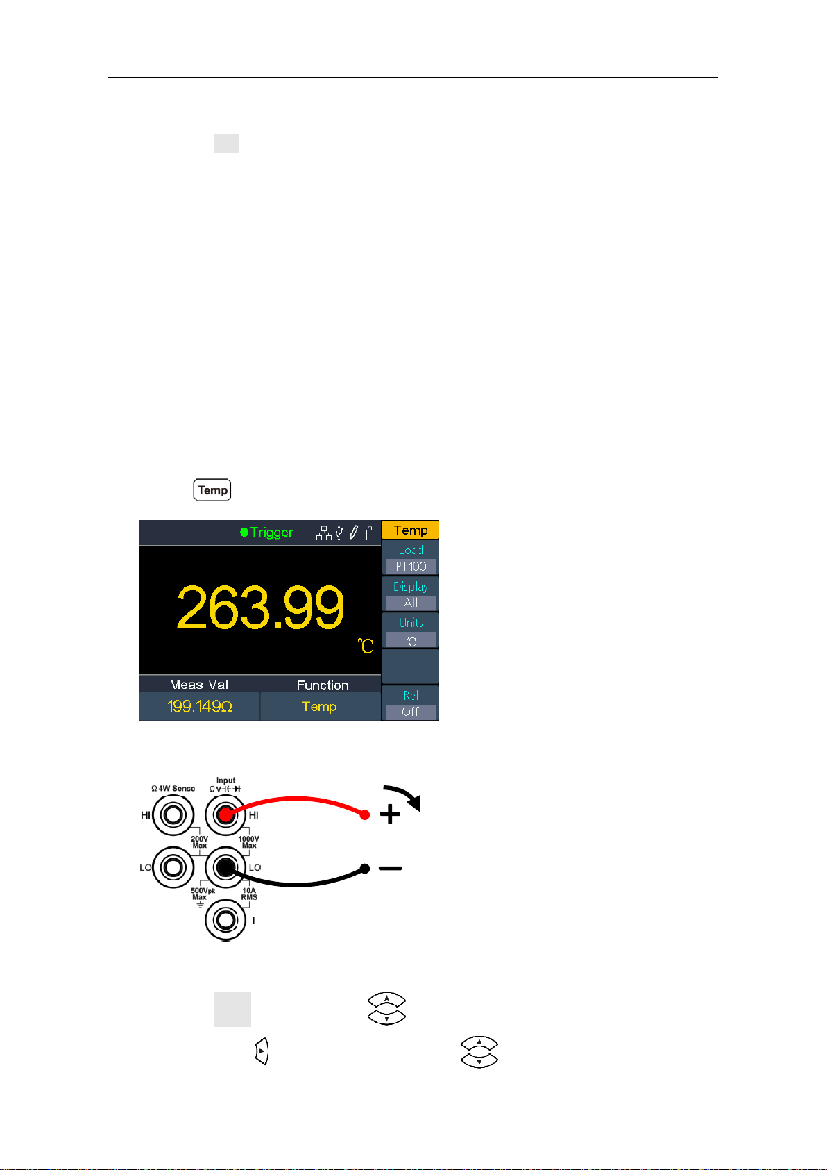
Measuring Temperature
This section describes how to configure temperature measurements. Temperature
measurements require a temperature transducer probe. The supported probes
are type B, E, J, K, N, R, S, T thermocouples, and PT100, PT385 platinum RTD
sensor.
Operating Steps:
1. Enable the temperature measurement.
Press on the front panel to enter temperature measurement mode.
2. Connect the test lead.
3. Set the sensor configuration file.
Press the Load softkey, press to select thermocouple or thermo
resistor. Press to access the list, press to select the desired
Temp Transducer
I
Page 37

33
configuration file. Press the Define softkey to view the configuration; press the
Done softkey to apply the sensor configurations.
4. Set the display.
Press the Display softkey to set the display mode of the result.
Temp Val: only the temperature value will be displayed;
Meas Val: only the measurement value will be displayed.
All: both the temperature value (on the main display) and the measurement
value will be displayed.
5. Set the temperature unit.
Press the Units softkey to display temperature in ℃ (degrees Celsius), ℉
(degrees Fahrenheit), or K (Kelvin).
The conversion relations between these units are:
℉ = (9/5) ×℃ + 32
K ≈℃ + 273.15
6. Set the relative value. (Advanced operation)
Press the Rel softkey to turn on or off the relative operation. For relative
operation, the multimeter subtracts the pre-specified value of REL operation
from the actual measurement result and displays the result. See page 40,
Relative Value.
Page 38

34
Dual Display
Using dual display function, you can view the readings of two measurement
functions simultaneously.
Figure 3-1 Dual Display
Secondary function reading
Primary function reading
Primary function
Page 39

35
Operating Steps:
1. Press one of the measurement function keys to turn on the primary
measurement function.
2. Press on the front panel, the secondary function list is shown on the
right menu, select the desired function.
3. When dual display is enabled, press to switch the primary function and
the secondary function. To configure the secondary function, you can switch it
to the primary function, configure in the right menu, then switch back.
4. Press any of the measurement function keys to disable the dual display.
The primary measurement functions and their associated secondary
measurements are: (gray back color indicates valid combinations)
Primary measurement function
DCV
DCI
ACV
ACI
FRE
Q
PERI
OD
2WR 4W
R
CAP
Secondary
DCV
DCI
ACV
ACI
FREQ
PERI
OD
2WR
4WR
CAP
Note:
The multimeter makes the primary and secondary measurements alternately,
the primary and secondary readings update respectively.
If the primary measurement uses dB or dBm scaling, the dual display can not be
enabled. When the dual display is enabled, turning on dB or dBm scaling will
automatically disable the dual display.
When the dual display is enabled, manual record function can save both of the
primary and secondary readings, auto record function can only save the primary
reading.
Page 40

36
Triggering
The multimeter provides three types of triggers: auto, single and external.
Auto Trigger
Press the front panel key, press the Trigger softkey, press the Source
softkey to select Auto. When Auto trigger is used, the instrument continuously
takes measurements, automatically issuing a new trigger as soon as a
measurement is completed.
Press the Delay softkey to select Auto or Manual.
Auto Delay
The instrument automatically determines the delay based on function, range and
measurement speed.
Manual Delay
The first sample starts one trigger delay time after the trigger. The second
sample starts one sample interval after the start of the first sample, and so on.
Set the trigger delay time: Press the Delay softkey to select Manual, press
to move the cursor, press to increase or decrease the value. The
range is 1 ms to 999,999 ms.
Set the number of samples: The multimeter takes the specified number of
readings each time a trigger signal is received. Press the Samples trigger
softkey, press to move the cursor, press to increase or decrease
the value. The range is 1 to 999,999.
Single Trigger
Press the front panel key, press the Trigger softkey, press the Source
softkey to select Single. When Single trigger is used, the instrument takes one or
specified number of readings each time the front panel key is pressed.
Trigger
Delay
Trigger
Sample
#1
Sample
#2
Sample
#3
Interval Interval Interval
Page 41

37
Auto delay is applied for single trigger, the instrument automatically determines
the delay based on function, range and measurement speed.
You can set the number of samples for single trigger. The multimeter takes the
specified number of readings each time a trigger signal is received. Press the
Samples trigger softkey, press to move the cursor, press to
increase or decrease the value. The range is 1 to 999,999.
External Trigger
Press the front panel key, press the Trigger softkey, press the Source
softkey to select External. When External trigger is used, the multimeter receives
the trigger pulse from the [Ext Trig] connector at the rear panel, triggers at the
specified edge of the pulse signal and acquires measured data.
Auto delay is applied for external trigger, the instrument automatically
determines the delay based on function, range and measurement speed.
When using external trigger, you can set the edge type for the pulse from the
[Ext Trig] connector at the rear panel. The multimeter will trigger on the
specified type of edge. Press the Trg Edge softkey to select Rising or Falling.
Page 42

38
Math
The multimeter provides these math functions: statistics, limits, dB/dBm and
relative.
Statistics
Statistics calculates the min, average, max, span, standard deviation and number
of samples of readings during the measurement.
Press the front panel key, press the Statistics softkey, press the Statistics
softkey to select Show.
Remarks
The Span value is the Max minus the Min.
Press the Clear Readings softkey to clear reading memory and restart statistics.
Limits
Limit checking indicates how many samples have exceeded specified limits, and
indicates
the signal testing result exceeded specified limits. The [AUX Output] connector at
the rear panel can be configured to output a pulse when the limits are exceeded
(see page 48, Output).
Press the front panel key, press the Limits softkey to access the limits
menu.
Press the Limits softkey to enable or disable limits.
Page 43

39
Use the High or Low softkey to specify the limits as high and low values. Press
to switch to the Center or Span softkey to specify the limits as a span around a
center value. For example, a Low limit of -5 V and a High limit of +10 V are
equivalent to a Center of 2.5 V and a Span of 15 V. When setting a parameter,
press to move the cursor, press to increase or decrease the value.
Press the Clear softkey to clear all current readings and restart limit checking.
Limit Indications: The red background color (shown below) indicates that the
displayed measurement exceeds the limits, and the multimeter beeps (if beeper
enabled).
dB/dBm
The dB and dBm scaling functions only apply to ACV and DCV measurements.
The functions allow you to scale measurements relative to a reference value.
Press the front panel key, press the dB/dBm softkey to access the menu.
Press the dB/dBm softkey to enable or disable the function.
Press the dB/dBm softkey to
dBm Function
dBm function represents the absolute value of the power. The function calculates
the power of the reference resistance according to the measured voltage, relative
to 1 mW:
dBm = 10 x log10 ( reading2 / reference resistance / 1 mW )
Press the Ref R softkey to select the reference resistance. The value may be 50,
75, 93, 110, 124, 125, 135, 150, 250, 300, 500, 600 (default), 800, 900, 1000,
1200, or 8000 Ω.
Page 44

40
dB Function
dB represents the relative value which is used in the relative operation of dBm
value. When enabled, the multimeter calculates the dBm value of the reading and
subtracts the preset dB from this value and then displays the result:
dB = 10 x Log10 ( reading2 / reference resistance / 1 mW) - dB preset
Press the Ref R softkey to select the reference resistance. The value may be 50,
75, 93, 110, 124, 125, 135, 150, 250, 300, 500, 600 (default), 800, 900, 1000,
1200, or 8000 Ω.
Press the dB Ref Value softkey to select the relative value. The relative value
must be from -120 to +120 dBm (default 0).
Relative Value
When the relative operation is turned on, the reading displayed on the screen in
relative operation is the difference between measured and preset values. The
value is specific to the present function and will persist even if you leave this
function and return to it later.
Reading = Measured value – Preset value
Press the front panel key, press the Rel softkey, set the preset value of the
present function.
In the measurement function menu, press the Rel softkey to turn on or off the
relative operation.
Page 45

41
Display
Press the front panel key to access the menu, press the Display softkey to
select the display type as number, bar meter, trend chart, or histogram.
In each display type, you can press on the front panel, and select the
secondary function. For example, for the DCV measurement function, you can
select ACV as the secondary measurement function. See page 34, Dual Display.
Number
Press the front panel key to access the menu, press the Display softkey to
select Number, the instrument displays readings as a number. It is the default
display type.
Bar Meter
Press the front panel key to access the menu, press the Display softkey to
select BarMeter. The bar meter adds a moving bar below the standard Number
display.
Press the Scale softkey to select Default or Manual.
Page 46
42
Default: Set the scale to equal the measurement range. For example, for the DCV
measurement function, the horizontal scale will be set as -200 mV to 200 mV
when the present range is 200 mV.
Manual: Allow you to configure the scale either as High and Low values or as a
Span around a Center value. For example, a scale that goes from a Low of -50
mV to a High of 100 mV could also be specified as a Center of 25 mV with a Span
of 150 mV.
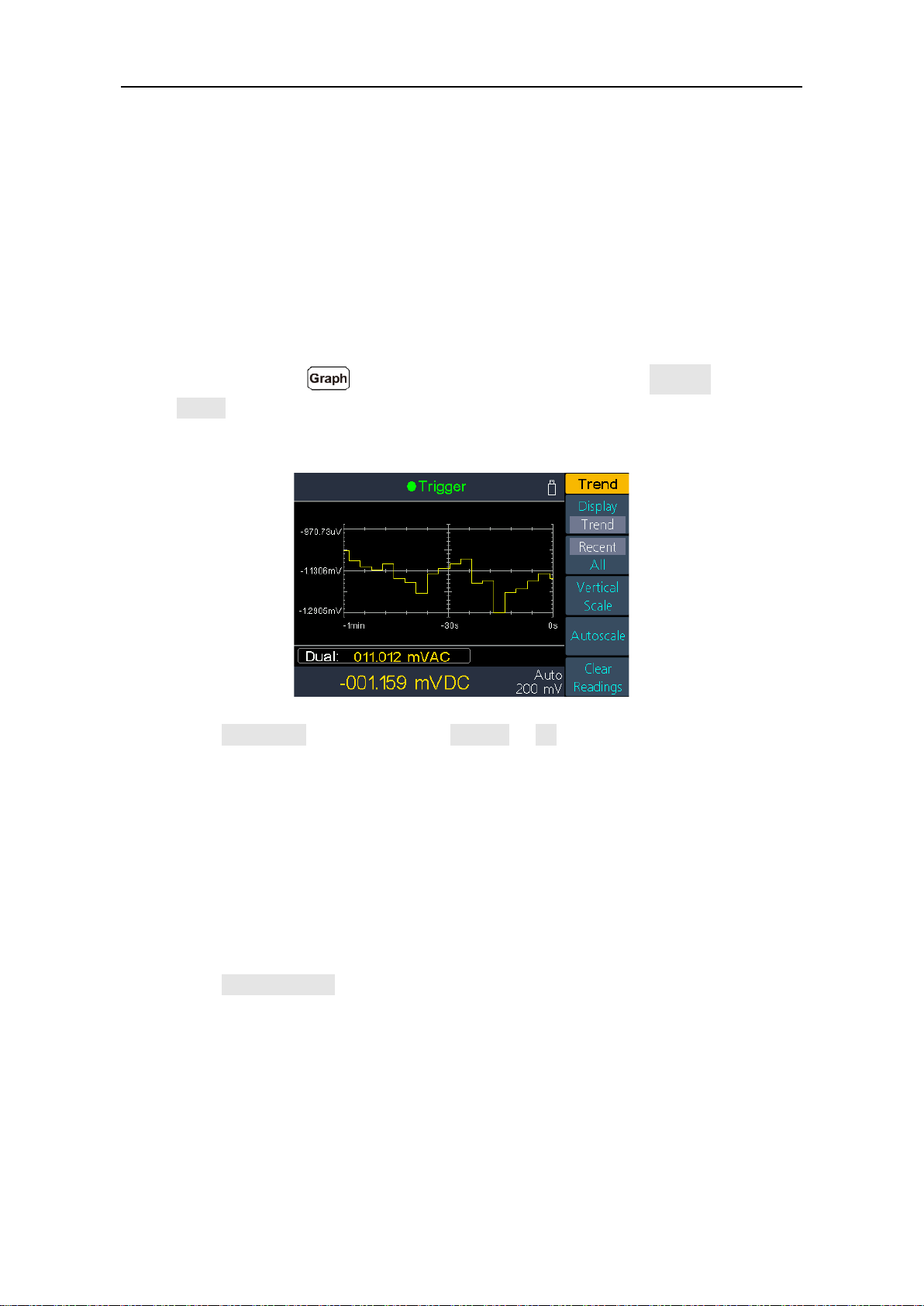
Trend Chart
Press the front panel key to access the menu, press the Display softkey to
select Trend. The trend chart shows data trends over time, users can directly
observe the variation of the measured data.
Press the Recent/All softkey to select Recent or All. In the trend chart, Recent
shows just the most recent data, All shows all of the data.
All: The trend chart displays all readings being taken and builds from left to
right. After the display is filled, the data becomes compressed on the left side of
the display as new data is added on the right side of the display.
Recent: The trend chart displays data taken during the last minute.
Press the Vertical Scale softkey to specifies how the current vertical scale is
determined.
Default: Set the scale to equal the measurement range. For example, for the
DCV measurement function, the vertical scale will be set as -200 mV to 200 mV
when the present range is 200 mV.
Manual: Allow you to configure the scale either as High and Low values or as a
Span around a Center value. For example, a scale that goes from a Low of -50
Page 47

43
mV to a High of 100 mV could also be specified as a Center of 25 mV with a
Span of 150 mV.
Auto: Automatically adjusts the scale to appropriately fit the line currently shown
on the screen.
Press the Autoscale softkey to automatically set the vertical scale once.
Press the Clear Readings softkey to clear reading memory and redraw.
Histogram
Press the front panel key to access the menu, press the Display softkey to
select Histogram. In the histogram display, data is grouped in bins represented by
vertical bars. The histogram shows the distribution of measurement data.
Press the Binning softkey to select Auto binning or Manual binning.
Press the Cumulative softkey to hide or show a line representing the cumulative
distribution of the histogram data.
Press the Clear Readings softkey to clear reading memory and redraw.
Auto binning
The algorithm starts by continuously readjusting the histogram span based on the
readings coming in, completely re-binning the data whenever a new value comes
in outside of the current span. The number of bins shown is a function of the
number of readings received:
Number of
readings
<100
100 -
500
500 1000
1000 -
5000
>5000
Number of bins
10
20
40
100
300
Total number of samples
Total number of bins
Percentage of samples in the largest bin
Number of samples in the largest bin
Page 48

44
Manual binning
Press the Bin Settings softkey to access the bin settings menu.
Press the Num.Bins softkey to set number of bins to 10, 20, 40, 100, or 300.
You can specify the bin range as either Low and High values, or as a Span
around a Center value. For example, the bin range with a Low of -5 V and a
High of 10 V could be specified as a Center of 2.5 V and a Span of 15 V.
Press the Outer Bins softkey to display or hide the outer bins. The outer bins are
two additional bins, for readings above and below the bin range.
Page 49

45
Data Record Function
Data record function includes manual record and auto record. You can use any or
both functions to record the data.
Manual record: Press the front panel key to save current reading to
internal memory. The maximum number of readings is 1000. Once you have
finished collecting data, you can view it in table, and export it to external memory.
Auto record: After setting memory, number of readings, sample interval, press
the Start softkey to start recording. You can view the data in internal memory in
table or graph.
Manual Record
1. Collect data: The instrument saves current reading in internal memory each
time the front panel key is pressed. The instrument beeps, and the
icon will show up on the top of the display.
Note: The measurement function can be switched during manual record.
When the dual display is enabled, both readings can be recorded.
2. View the manual record: Press the front panel key, press the
Manual record softkey to display the data table. Press keys to turn the
page. (When the data table is shown, you can still save current reading by
pressing the key.)
Note:
When the recording data exceeds the current range, the data will be marked
as "overload".
"rel" in the table indicates the relative operation is turned on.
Page 50

46
3. Export to USB memory: Connect a USB memory to the front panel USB
connector. Press the Export softkey to export the manual record in internal
memory to USB memory as a CSV file. The file will be saved in
\Record\Manual folder in USB memory. The file name is
Data_YYYYMMDD_HHMMSS, YYYYMMDD is the data recording start date,
HHMMSS is the start time, e.g. Data_20160804_095622.csv.
4. Clear the manual record: Press the Clear softkey to clear current manual
record.
Auto Record
1. Configure the parameters: Press the front panel key, press the Auto
record softkey.
Press the Memory softkey to select internal or external memory
Press the Points softkey to specify the total number of readings to record. The
range is 1 to 1 M for internal memory, 1 to 100 M for external memory.
Press the Interval softkey to specify the time interval between readings. The
range is 5 ms to 1000 s.
2. Record data: Press the Start softkey to start auto record. The icon will
show up on the top of the display. Press the Stop softkey to stop recording,
the data will be saved in the specified memory as a CSV file. If the external
memory is selected, the file will be saved in \Record\Auto folder in USB
memory. The file name is Data_YYYYMMDD_HHMMSS, YYYYMMDD is the
data recording start date, HHMMSS is the start time, e.g.
Data_20160804_095622.csv.
Note:
When the auto recording mode is running, press another measurement
function key, the instrument will display a message "Press the key again to
switch function and stop recording.".
If you want to continue auto recording, just wait until the message
disappears.
If you want to stop auto recording and switch to the function, press the
function key again when the message is still displayed. The recording data
before switching the function will be saved.
In auto range, the relay switch may cause jitter, the data at this time is
invalid. It will last about a few hundred milliseconds, and the data acquired in
this period will be marked as "invalid".
Page 51

47
When the dual display is enabled, only the reading of main display function
can be saved.
3. Read and view the auto recording file: Press the front panel key,
press the View record softkey.
Memory can only be internal memory.
Press the Display softkey to select Table or Graph to display the readings.
Press the Read softkey to read and view the auto record file in the internal
memory. (If the data is viewed in table, press keys to turn the page.)
Auto recording data displayed in graph
Auto recording data displayed in table
Page 52

48
Port Configuration
You can configure the port parameters in port configuration.
Serial
Press the front panel key, press the Serial softkey to access the serial port
setting menu.
Press the Baud softkey to select the desired baud rate from 1200, 2400, 4800,
9600, 19200, 38400, 57600 or 115200. The default is 9600. Make sure that the
baud rate matches that of the computer.
Press the Data bits softkey, select the data bits from 5, 6, 7, 8.
Press the Odd-Even softkey, select the parity from None, Odd or Even. The
default is None.
Press the Stop bit softkey, select the stop bit from 1, 2.
Trigger
See page 36, Triggering.
Output
Press the front panel key, press the Output softkey to access the output
setting menu.
Press the Output softkey to configure the output of the [AUX Output] connector at
the rear panel.
VMComp
Defaults to Voltmeter Measurement Complete Output, outputs a pulse whenever
the multimeter finishes taking a measurement to allow you to signal other devices.
Press the VMC Out softkey to set the edge slope of the voltmeter complete
output.
P/F
The [AUX Output] connector can be configured to output a pulse when the limits
are exceeded in Math limits function.
Page 53

49
Net Type
Press the front panel key, press the NET Type softkey to select Off, LAN
etc.
LAN
Press the LAN Setting softkey, set the IP address, subnet mask, gateway, port.
Press to move the cursor, press to increase or decrease the value.
Restart the instrument for the parameter changes to take effect.
Contact your LAN administrator for the LAN setting details.
Utility Menu
You can set the parameters of the system-related functions. in utility menu.
Language
Press the front panel key, press the Language softkey to switch display
languages.
Backlight
Press the front panel key, press the BLight softkey to adjust the
brightness.
Clock
Press the front panel key, press the Clock softkey. The clock menu
displays the date and time. The time always uses a 24-hour format (00:00:00 to
23:59:59).
Press the Setup softkey to edit the date and time, press to move the cursor,
press to increase or decrease the value. Press the Done softkey to finish
the clock setting.
SCPI
Press the front panel key, press the SCPI softkey to select the desired
setting.
Default
Press → Next → Default to restore the multimeter to factory defaults. The
measurement function will be automatically set to DCV.
Page 54

50
Factory default settings
Parameter
Factory Setting
Measurement
DCV
Range
Auto
Speed
Low
Filter
Off
Input Z
10M
Rel
Off
ACV
Range
Auto
Speed
Low
Rel
Off
DCI
Range
Auto
Speed
Low
Filter
Off
Rel
Off
ACI
Range
Auto
Speed
Low
Rel
Off
Ω2W/Ω4W
Range
Auto
Speed
Low
Ω 2W/Ω 4W
Ω 2W
Rel
Off
Cont
Beeper
On
Page 55

51
Parameter
Factory Setting
Threshold
50Ω
Diode
Beeper
On
CAP
Range
Auto
Rel
Off
Freq
Range
Auto
Freq/Period
Freq
Rel
Off
Temp
Load
KITS90
Display
All
Units
K
Rel
Off
Math
Statistics
Show/Hide
Hide
Limits
Limits
Off
High
2V/2A/2KΩ/2uF/2Hz/2s/2k
℃
Low
0V/0A/0KΩ/0uF/0Hz/0s/0k
℃
Center
1V/1A/1KΩ/1uF/1Hz/1s/1k
℃
Span
2V/2A/2KΩ/2uF/2Hz/2s/2k
℃
Pass/Fail
Pass
dB/dBm
On/Off
Off
Function
dBm
Ref R
50Ω
Page 56

52
Parameter
Factory Setting
dB Ref Value
0 dBm
Rel
0 V
Beeper
On
Utility
BLight
50%
SCPI
8845
Port
Serial
Baud
115200
Data bits
8
Odd-Even
None
Stop bit
1
Trigger
Source
Auto
Delay
Auto
Delay time
0 s
Samples
trigger
1
Output
Output
VM Comp
VMC Out
Positive
NET Type
IP
192.168.001.099
Subnet Mask
255.255.255.000
Gateway
192.168.001.001
Physical
address
000fea36ea46
Port
3000
Net
Off
Graph
Display
Number
Page 57

53
Parameter
Factory Setting
Bar Meter
Scale
Default
Trend
Recent/All
Recent
Histogram
Binning
Auto
Cumulative
Off
Record
Auto
record
Memory
Internal
Points
1000
Interval
1 s
Start/Stop
Stop
View
record
Display
Graph
System Info
Press → Next → System Info to view the model, firmware version, serial
number.
Update firmware
Use the front-panel USB port to update your instrument firmware using a USB
memory device.
USB memory device requirements: This instrument supports a USB memory
device with a FAT32 or FAT16 file system. If the USB memory device doesn't
work properly, format it into the FAT32 or FAT16 format and try again; or try
another USB memory device.
Caution: Updating your instrument firmware is a sensitive operation, to
prevent damage to the instrument, do not power off the
instrument or remove the USB memory device during the
update process.
To update your instrument firmware, do the following:
1. Press → Next → System Info to view the model and firmware version.
Page 58

54
2. From a PC, visit www.PeakTech.de and check if the website offers a newer
firmware version. Download the firmware file. The file name must be
DMMFW.upp. Copy the firmware file onto the root directory of your USB
memory device.
3. Insert the USB memory device into the front-panel USB port on your
instrument. If the icon appears on the top right of the screen, the USB
memory device is installed successfully.
4. Press → Next → System Info, press the Update firmware softkey.
5. The instrument displays a message telling you not to remove the USB device
or power off the instrument until the update process is complete. The progress
bar of the screen indicates the update process is in progress.
Note: A firmware update usually takes approximately a minute. Do not remove
the USB memory device during the update process. If you accidentally
removed the USB memory device during the update process, do not power off
the instrument. Repeat the installation process from step 3.
6. Wait until the instrument displays "Firmware upgrade success.", and then it
will reboot automatically.
Note: If the operation complete message is not displayed, do not power off the
instrument. Repeat the installation process from step 2 using a different type of
USB memory device.
7. Remove the USB memory device from the front-panel USB connector.
8. Press → Next → System Info, view the firmware version. Confirm that
the firmware has been updated.
LCD Test
The instrument provides the screen self testing, which can test the LCD screen.
Press → Next → LCD Test to access the screen test interface. Press the
Change softkey to switch the color between red, green, and blue. Observe if the
screen has severe color shift, spot, scuffing, or other defect. Press the last softkey
to exit the test.
Key Test
The instrument provides the key self testing, which can test the keys on the front
panel.
Page 59

55
Press → Next → Key Test to access the key test interface. Each shape on
the test interface represents a front panel key. Press any front panel key, the
corresponding shape on the test interface will turn green. Press the Return
softkey to exit the test.
Page 60
56
4. Measurement Tutorial
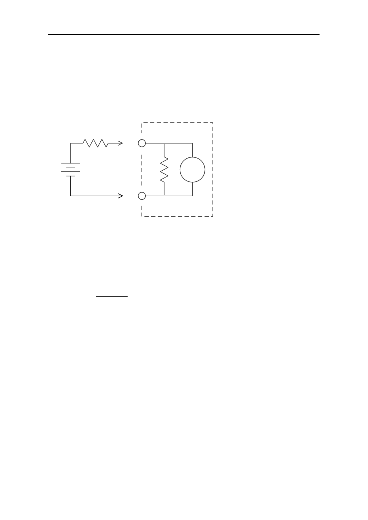
Loading Errors (DC Voltage)
Measurement loading errors occur when the resistance of the DUT(Device-UnderTest) is an appreciable percentage of the multimeter's input resistance, as shown
below.
Vs = ideal DUT voltage
Rs = DUT source resistance
Ri = multimeter input resistance (10 MΩ or >10 GΩ)
Error
is
s
100 R
()
RR
%
To reduce the effects of loading errors and to minimize noise interference, set the
multimeter's input resistance to 10 GΩ for the 200 mVDC and 2 VDC ranges. The
input resistance is maintained at 10 MΩ for the 20 VDC, 200 VDC, and 1000 VDC
ranges.
HI
LO
Ideal
Meter
R
s
V
s
R
i
Page 61

57
True RMS AC Measurements
The AC measurement of the multimeter has true RMS response. Power
dissipated in a resistor is proportional to the square of an applied voltage,
independent of the wave shape of the signal. This multimeter accurately
measures true rms voltage or current, as long as the wave shape contains
negligible energy above the meter’s effective bandwidth.
The effective AC voltage bandwidth of the multimeter is 100 kHz, while the
effective AC current bandwidth is 10 kHz.
Waveform
Shape
Crest Factor
(C.F.)
AC RMS
AC+DC RMS
2
V
2
V
2
3
V
3
V
3
(50% duty cycle)
1
V
C.F.
V
C.F.
The multimeter's AC voltage and AC current functions measure the AC-coupled
true rms value, the RMS value of only the AC components of the input waveform
are measured (DC is rejected). As seen in the figure above; for sine waves,
triangle waves, and square waves, the AC–coupled and AC+DC values are equal,
because these waveforms do not contain a DC offset. However, for non–
symmetrical waveforms (such as pulse trains) there is a DC voltage content,
which is rejected by the multimeter’s AC–coupled true rms measurements.
The AC coupled true RMS measurement is especially useful for measuring small
AC signals in the presence of large DC offsets. For example, this situation is
common when measuring AC ripple present on DC power supplies. However,
there are situations where you might want to know the AC+DC true RMS value.
You can determine this value by combining results from DC and AC
measurements, as shown below:
0V0
V
0
V
t
T
Page 62

58
22
ac dc ac dc
For the best AC noise rejection, you should select "Low" measurement speed to
get 5½ digits reading resolution when performing the DC measurement.
Page 63

59
Loading Errors (AC Voltage)
In the AC voltage function, the input impedance of the multimeter appears as a 1
MΩ resistance in parallel with 100 pF of capacitance. The cabling that you use to
connect signals to the multimeter also adds capacitance and loading. The table
below shows the multimeter's approximate input resistance at various
frequencies.
Input Frequency
Input Resistance
100 Hz
1 MΩ
1 kHz
850 kΩ
10 kHz
160 kΩ
100 kHz
16 kΩ
For low frequencies, the loading error is:
Error
s
s
100 R
(%
1
)
RM
At high frequencies, the additional loading error is:
Error
2
S in
1
(%) 100
2
1
1 F R C
Rs = source resistance
F = input frequency
Cin = input capacitance (100 pF) plus cable capacitance
Page 64

60
5. Troubleshooting
1. The instrument is powered on but no Display.
1) Check if the power is connected properly.
2) Check if the AC Mains Line Voltage Selector is in the proper voltage scale.
3) Check if the line fuse which is below the AC Mains Input is used
appropriately and in good condition (see page 69, Appendix C: Line Fuse
Replacement).
4) Restart the instrument after the steps above.
5) If the problem still exists, please contact PEAKTECH for our service.
2. The reading does not change when a current signal is input.
1) Check whether the test lead is correctly inserted into the current input
terminals (I terminal and LO Input terminal).
2) Check whether the current terminal fuse at the front panel is burned out.
Please refer to "7 Current Terminal Fuse" in "Front panel overview" on page
9.
3) Check whether the DCI or ACI measurement function is enabled.
4) Check whether the DCI measurement function is used to measure AC
current.
If you encounter other problems, try to reset the settings or restart the instrument.
If it still can not work properly, please contact PEAKTECH for our service, and
provide your device information. ( → Next → System Info)
Page 65

61
6. Technical Specifications
P4096 Specifications
Accuracy: ± (% of reading + % of range)
[1]
Function
Range
[2]
Frequency Range
or Test Current
Accuracy:
1 year
23℃±5℃
Temperature
Coefficient
0℃ - 18℃
28℃ - 50℃
DC Voltage
200 mV
/
0.015±0.004
0.0015 + 0.0005
2 V
0.0010 + 0.0005
20 V
0.0020 + 0.0005
200 V
0.0015 + 0.0005
1000 V
[3]
0.0015 + 0.0005
True RMS
AC Voltage
[4]
200mV, 2V, 20V, 200V, 750V
20 Hz – 45 Hz
1.5 + 0.10
0.01 + 0.005
45 Hz – 20 kHz
0.2 + 0.05
0.01 + 0.005
20 kHz – 50 kHz
1.0 + 0.05
0.01 + 0.005
50 kHz – 100 kHz
3.0 + 0.05
0.05 + 0.010
DC Current
200.000 μA
/
0.055 + 0.005
0.003 + 0.001
2.00000 mA
0.055 + 0.005
0.002 + 0.001
20.0000 mA
0.095 + 0.020
0.008 + 0.001
200.000 mA
0.070 + 0.008
0.005 + 0.001
2.00000 A
0.170 + 0.020
0.013 + 0.001
10.0000 A
[5]
0.250 + 0.010
0.008 + 0.001
True RMS
AC Current
[6]
20.0000 mA, 200.000 mA,
2.00000 A, 10.0000 A
[5]
20 Hz – 45 Hz
1.5 + 0.10
0.015 + 0.005
45 Hz – 2 kHz
0.50 + 0.10
0.015 + 0.005
2 kHz – 10 kHz
2.50 + 0.20
0.015 + 0.005
Resistance
[7]
200.000 Ω
1 mA
0.030 + 0.005
0.0030 + 0.0006
2.00000 kΩ
1 mA
0.020 + 0.003
0.0030 + 0.0005
20.0000 kΩ
100 μA
0.020 + 0.003
0.0030 + 0.0005
200.000 kΩ
10 μA
0.020 + 0.003
0.0030 + 0.0005
2.00000 MΩ
1 μA
0.040 + 0.004
0.0040 + 0.0005
10.0000 MΩ
200 nA
0.250 + 0.003
0.0100 + 0.0005
100.000 MΩ
200 nA || 10 MΩ
1.75 + 0.004
0.2000 + 0.0005
Diode Test
2.0000 V
[8]
1 mA
0.05 + 0.01
0.0050 + 0.0005
Continuity
2000 Ω
1 mA
0.05 + 0.01
0.0050 + 0.0005
Frequency
200 mV to 750 V
[9]
20 Hz – 2 kHz
0.01 + 0.003
0.002 + 0.001
Page 66

62
/Period
2 kHz – 20 kHz
0.01 + 0.003
0.002 + 0.001
20 kHz – 200 kHz
0.01 + 0.003
0.002 + 0.001
200 kHz – 1 MHz
0.01 + 0.006
0.002 + 0.002
20 mA to 10 A
20 Hz – 2 kHz
0.01 + 0.003
0.002 + 0.001
2 kHz – 10 kHz
0.01 + 0.003
0.002 + 0.001
Capacitance
[10]
2.000 nF
200 nA
3 + 1.0
0.08 + 0.002
20.00 nF
200 nA
1 + 0.5
0.02 + 0.001
200.0 nF
2 μA
1 + 0.5
0.02 + 0.001
2.000 μF
10 μA
1 + 0.5
0.02 + 0.001
200 μF
100 μA
1 + 0.5
0.02 + 0.001
10000 μF
1 mA
2 + 0.5
0.02 + 0.001
Temperature
Temperature sensors under 2 categories supported thermocouple (ITS-90 conversion between B / E / J / K / N / R / S / T type), and thermal
resistance (RTD sensor conversion between PT100 and PT385 type)
[1]
Specifications are for 30-minute warm-up, "Low" measurement rate and calibration temperature
18℃ - 28℃.
[2] 20% over range on all ranges, except 1,000 V DCV, 750 ACV, 10 A DCI, 10 A ACI, 100 MΩ resistance,
and 10000 μF capacitance.
[3] For each additional volt over ± 500 VDC add 0.02 mV of error.
[4] Specifications are for amplitude of sine wave input > 0.5% of range. For inputs from 1% to 5% of range
and <50 kHz, add 0.1% of range extra error. For 50 kHz to 100 kHz, add 0.13% of range extra error.
[5] 30 seconds OFF after 30 seconds ON is recommend for the continuous current that higher than DC 7 A or
AC RMS 7 A.
[6] Specifications are for amplitude of sine wave input > 0.5% of range. 0.1% errors will be added when the
range of input sine wave is 1% to 5%.
[7] Specifications are for 4–wire ohms function or 2–wire ohms using the relative operation of math. Without
relative operation, add ±0.20 Ω additional error in 2-wire ohms function.
[8] Specifications are for the voltage measured at the input terminals. The 1 mA test current is typical.
Variation in the current source will create some variation in the voltage drop across a diode junction.
[9] Except for special marks, the AC input voltage is 15% to 120% of range when ≤100 kHz and 30% to 120%
of range when >100 kHz. 750 V range is limited to 750 Vrms.
[10]Specifications are for using the relative operation of math. Using of non-film capacitor may generate
additional errors. Specifications are for from 1% to 120% on 2 nF range and ranges from 10% to 120% on
other ranges.
Page 67

63
P4095 Specifications
Accuracy: ± (% of reading + % of range)
[1]
Function
Range
[2]
Frequency Range
or Test Current
Accuracy:
1 year
23℃±5℃
DC Voltage
600 mV
/
0.02±0.01
6 V
60 V
600 V
1000 V
[3]
True RMS
AC Voltage
[4]
600mV, 6V, 60V, 600V, 750V
20 Hz – 45 Hz
2 + 0.10
45 Hz – 20 kHz
0.2 + 0.06
20 kHz – 50 kHz
1.0 + 0.06
50 kHz – 100 kHz
3.0 + 0.08
DC Current
600.00 μA
/
0.06 + 0.02
6.0000 mA
0.06 + 0.02
60.000 mA
0.1 + 0.05
600.00 mA
0.2 + 0.02
6.0000 A
0.2 + 0.05
10.000 A
[5]
0.250 + 0.05
True RMS
AC Current
[6]
60.000 mA, 600.00 mA,
6.0000 A, 10.000 A
[5]
20 Hz – 45 Hz
2 + 0.10
45 Hz – 2 kHz
0.50 + 0.10
2 kHz – 10 kHz
2.50 + 0.20
Resistance
[7]
600.00 Ω
1 mA
0.040 + 0.01
6.0000 kΩ
1 mA
0.030 + 0.01
60.000 kΩ
100 μA
0.030 + 0.01
600.00 kΩ
10 μA
0.040 + 0.01
6.0000 MΩ
1 μA
0.120 + 0.03
60.000 MΩ
200 nA || 10 MΩ
0.90 + 0.03
100.00 MΩ
200 nA || 10 MΩ
1.75 + 0.03
Diode Test
3.0000 V
[8]
1 mA
0.05 + 0.01
Continuity
1000 Ω
1 mA
0.05 + 0.01
Frequency
/Period
600 mV to 750 V
[9]
20 Hz – 2 kHz
0.01 + 0.003
2 kHz – 20 kHz
0.01 + 0.003
20 kHz – 200 kHz
0.01 + 0.003
Page 68

64
200 kHz – 1 MHz
0.01 + 0.006
60 mA to 10 A
20 Hz – 2 kHz
0.01 + 0.003
2 kHz – 10 kHz
0.01 + 0.003
Capacitance
[10]
2.000 nF
200 nA
3 + 1.0
20.00 nF
200 nA
1 + 0.5
200.0 nF
2 μA
1 + 0.5
2.000 μF
10 μA
1 + 0.5
200 μF
100 μA
1 + 0.5
10000 μF
1 mA
2 + 0.5
Temperature
Temperature sensors under 2 categories supported thermocouple (ITS-90 conversion between B / E / J / K / N / R / S / T type), and thermal
resistance (RTD sensor conversion between PT100 and PT385 type)
[1]
Specifications are for 30-minute warm-up, "Low" measurement rate and calibration temperature
18℃ - 28℃.
[2] 10% over range on all ranges, except 1,000 V DCV, 750 ACV, 10 A DCI, 10 A ACI, 100 MΩ resistance,
and 10000 μF capacitance.
[3] For each additional volt over ± 500 VDC add 0.02 mV of error.
[4] Specifications are for amplitude of sine wave input > 0.5% of range. For inputs from 1% to 5% of range
and <50 kHz, add 0.1% of range extra error. For 50 kHz to 100 kHz, add 0.13% of range extra error.
[5] 30 seconds OFF after 30 seconds ON is recommend for the continuous current that higher than DC 7 A or
AC RMS 7 A.
[6] Specifications are for amplitude of sine wave input > 0.5% of range. 0.1% errors will be added when the
range of input sine wave is 1% to 5%.
[7] Specifications are for 4–wire ohms function or 2–wire ohms using the relative operation of math. Without
relative operation, add ±0.20 Ω additional error in 2-wire ohms function.
[8] Specifications are for the voltage measured at the input terminals. The 1 mA test current is typical.
Variation in the current source will create some variation in the voltage drop across a diode junction.
[9] Except for special marks, the AC input voltage is 15% to 110% of range when ≤100 kHz, and 30% to
110% of range when >100 kHz. 750 V range is limited to 750 Vrms. When the measurement range of AC
voltage is in 600 mV range, multiply % of reading error x10.
[10]Specifications are for using the relative operation of math. Using of non-film capacitor may generate
additional errors. Specifications are for from 1% to 110% on 2 nF range and ranges from 10% to 110% on
other ranges.
Page 69

65
P4094 Specifications
Function
Range
[2]
Resolution
Accuracy: ± (% of reading + digits)
[1]
DC Voltage
50.000 mV
0.001 mV
0.1% + 10
500.00 mV
0.01 mV
0.025% + 5
5.0000 V
0.0001 V
0.025% + 5
50.000 V
0.001 V
0.03% + 5
500.00 V
0.01 V
0.1% + 5
1000.0 V
[3]
0.1 V
0.1% + 5
True RMS
AC Voltage
[4]
500 mV – 750 V
20 Hz – 45 Hz
1% + 30
45 Hz – 65 Hz
0.5% + 30
65 Hz – 1 kHz
0.7% + 30
DC Current
500 uA
0.01 uA
0.15% + 20
5000 uA
0.1 uA
0.15% + 10
50 mA
0.001 mA
0.15% + 20
500 mA
0.01 mA
0.15% + 10
5 A
0.0001 A
0.5% + 10
10 A
[5]
0.001 A
0.5% + 10
True RMS
AC Current
[6]
500 uA – 500 mA / 0.5% + 20
5 A – 10 A
1.5% + 20
Resistance
[7]
500 Ω
0.01 Ω
0.1% + 10
5 kΩ
0.0001 kΩ
0.1% + 5
50 kΩ
0.001 kΩ
0.1% + 5
500 kΩ
0.01 kΩ
0.1% + 5
Page 70

66
5 MΩ
0.0001 MΩ
0.25% + 5
50 MΩ
0.001 MΩ
1% + 10
Four-wire
Resistance
500 Ω
0.01 Ω
0.1% + 10
5 kΩ
0.0001 kΩ
0.1% + 5
50 kΩ
0.001 kΩ
0.1% + 5
Diode
3.0000 V
0.0001 V
/
Continuity
1000 Ω
0.1 Ω
/
Frequency
10.000 Hz – 60 MHz
[8]
/
± (0.2% + 8)
Capacitance
[9]
50 nF – 500 uF / 2.5% + 5
5 mF – 50 mF
5% + 8
Temperature
K type, PT100
Display
55,000
Record Interval
15 mS – 9999.999 S
[1]
Specifications are for 30-minute warm-up, "Low" measurement rate and calibration temperature
18℃ - 28℃.
[2] 10% over range on all ranges, except 1,000 V DCV, 750 ACV, 10 A DCI, 10 A ACI, 100 MΩ resistance,
and 10000 μF capacitance.
[3] For each additional volt over ± 500 VDC add 0.02 mV of error.
[4] Specifications are for amplitude of sine wave input > 0.5% of range. For inputs from 1% to 5% of range
and <50 kHz, add 0.1% of range extra error. For 50 kHz to 100 kHz, add 0.13% of range extra error.
[5] 30 seconds OFF after 30 seconds ON is recommend for the continuous current that higher than DC 7 A or
AC RMS 7 A.
[6] Specifications are for amplitude of sine wave input > 0.5% of range. 0.1% errors will be added when the
range of input sine wave is 1% to 5%.
[7] Specifications are for 4–wire ohms function or 2–wire ohms using the relative operation of math. Without
relative operation, add ±0.20 Ω additional error in 2-wire ohms function.
[8] Specifications are for the voltage measured at the input terminals. The 1 mA test current is typical.
Variation in the current source will create some variation in the voltage drop across a diode junction.
[9] Except for special marks, the AC input voltage is 15% to 110% of range when ≤100 kHz, and 30% to
110% of range when >100 kHz. 750 V range is limited to 750 Vrms. When the measurement range of AC
voltage is in 600 mV range, multiply % of reading error x10.
[10]Specifications are for using the relative operation of math. Using of non-film capacitor may generate
additional errors. Specifications are for from 1% to 110% on 2 nF range and ranges from 10% to 110% on
other ranges.
Temperature Characteristic
Page 71

67
Accuracy: ± (% of reading + % of range)
[1]
Function
Probe
Type
Probe Model
Working Temperature
Range
Accuracy:
1 year
23℃±5℃
Temperature
Coefficient
0℃ - 18℃
28℃ - 50℃
Temperature
RTD
[2]
α=0.00385
-200℃ to 660℃
0.16℃
0.08+0.002
TC
[3]
B
0℃ to 1820℃
0.76℃
0.14℃
E
-270℃ to 1000℃
0.5℃
0.02℃
J
-210℃ to 1200℃
0.5℃
0.02℃
K
-270℃ to 1372℃
0.5℃
0.03℃ N
-270℃ to 1300℃
0.5℃
0.04℃
R
-270℃ to 1768℃
0.5℃
0.09℃
S
-270℃ to 1768℃
0.6℃
0.11℃
T
-270℃ to 400℃
0.5℃
0.03℃
[1] Specification are for 0.5 hour warm-up, not include probe error.
[2] Specification are for 2-wire measure under "REF" operation.
[3] Built-in cold terminal compensation for thermocouple, accuracy is ±2℃.
Data Record Function
Manual Record Function
Press the front panel Save key to save current reading. The maximum number of readings is 1000.
Auto Record Function
Max number of readings
1 M for internal memory; 100 M for external memory
Max storage capacity
8 MB for internal memory; 800 MB for external memory
Sample interval
5 ms to 1000 s
Trigger
External Trigger
Input
Input level
TTL compatible (High level when left input terminal is
hanging in the air)
Trigger condition
Selectable rising edge or falling edge
Input impedance
≥20 kΩ in parallel with 400 pF, DC-coupled
Minimum pulse width
500 μs
VMC Output
Level
TTL compatible
Output polarity
Selectable positive or negative
Output impedance
200 Ω, typical
General Specifications
Dimension
(W x H x D): 235 mm × 110 mm × 295 mm
Weight
3.06 kg
Page 72

68
7. Appendix
Appendix A: Enclosure
Standard Accessories (subject to final delivery):
Power Cord
Test lead
Alligator clip
USB Cable
Spare Fuses
10A, 250 VAC
Software / Driver /
Manual
Appendix B: General Care and Cleaning
General Care
Do not store or leave the instrument where the liquid crystal display will be
exposed to direct sunlight for long periods of time.
Cleaning
To clean the instrument exterior, perform the following steps:
1. To prevent electrical shock, disconnect the instrument from AC mains
power and disconnect all test leads before cleaning.
2. Clean the outside of the instrument using a wet soft cloth not dripping
water. Do not make any scuffing when cleaning the LCD screen. To avoid
damage to the instrument, do not use any corrosive chemical cleaning
agent.
Caution: To avoid any damage to the instrument, do not exposed it to any
sprays, liquids, or solvents.
Page 73

69
Warning: Before power on again for operation, it is required to confirm
that the instrument has already been dried completely,
avoiding any electrical short circuit or bodily injury resulting
form the moisture.
Appendix C: Line Fuse Replacement
The line fuse is in the plastic fuse box below the power line input on the rear
panel.
Warning: Disconnect the line cord at the rear panel and remove all test
leads connected to the instrument before replacing the line
fuse. Failure to do so could expose the operator to hazardous
voltages that could result in personal injury or death.
Use only the correct fuse type. Failure to do so could result in personal injury or
instrument damage.
Voltage
Fuse
100 - 120 V AC
250 V, F1AL
220 - 240 V AC
250 V, F0.5AL
To perform the line fuse replacement, follow these steps:
1. Turn off the multimeter, remove all measurement leads and other cables from
the instrument, including the power cord.
2. Use a flat-blade screwdriver to remove the fuse box.
3. Replace the fuse with a new one, which should match with the voltage; install
it into the fuse box, and push the fuse box back on to the rear panel.
Page 74

70
All rights, also for translation, reprinting and copy of this manual or parts are
reserved.
Reproduction of all kinds (photocopy, microfilm or other) only by written permission
of the publisher.
This manual considers the latest technical knowing. Technical changings which are
in the interest of progress reserved.
We herewith confirm, that the units are calibrated by the factory according to the
specifications as per the technical specifications.
We recommend to calibrate the unit again, after 1 year.
PeakTech® 10/2021 Ehr./Lie/Ehr.
PeakTech Prüf- und Messtechnik GmbH
– Gerstenstieg 4 - DE-22926 Ahrensburg / Germany
+49 (0) 4102 97398-80 +49 (0) 4102 97398-99
info@peaktech.de www.peaktech.de
 Loading...