

Page 1

DDS Arbitrary
Waveform Generator
Operation manual
PeakTech
®
4046
Page 2

1. Safety Precautions
This product complies with the requirements of the following European Community
Directives: 2014/130/EU (Electromagnetic Compatibility) and 2013/35/EU (Low Voltage)
as amended by 2014/32/EU (CE-Marking).
Overvoltage category II; pollution degree 2.
To ensure safe operation of the equipment and eliminate the danger of serious injury due
to short-circuits (arcing), the following safety precautions must be observed.
Damages resulting from failure to observe these safety precautions are exempt from any
legal claims whatever.
* The instrument must be set up so that the power plug can be removed from the
socket easily.
* Prior to connection of the equipment to the mains outlet, check that the available
mains voltage corresponds to the voltage setting of the equipment.
* Connect the mains plug of the equipment only to a mains outlet with earth connection.
* Do not place the equipment on damp or wet surfaces.
* Do not cover the ventilation slots of the cabinet to ensure that the air is able to
circulate freely inside.
* Do not insert metal objects into the equipment by way of the ventilation slots.
* Do not place water filled containers on the equipment (danger of short-circuit in case
of knock over of the container).
* Do not exceed the maximum permissible input ratings (danger of serious injury and/or
destruction of the equipment).
* To avoid electric shock, disconnect power to the unit under test and discharge all
capacitors before taking any resistance measurements.
* Check test leads and probes for faulty insulation or bare wires before connection to
the equipment.
* To avoid electric shock, do not operate this product in wet or damp conditions.
Conduct measuring works only in dry clothing and rubber shoes, i. e. on isolating
mats.
* Comply with the warning labels and other info on the equipment.
* The measurement instrument is not to be to operated unattended.
* Do not subject the equipment to direct sunlight or extreme temperatures, humidity or
dampness.
2
Page 3

* Do not subject the equipment to shocks or strong vibrations.
* Do not operate the equipment near strong magnetic fields (motors, transformers etc.)
* Keep hot soldering irons or guns away from the equipment.
* Allow the equipment to stabilize at room temperature before taking up measurement
(important for exact measurements).
* Do not input values over the maximum range of each measurement to avoid
damages of the meter.
* Use caution when working with voltages above 35V DC or 25V AC. These Voltages
pose shock hazard.
* Periodically wipe the cabinet with a damp cloth and mid detergent. Do not use
abrasives or solvents.
* The meter is suitable for indoor use only
* Do not operate the meter before the cabinet has been closed and screwed safely as
terminal can carry voltage.
* Do not store the meter in a place of explosive, inflammable substances.
* Do not modify the equipment in any way
* Do not place the equipment face-down on any table or work bench to prevent
damaging the controls at the front.
* Opening the equipment and service – and repair work must only be performed by
qualified service personnel
* -Measuring instruments don’t belong to children hands-
Cleaning the cabinet
Prior to cleaning the cabinet, withdraw the mains plug from the power outlet.
Clean only with a damp, soft cloth and a commercially available mild household cleanser.
Ensure that no water gets inside the equipment to prevent possible shorts and damage
to the equipment.
3
Page 4

2. Quick Start
If it’s the first time for y ou to use the generator or you have no time to read the
guide carefully, you can get the basic operation as soon as you finish browsing
the chapter1. If more complicated functions are needed or meet difficulties in
operation, please read Features and Functions in chapter 3.
2.1 Prepare the waveform generator for use
2.1.1 Check the list of supplied items
Verify that you have received the complete unit according to the packing list. If
you find package damaged badly, leave it until the instrument passes
performance test. If anything is missing, please contact sales office
2.1.2 Connect the power
Turn on the instrument only the following conditions are met,
Power: AC 100 ~ 240 V
Frequency: 45 ~ 65 Hz
Power consumption: < 30VA
Temperature: 0 ~ 40°C Humidity: <80%
Plug the power cord into an AC100 ~240V socket with ground wire and press On
/Off switch below socket on rear panel. Then blinking power button on front
panel indicating the generator well connected with power but still in off state.
Only press power button, the generator initializes itself and obtains the default
parameters, outputting continuous Sine under normal working state, with
signal’s parameters displayed.
4
Page 5

Warning: In order to ensure the security of the operator, use triple- core power
socket with ground wire.
5
Page 6

3. Front/Rear panels at a Glance
Front panel
1. Display 2. Function Keys 3. Numeric Keypad 4. Knob 5. On/Off Switch
6. Menu Operation Softkey 7. CHA/CHB Output 8. Sync Connector
9. USB Port 10. Arrow Keys
6
Page 7

Rear panel
1. Counter 2. External Clock Input 3. Internal Clock Input
4. Modulate Input / Trig Input / Output of CHB
5. Modulate Input / Trig Input / Output of CHA
6. LAN port 7. Fan 8. Power Socket
9. On/Off Swtich 10. USB Device
7
Page 8
4.1 Reference
4.1.1 Keypad description
There are totally 32 keys in the front panel, of which, 26 keys with certain definition
embraced with【】.
10 function keys:
【Continue】【 Modulate】【 Sweep】【 Burst】【 Dual Channel】【 Counter】【 CHA/CHB】
【Waveform】【Utility】【Output】.
While, 【Utility】key is used to set common parameter and 【Output】key is used to enable
or disenable output port.
12 keys in numeric keypad:
【0】【1】【2】【3】【4】【5】【6】【7】【8】【9】are used to enter numbers.
【.】is used to enter decimal point and 【-】is only available to enter allowed minus.
Four arrow keys:
【<】【>】were used to move the cursor left or right.
【∧ 】【∨ 】were used to increase and decrease the displayed number when setting
frequency and amplitude.
The balance 6 keys under display are menu operation softkeys, embraced with 〖〗 and
used to select menu or unit.
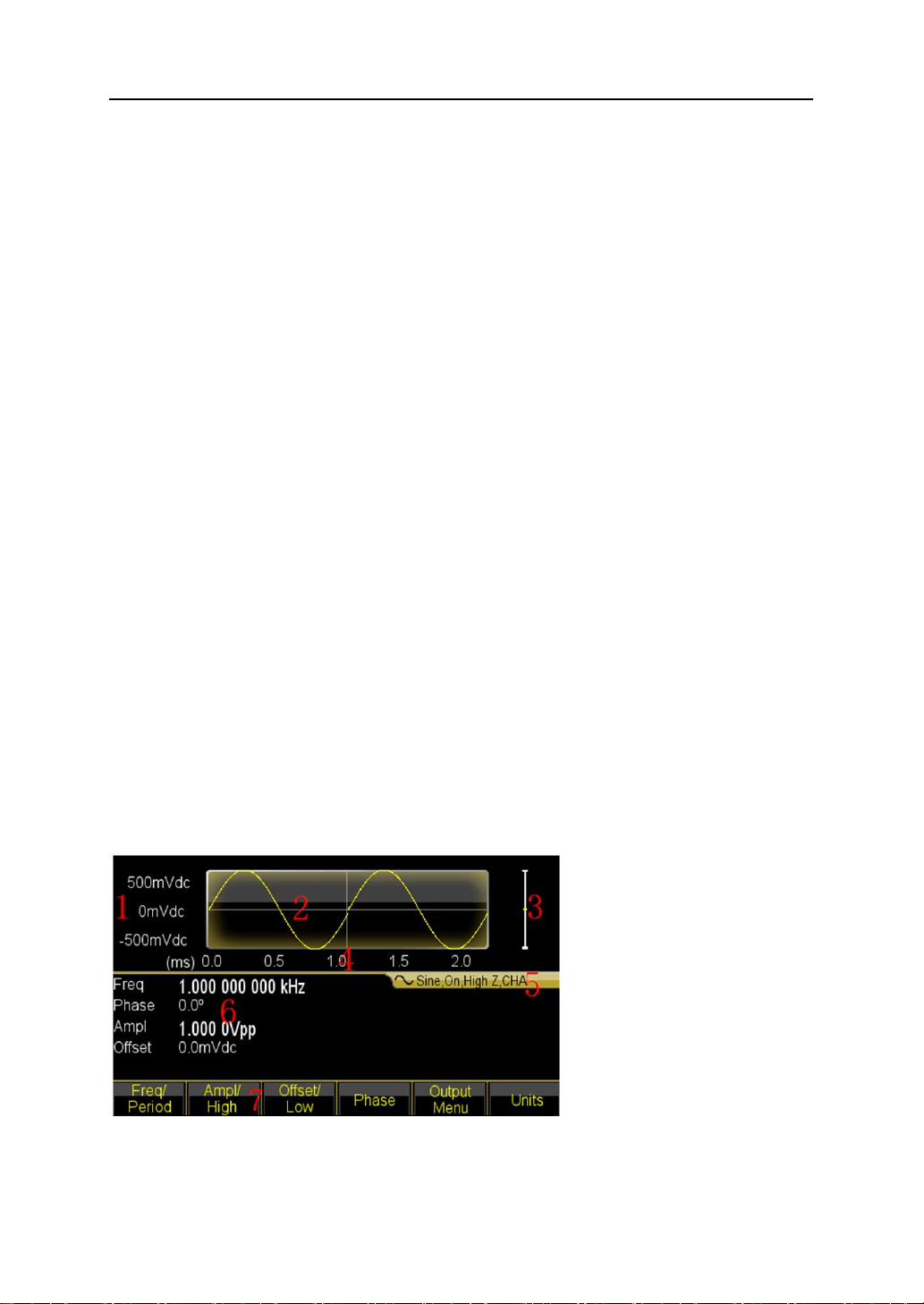
4.1.2 Display description
The display screen is divided into three sections:
Top section: output waveform
Middle section: parameters display of Frequency or Amplitude or Offset etc.
Bottom section: display of menu or unit.
8
Page 9

1. Voltage Scale 2.Waveform 3. Amplitude 4. Time Scale
5. Output Information 6. Working Parameters 7. Operation Menu
4.2 Number Entry
4.2.1 Use the keypad to enter numbers and softkey to select unit.
Please use 【<】key to cancel mistake enter before select unit key. Don’t forget to select
unit key after finishing entering number. Only this, the enter data can come into effect.
Press 〖Cancel〗softkey in unit menu to cancel the enter data that has come into effect.
4.2.2 Use the knob and arrow keys to modify the displayed number.
Use the arrow keys 【<】 【>】to move the cursor left or right. While, rotate the knob to
change digits. (clockwise to increase and the inverse to decrease). It’s not necessary for
user to select unit if entering number by this way.
Users can enter numbers by one of three mentioned methods based on different
applications.
4.3 Basic Operation
4.3.1 To select the output channel
Press 【CHA/CHB】key to open desired channel configuration screen. Note that fonts of
channel name, mode and waveform were indicated by different color (yellow for CHA
and blue for CHB). Use softkey together with knob or numeric keypad to set the
waveform and parameters of desired channel. Enable or disable the output signal of
desired channel by pressing 【Output】key.
4.3.2 To select a waveform
Press 【Waveform】key to see the first page of the option list Sine, Square, Ramp, Pulse,
Arbitrary and Noise. If select Arbitrary option, there are some operations for arbitrary
waveform. Select one desired waveform to see the waveform diagram under Continuous
mode.
9
Page 10
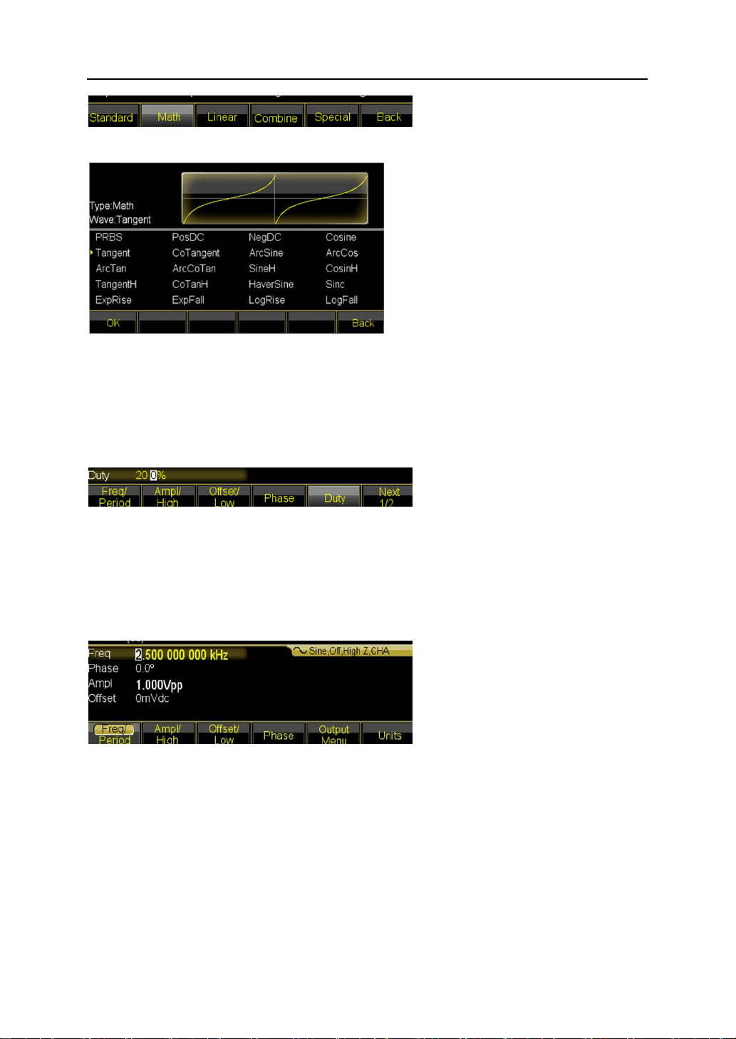
Press〖Waveform〗key again to back to current menu.
4.3.3 To set duty cycle
For example, specify a duty cycle of Square to 20%.
Press 〖Duty Cycle〗softkey and then set the duty cycle to 20% using the numeric keypad
or the knob and arrow keys 【<】【 >】. If you use the keypad, press 〖%〗softkey to finish
entering the value.
4.3.4 To set Frequency
For example, specify a frequency to 2.5kHz.
Press 〖Freq/period〗softkey and then set the frequency to 2.5kHz using the numeric
keypad or the knob and arrow keys 【<】【 >】. If you use the keypad, press 〖kHz〗 softkey
to finish entering the value.
4.3.5 To set Amplitude
For example, specify amplitude to 1.6Vrms.
Press 〖Ampl/High〗softkey and then set the amplitude to 1.6Vrms using the numeric
keypad or the knob and arrow keys 【<】【>】. If you use the keypad, press 〖Vrms〗
softkey to finish entering the value.
10
Page 11

4.3.6 To set offset
For example, specify an offset to -25mVdc.
Press 〖Offset〗softkey and then set the offset to -25mVdc using the numeric keypad or
the knob and arrow keys 【<】【>】. If you use the keypad, press 〖mVdc〗 softkey to
finish entering the value.
4.3.7 To output an AM waveform
A modulated waveform consists of a carrier and a modulation waveform. In AM, for
example, you want to output an AM waveform with 80% modulation depth, the carrier will
be 10kHz and the modulation waveform will be a 10Hz Ramp wave.
1. Select AM
Press 【Modulate】key and then select 〖AM〗softkey by pressing the〖Mod Type〗softkey.
2. To set Carrier frequency
Press〖Carrier〗to enter into the parameter setting. Then press〖Freq〗softkey, enter 10
kHz with the numeric keypad or the knob and arrow keys. Press 〖kHz〗softkey to finish
entering the number.
3. To set the modulation depth
11
Page 12
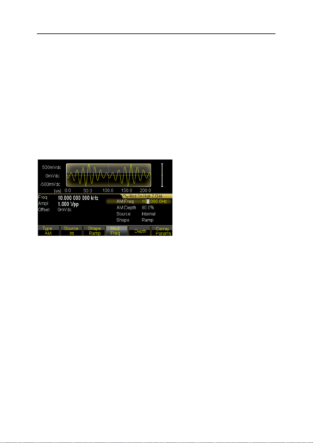
Press 〖Return〗key to back to parameter setting and press the 〖Depth〗softkey and then
set the value to 80% using the numeric keypad or the knob and arrow keys. Press 〖%〗
softkey finish entering the number if you are using the numeric keypad.
4. To set modulating waveform frequency
Press 〖AM Freq〗softkey and then set the value to 10 using the numeric keypad and
finally press〖Hz〗softkey.
5. To select the modulation waveform shape
Press the 〖Shape〗softkey then press 【Ramp】key to set the shape of modulating
waveform as Ramp.
6. To set AM parameters by knob or arrow keys
4.3.8 To output an Sum waveform
If you want to output a Sum waveform with amplitude 10% and modulation waveform is
Ramp.
1. Select Sum
Press 【Modulate】key and then select 〖Sum〗softkey by pressing the 〖Mod Type〗
softkey.
2. To set the Sum amplitude
Press the 〖Sum Ampl〗softkey and then set the value to 10 using the numeric keypad
and finally press〖%〗softkey, or set by the knob and arrow keys.
3. To select the modulation waveform shape
Press the 〖Shape〗 softkey then press 【Ramp】 key to set the shape of modulating
waveform as Ramp.
4. Generator output a sum waveform as preset modulating parameters and you also
can adjust amplitude of summed ramp by 【<】or 【>】keys.
12
Page 13
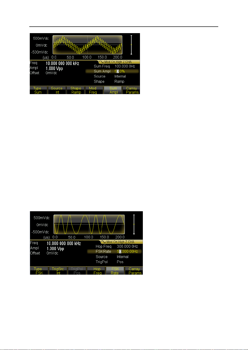
4.3.9 To output a FSK waveform
If you want to output a FSK waveform with hop frequency to 300Hz, with an FSK rate of
50Hz,
1. Select FSK
Press 【Modulate】key and then select 〖FSK〗softkey by pressing the 〖Mod Type〗
softkey.
2. Set the hop frequency
Press the 〖Hop Freq〗softkey then set the value to 300Hz using the numeric keypad or
the knob and arrow keys.
3. Set the FSK rate
Press the 〖Hop Rate〗softkey then set the value to 50Hz using the numeric keypad or
the knob and arrow keys.
4. Set the hop frequency and FSK rate by knob or arrow keys.
4.3.10 To output a Frequency Sweep
If you want to output an swept waveform with sweep time of 5 second, logarithmic
sweep,
1. Select Frequency sweep
13
Page 14
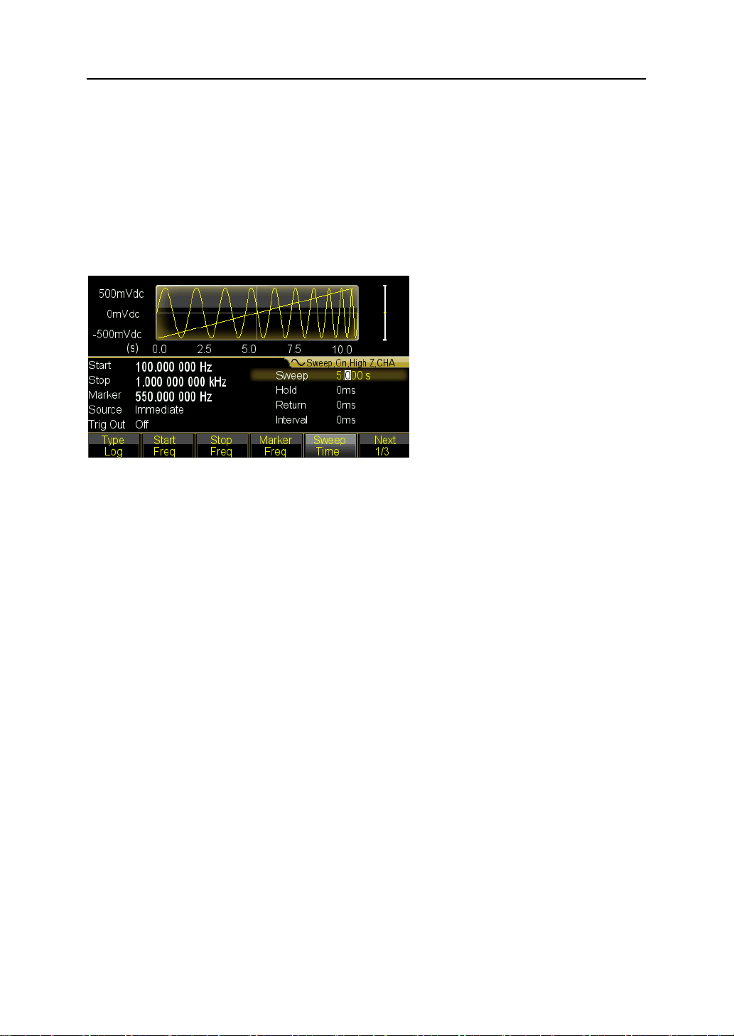
Press 【Sweep】key and then verify that the Sweep is selected in default.
2. Select sweep time
Press the 〖Sweep Time〗softkey then set the value to 5s using the numeric keypad or
the knob and arrow keys.
3. Select sweep mode
Press the 〖Mode Line/Log〗softkey and then verify that the logarithmic sweep mode is
currently selected on the first softkey.
4.3.11 To output a Burst waveform
If you want to output a five-cycle wave with a 10ms burst period, continuous or manual
signal trigger.
1. Press 【Burst】key then burst menu is shown in the screen of the current channel.
2. Press 【Burst Mode】and select the ‘Triggered’.
3. Press 〖Burst Period〗softkey then set the value to 10ms using the numeric keypad
or the knob and arrow keys.
4. Press 〖N Cycle〗 softkey then set the value to 5 using the numeric keypad or the
knob. Press the 〖Ok〗 softkey to finish data entry if you are using the numeric
keypad.
At this point, the waveform generator outputs a continuous five-cycle burst at 10 ms
intervals.
14
Page 15
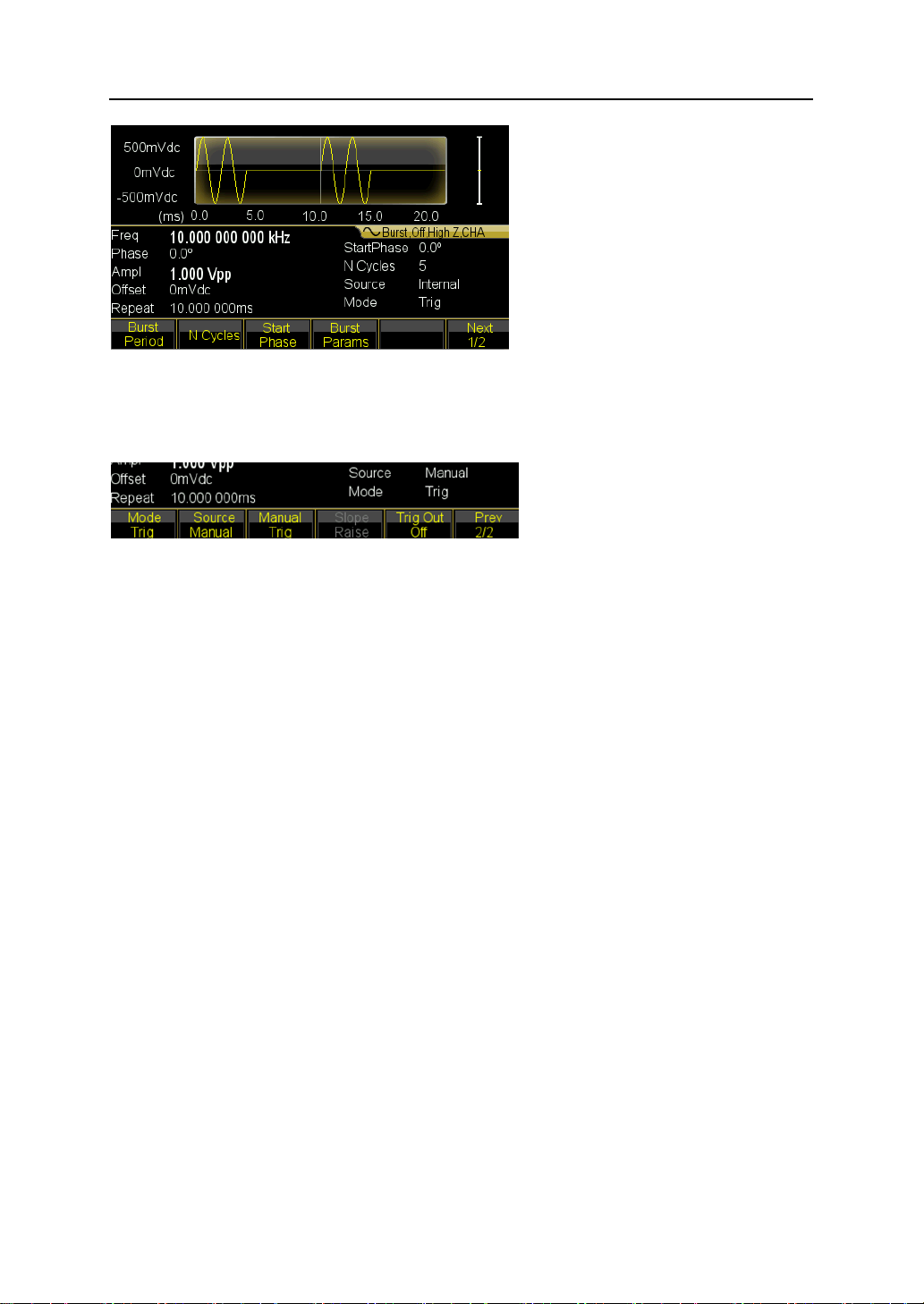
You also can generate signal burst (still with 5 cycles) by selecting Manual Trig under
pressing 〖Source Int/Ext〗softkey. Then each time you press 〖Manual Trig〗softkey, one
five-cycle burst will be output. Press number depends on the desired burst number.
4.3.12 Frequency Coupling
If you want to couple frequencies between the two channels,
1. Press 【Dual Channel】key. The dual channel menu is shown in the current screen.
2. Press the 〖Freq Cpl〗softkey to turn frequency coupling on. Then press 〖More〗
softkey to configure frequency coupling.
3. Press 【 Continuous】 key to configure CHA frequency, just because channel
frequencies can be linked with a constant ratio or difference between them, CHB
frequency will be changing as CHA changes.
4.3.13 Frequency Counter
If you want to measure a frequency of external signal,
1. Press 【Counter】key to enter into Counter mode and display the counter menu and
count results.
2. Input measured signal through ‘Counter’ connector at rear panel.
3. Press 〖Meas Type〗softkey, the generator begin to measure then display the
measured frequency value.
4. For Square input, press 〖Duty cyc〗softkey to enable the duty cycle measurement
and display the duty cycle.
15
Page 16

Key
Working Mode
【Continuous】
Continuous output
【Modulate】
Modulate output
【Sweep】
Sweep output
【Burst】
Burst output
【Dual Channel】
Dual channel operation
【Counter】
Frequency counter
No.
Waveform
No.
Waveform
Standard Waveforms 5
00
Sine
03
Pulse
01
Square
04
Noise
02
Ramp
Math Waveforms 36
05
PRBS
23
LogRise
06
PosDC
24
LogFall
07
NegDC
25
PosSquare
08
Cosin
26
NegSquare
5.Features and Functions
This chapter makes it easy to look up details about a particular feature of the waveform
generator. It also covers the front-panel operations. You should read Chpter2
‘Front-panel Menu Operation’ first and master the basic operation so as to get a better
understanding for this chapter.
5.1 Working Mode
There are six working modes for the waveform generator,
While,
CHA and CHB both cover four modes: continuous output, modulate output, sweep output
and burst output.
Notice that the modulate output covers thirteen types: AM, FM, PM, PWM, SUM, FSK,
QFSK, 4FSK, PSK, QPSK, 4PSK, ASK, OSK.
And sweep output covers three types: Frequency Linear Sweep, Frequency Logarithm
Sweep and Frequency List sweep.
5.2 Continuous Output
5.2.1 Waveform Selection
The waveform generator can output 150 waveforms, see below table,
16
Page 17

09
Tangent
27
PosCube
10
CoTangent
28
NegCube
11
ArgSine
29
SquareRoot
12
ArgCos
30
PosRecipro
13
ArgTan
31
NegRecipro
14
ArgCoTan
32
PNRecipro
15
SineH
33
BiRecipro
16
CosinH
34
PosSemicirc
17
TangentH
35
NegSemicirc
18
CoTangentH
36
Gaussian
19
HaverSine
37
Maxwell
20
Sinc
38
Lorentz
21
ExpRise
39
Laplace
22
ExpFall
40
Besell
Linear Waveforms
41
PosPulse
59
PNTriangl
42
NegPulse
60
HiLoTri
43
PN_Pulse
61
LoHiTri
44
PosBiPulse
62
PosRiseRamp
45
NegBiPulse
63
PosFallRamp
46
PNBiPulse
64
RiFaRamp
47
PMulPulse
65
NegRiseRamp
48
NMulPulse
66
NegFallRamp
49
PNMulPulse
67
FaRiRamp
50
WidePulse
68
Trapezia
51
NarrowPulse
69
RiseStair
52
WiNaPulse
70
FallStair
53
HiLoPulse
71
RiFaStair
54
RisePulse
72
RiStariRamp
55
FallPulse
73
FaStariRamp
56
RiFaPulse
74
Spiry
57
PosTriangl
75
Swallow
58
NegTriangl
76
Chair
Combine Waveforms 40
77
PAllSine
97
SineFSK
78
NAllSine
98
SinePSK
79
PHalfSine
99
SineSum
80
NHalfSine
100
SineSweep
81
SiAmplCut
101
AmplInc
82
BiAmplCut
102
AmplDec
83
SiPhaselCut
103
BurstNoise
84
BiPhaselCut
104
BurstSine
85
SinePulse
105
LowPass
17
Page 18

86
NoisePulse
106
HighPass
87
BiHarmo
107
BandPass
88
TriHarmo
108
BandPit
89
FourthHarmo
109
PulseOSC
90
FifthHarmo
110
PulseOver
91
SineFM
111
PNCircle
92
SineAM
112
Tripagoda
93
SquareAM
113
Candela
94
NoiseAM
114
ExpSquare
95
PulsePWM
115
ExpSine
96
SineFSK
116
TanSquRoot
Special Waveforms 32
117
TanArcTan
133
Cardiac2
118
ReciInvReci
134
NearQuake
119
HarmInvHarm
135
FarQuake
120
BiReciHarm
136
Blast
121
BiReciCircle
137
Shake
122
CubeGause
138
LandScape
123
TanHarm
139
Cloud
124
HalfBiReci
140
Camel
125
Charge
141
User_arb1
126
Stress
142
User_arb2
127
HeatTreat
143
User_arb3
128
MulHarm
144
User_arb4
129
Syntony
145
User_arb5
130
Stereo
146
User_arb6
131
RainFall
147
User_arb7
132
Cardiac1
148
User_harmo
Edit Waveform 1
149
Edit_wave
(1) 00~04 are standard common used waveforms.
05~140 are built-in waveforms which are used in special occasion.
141~147 are user-defined arbitrary waveforms, allows to be saved by users after
creating with software.
148 is used to save the user-defined harmonic wave.
149 is edit waveform, used to edit and modify arbitrary wave or harmonic wave. If
not save, the data will be lost once exit this function.
(2) Press 【Waveform】 key to see the waveform menu, select Sine, Square, Ramp,
Pulse or Noise from the options. Press〖Arb〗key and then〖Built-in〗option to select
built-in waveforms from 150 waveforms.
18
Page 19

Built-in waves have five types: Standard, Math, Linear, Combine and Special. Press
the option to enter into the waveform list and then select desired waveform by
left/right key or knob. Finally press〖Confirm〗to output selected waveform from the
output port, the sketch also be shown at the display.
Press 〖Back〗key to return to type menu and you can select other types of built-in
waveform again. Press〖Back〗key again to exit the built-in waveform menu. Or
press 【Waveform】key to return to current function window.
(3) The selected waveform diagram is shown but which is just a sample one with lower
resolution. Observe and test the output waveforms using oscilloscope.
5.2.2 Duty Cycle (Square or Pulse)
The duty cycle represents the fraction of time per cycle that the square wave is at a high
level. Press 【Waveform】key and choose Square or Pulse, press 〖Duty Cycle〗softkey
after selecting 【Continuous】key then set the desired value of duty cycle. Usually, the
duty cycle value remains unchanged if the Square frequency is changing, but duty cycle
is limited by the edge time if output frequency is too high, which should comply with the
below formula:
10ns ≤ ( Duty Cycle × Period ) ≤ ( Period-10ns )
5.2.3 Pulse Width and Edge Time
The pulse width represents the time from the 50% threshold of the rising edge of the
pulse to the 50% threshold of the next falling edge. After selecting the pulse function,
press the 〖Pulse Width〗 softkey. Then use the knob or numeric keypad to enter the
desired pulse width. The pulse width usually remains unchanged if the Square frequency
is changing, but will be limited by the edge time if output frequency is too high, which
should comply with the below formula:
10ns≤Pulse Width≤ Period-10ns
The edge time represents the time from the 10% threshold of rising/falling edge to 90%
of which. If select Pulse waveform in continuous menu, press 〖Edge Time〗 to select the
Edge parameter to set. The edge time setting will be also limited by pulse width, which
should comply with the below formula:
Edge Time≤0.625×Pulse Width
Edge Time≤0.625×Duty Cycle×Period
19
Page 20

5.2.4 Symmetry (Ramp)
Symmetry represents the fraction of time per cycle that the ramp wave is rising. After
selecting the ramp, press 〖Ramp Symmetry〗then set the desired value of symmetry.
The symmetry will remain unchanged if output frequency is changing. Rising Ramp will
be shown when symmetry is 100%, falling ramp will be shown when symmetry is 0%,
triangle wave display when symmetry is 50%.
5.2.5 Set Frequency
The output frequency range depends on the function currently selected and the upper
limit for sine depends on the model selected. The minimum frequency is 1μHz for all
functions. For detail specification, please see chapter 5. If you change to a function
whose maximum frequency is less than that of the current function, the frequency is
adjusted to the maximum value for the new function. The distortion will go increasing as
frequency rising.
To set the output frequency, press the 【Continuous】key, then the 〖Freq/Period〗
softkey for the selected function. Then use the knob or numeric keypad to enter the
desired frequency. Or press 〖Freq/Period〗 softkey again to set using Period. For
internally applying to frequency synthesis, the display period value is the conversed one
from enter value.
5.2.6 Set Amplitude
You can set amplitude by ‘amplitude’ or ‘level’. If amplitude set is selected, high level and
low level of signal will change at the same time when changing amplitude but DC offset
remain unchangeable. If level set is selected, no matter high level or low level changing,
low or high level remain unchangeable but DC offset will change. The relationships
between Vpp, High, Low and offset are shown below:
Vpp=High-Low High=Offset+Vpp/2 Low=Offset-Vpp/2
In continuous menu, press softkey 〖Ampl/High lev〗to set amplitude or high level. Press
softkey 〖Offset/Low lev〗 to set dc offset or low level.
5.2.7 Amplitude Limitation:
The output amplitude is limited by following factors. Once over the limitation, the
generator will modify the setting as its allowed maximum within the limitation.
(1) Limit Level: press 〖Ouput Menu〗softkey and then〖High Lev Limit〗softkey specify
the limit value of high level. Press〖Low Lev Limit〗softkey specify the limit value of
low level. Even if wrong operation that exceed the limit value, the generator won’t be
20
Page 21

Waveform
Vpp
Vrms
Sine
2.828Vpp
1Vrms
Square, Pulse
2Vpp
1Vrms
Ramp
3.464Vpp
1Vrms
Vpp
Vrms
dBm
10.0000 Vpp
3.5356 Vrms
23.979 dBm
6.3246 Vpp
2.2361 Vrms
20.000 dBm
2.8284 Vpp
1.0000 Vrms
13.010 dBm
2.0000 Vpp
707.1 mVrms
10.00 0dBm
1.4142 Vpp
500.0 mVrms
6.9897dBm
damage and perform within the limit value. But if specify the high level value to be
+10Vdc and low level to be -10Vdc, the limit function won’t work anymore.
(2) DC offset: except that set DC offset as 0, the amplitude is only limited by limit level,
otherwise, which is further limited by DC offset, as following regulation:
DC offset + Vpp/2≤High Limit
DC offset – Vpp/2≥Low Limit
(3) Frequency: if frequency high enough, allowed maximum amplitude will be limited
(refer to chapter 5, Specifications)
(4) Channel Bandwidth: the output amplitude will decrease if frequency is higher. So
flatness compensation will be needed to ensure the accurate amplitude in
continuous output. But for other functions, once the frequency over 10MHz, the
amplitude will decrease.
(5) For the arbitrary waveform generator, if Vpp don’t reach to full range, the display
value is not agreed with the output value.
5.2.8 Amplitude Units: You can set the output amplitude in Vpp, Vrms, or dBm. Vpp is
available for all functions. For sine, square, ramp and pulse, Vrms can also be used. The
output units for amplitude can also be set to dBm if the external load is currently set to
‘non High Z’.
(1) In continuous mode, press〖Ampl Unit〗select units if current waveforms and load
condition allows. Different unit key will enable the different format displaying.
(2) For different waveforms, the convert relationship between Vrms and Vpp is subject
to, see below table:
(3) The relationship among dBm and Vrms and Vpp is subject to waveform and load,
dBm=10×log10(P/0.001), while, P=(Vrms)2/Load
If waveform is sine, set 50Ω load, the convert among three output units is shown below,
21
Page 22

632.5 mVpp
223.6 mVrms
0.00 dBm
282.9 mVpp
100.0 mVrms
-6.9879dBm
200.0 mVpp
70.7 mVrms
-10.000 dBm
10.0 mVpp
3.5 mVrms
-36.020 dBm
5.2.9 Set DC offset
Press 〖Offset/Low lev〗softkey then set the desired offset value using the knob or
numeric keypad. Here, enter by knob is strongly recommend because of more
convenience feature. The DC offset setting will limit by amplitude and level, which should
be agreed with below formula:
Low Limit+Vpp/2≤Offset≤High Limit-Vpp/2
If the specified offset out of the range, the waveform generator will automatically adjust it
to the maximum DC voltage allowed with the amplitude specified.
If set amplitude to 0.2mVpp, high level limit to +10Vdc and low level limit to -10Vdc, then
the offset can be set within ±10V range. The waveform generator become the DC power
supply and can output DC voltage signal. But the thing to be noted is that the output
impedance is 50Ω.
5.2.10 Set Phase
Press 〖Phase〗softkey to select ‘Phase’ then set the desired phase using the numeric
keypad or knob.Output phase means the phase difference between output signal and
synchronous signal, and output signal advance to synchronous signal.
If frequency is same for CHA and CHB, press 〖Output Menu〗softkey to select 〖Phase
Sync〗to make the synchronous signal of CHA and CHB are with same phase. So it’s
easy to calculate the phase difference of two channels on basis of the phase setting for
CHA and CHB.
5.2.11 Set Polarity
In continuous mode, press 〖Output Menu〗and then〖Polarity〗softkey to set the polarity
of output signal.
(1) If select Normal, it means output waveform same as sketch. Take Sine for example,
normal polarity means output waveform start from zero phase and voltage goes
rising.
(2) If select Inverse, it means output waveform will be take voltage 0V as axes, and
generates the vertical image opposite to Normal polarity.
(3) Polarity setting has no influence to DC offset volts and Sync signal.
22
Page 23

5.2.12 External Load
In continuous mode, press 〖Output Menu〗and then〖Load〗softkey to set the external
load.
(1) The waveform generator has a fixed output impedance of 50Ω, the actual volts
value at the load is the standoff ration that load impedance to 50Ω. If change output
termination setting to higher, the standoff ratio will more approximate to 1, the error
between actual volts at the load and displayed amplitude or offset will become more
less. But if external load too lower, the actual volts will be not agreed with displayed
value.
(2) In order to make actual volts be agreed with display value, you should set suitable
external load.
Press 〖50Ω〗key to set external load as 50Ω.
Press 〖High Z〗key to set external load as High Z.
Press 〖Impedance〗key to set external load as desired value.
When setting of external load changes, the amplitude and offset display also
changes, but the actual output never change. Now you connect an external load to
output termination and make the actual value equals to setting, the actual voltage on
load will be same as the displayed value.
(3) When power on, the default external load is High Z.
(4) Note that most output termination are not totally resistive, because the inductive
impedance and capacitive impedance vary with frequency, especially when
frequency high, that the variation can’t be ignored. If actual impedance of output
termination are not confirmed, you can change the setting of ‘Load’ gradually and
make the actual volts are in line with displayed value, then final setting value for
‘Load’ is the actual impedance.
5.2.13 Output Control
The waveform generator has a output impedance of 50Ω, and it won’t be dam aged once
instantaneous short-circuit. If an excessive external voltage is applied to a front-panel
channel output connector by an external circuit, the instrument will disable the output and
generate an error message with sound alarm. To re-enable the output, remove the
overload from the connector and press 【Output】key to enable output. But this function
is not absolutely safe, and long-time short circuit or too excessive external voltage is
forbidden.
23
Page 24

5.2.14 Data Out of Range
As mentioned above, the parameters of frequency and amplitude have the specified
allowed range. Once out of range, the waveform generator will modify the setting
automatically, or modify the relative other parameters. Meantime, send an error message
with sound alarm. Data out of range won’t cause damage to instrument. But display
value maybe not the expected one, the generator will alarm again to remind you set it
again.
5.3 Frequency Modulation (FM)
In FM, carrier frequency varies with the instantaneous voltage of modulating waveform.
Press 【Modulate】key to enter into the Modulating output mode, the working mode
displays as Mod. Then press〖Type〗and select FM mode, displaying the FM sketch and
FM menu.
5.3.1 Set Carrier
Firstly, set the shape, frequency, amplitude and offset of Carrier Waveform. You can
select most waveforms from above table to be carrier, but some waveforms are not
available.
5.3.2 Frequency Deviation
Press 〖Freq Dev〗softkey to set value of Freq Dev. The frequency deviation setting
represents the peak variation in frequency of the modulated waveform from the carrier
frequency. When the amplitude of the modulated waveform is at positive peak value, the
output frequency is equal to the frequency of the carrier plus the frequency deviation,
and when it is at the negative peak value, the output frequency is equal to the carrier
frequency minus the frequency deviation. Therefore, the frequency deviation setting
must conform to the following two conditions:
Carrier frequency – Frequency deviation > 0
Carrier frequency + Frequency deviation < upper limit frequency of waveform
generator
5.3.3 Modulating Waveform Frequency
After selecting FM, press 〖FM Freq〗softkey then enter the desired value. Usually the
modulating waveform frequency should be set far less than the carrier frequency.
24
Page 25

5.3.4 Modulating Waveform Shape
Press 〖Shape〗softkey then select ‘Shape’ to set. Press 〖Waveform Menu〗to select
the desired waveforms in above table as modulating waveform. Finally, return to FM
menu.
5.3.5 Modulating Source
The waveform generator will accept an internal or external modulation source for FM.
Press 〖Source Int/Ext〗softkey. It’s available to set modulating frequency and modulating
waveform if ‘Internal’ source is selected. But if you select External source, the carrier
waveform is modulated with an external waveform. The frequency deviation is same as
actual value if amplitude 5Vpp, dc offset 0Vdc signal level present on the rear-panel
<Mod In> connector.
5.4 Amplitude Modulation (AM)
In AM, carrier amplitude varies with the instantaneous voltage of modulating waveform.
Press 【Modulate】key to enter into the Modulating output mode, the working mode
displays as Mod. Then press〖Type〗and select AM mode, displaying the AM sketch and
AM menu.
5.4.1 Set Carrier
Firstly, set the shape, frequency, amplitude and offset of Carrier Waveform. You can
select most waveforms from above table to be carrier, but some waveforms are not
available.
5.4.2 Modulation Depth
Press〖Depth〗softkey then set desired depth using knob or numeric keypad. The
modulation depth is expressed as a percentage and represents the extent of the
amplitude variation. If the maximum amplitude of modulating carrier is expressed as
Amax, the minimum amplitude Amin, setting value of amplitude as A and modulation
depth as M, the relationship among the four factors are expressed as following:
Amax=(1+M)×A/2.2 Amin=(1-M)×A/2.2
Therefore,
M=(Amax-Amin)×1.1/A
If modulation depth at 120%, then Amax=A and Amin= -0.09A. If modulation depth at
100%, then Amax=0.909A and Amin=0. If modulation depth at 50%, then Amax=0.682A
and Amin=0.227A. If modulation depth at 0%, then Amax=0.455A and Amin=0.455A.
25
Page 26

This is to say, when the modulation depth is at 0, carrier amplitude is a half of amplitude
setting.
5.4.3 Modulating Waveform Frequency
Press 〖AM Freq〗softkey to set the value of AM frequency. Usually the modulating
frequency should be far lower than carrier frequency.
5.4.4 Modulating Waveform Shape
Press 〖Shape〗softkey then select ‘Shape’ to enter the desired wave. Press Waveform
Menu key, then select one of most waveforms in above as modulating waveform. Finally,
return to modulating menu.
5.4.5 Modulating Source
The waveform generator will accept an internal or external modulation source for AM.
Press 〖Source Int/Ext〗softkey. It’s available to set modulating frequency and modulating
waveform if ‘Internal’ source is selected. But if you select External source, the carrier
waveform is modulated with an external waveform. The Modulating Depth is same as
actual value if amplitude 5Vpp, dc offset 0Vdc signal level present on the rear-panel
<Mod In> connector.
5.5 Phase Modulation (PM)
In PM, carrier phase varies with the instantaneous voltage of modulating waveform.
Press 【Modulate】key to enter into the Modulating output mode, the working mode
displays as Mod. Then press〖Type〗and select PM mode, displaying the PM sketch and
PM menu.
5.5.1 Set Carrier
Firstly, set the shape, frequency, amplitude and offset of Carrier Waveform. You can
select most waveforms from above to be carrier, but some waveforms are not available.
5.5.2 Phase Deviation
Press〖Phase Dev〗softkey then enter the desired value using knob or keypad. The phase
deviation setting represents the peak variation in phase of the modulated waveform from
the carrier waveform. If at positive peak value, the phase of output signal increases one
phase deviation. If at negative peak value, the phase of the output signal will decrease
one phase deviation.
26
Page 27

5.5.3 Modulating Waveform Frequency
Press 〖PM Freq〗softkey then set the desired value using knob or keypad. Usually the
modulating frequency should be far lower than carrier frequency.
5.5.4 Modulating Waveform Shape
Press 〖Shape〗softkey then select ‘Shape’ to enter the desired wave. Press Waveform
Menu key, then select most waveforms from above table as modulating waveform, but
some waveforms are not available. Finally, return to modulating menu.
5.5.5 Modulating Source
The waveform generator will accept an internal or external modulation source for PM.
Press 〖Source Int/Ext〗softkey. It’s available to set modulating frequency and modulating
waveform if ‘Internal’ source is selected. But if you select External source, the carrier
waveform is modulated with an external waveform. The phase deviation is same as
actual value if amplitude 5Vpp, dc offset 0Vdc signal level present on the rear-panel
<Mod In> connector.
5.6 Pulse Width Modulation (PWM)
In PWM, carrier phase varies with the instantaneous voltage of modulating waveform.
Press 【Modulate】key to enter into the Modulating output mode, the working mode
displays as Mod. Then press〖Type〗and select PM mode, displaying the PWM sketch
and PWM menu.
5.6.1 Set Carrier
Firstly, set the frequency, amplitude and offset of Carrier Waveform. In PMW mode, the
generator will set carrier as pulse automatically and the pulse width of carrier changes
along with transient voltage and only allows the pulse for carrier.
5.6.2 Pulse Width Deviation
The PWM deviation setting represents the peak variation in width of the modulated pulse
waveform. Press 〖Width Dev〗softkey then enter the desired value using the knob or
keypad. If at positive peak value, the pulse width of output signal equals to setting value
of pulse width plus deviation. If at negative peak value, the pulse width of output signal
equals to setting value of pulse width decrease a deviation.
27
Page 28

5.6.3 Modulating Waveform Frequency
Press 〖PWM Freq〗softkey then set the desired value using knob or keypad. Usually the
modulating frequency should be far less than carrier frequency.
5.6.4 Modulating Waveform Shape
Press 〖Shape〗softkey then select ‘Shape’ to enter the desired wave. Press Waveform
Menu key, then select one of most waveforms from above table as modulating waveform,
but some waveforms are not available. Finally, return to modulating menu.
5.6.5 Modulating Source
The waveform generator will accept an internal or external modulation source for PWM.
Press 〖Source Int/Ext〗softkey. It’s available to set modulating frequency and modulating
waveform if ‘Internal’ source is selected. But if you select External source, the carrier
waveform is modulated with an external waveform. The pulse width deviation is same as
actual value if amplitude 5Vpp, dc offset 0Vdc signal level present on the rear-panel
<Mod In> connector.
5.7 Sum Modulation
In Sum Modulation, the instantaneous voltage of output waveform is the sum voltage of
carrier and modulating waveform.
Press 【Modulate】key to enter into the Modulating output mode, the working mode
displays as Mod. Then press〖Type〗 and select SUM mode, displaying the sum
modulating sketch and SUM menu.
5.7.1 Set Carrier
Firstly, set the shape, frequency, amplitude and offset of Carrier Waveform. In Sum, the
instantaneous voltage of output waveforms equals to sum voltage of carrier waveform
and modulating waveform. You can select one of most waveforms from above table to be
carrier, but some waveforms are not available.
5.7.2 Sum Amplitude
Press 〖Sum Ampl〗 and select Sum Ampl parameter to set the sum amplitude value.
The sum amplitude represents the amplitude of the signal added to the carrier (in percent
of carrier amplitude). When sum amplitude at 100%, amplitude of modulating waveform
is a half of amplitude of carrier waveform. When sum amplitude at 0%, amplitude of
modulating waveform is 0, then amplitude if carrier waveform will be half of setting value
for carrier waveform.
28
Page 29

5.7.3 Modulating Waveform Frequency
Press 〖Sum Freq〗softkey then set the desired value using knob or keypad. Different
from other modulating mode, the modulating frequency can be highly greater than carrier
frequency.
5.7.4 Modulating Waveform Shape
Press 〖Shape〗softkey then select ‘Shape’ to enter the desired wave. Press Waveform
Menu key, then select one of most waveforms from above table as modulating waveform,
but some waveforms is not available. Finally, return to modulating menu.
5.7.5 Modulating Source
The waveform generator will accept an internal or external modulation source for Sum.
Press 〖Source Int/Ext〗softkey. It’s available to set modulating frequency and modulating
waveform if ‘Internal’ source is selected. But if you select External source, the carrier
waveform is modulated with an external waveform. The sum amplitude is same as actual
value if amplitude 5Vpp, dc offset 0Vdc signal level present on the rear-panel <Mod In>
connector.
5.8 Frequency -Shift Keying Modulation (FSK)
In FSK mode, output signal hop between Carrier Frequency and Hop Frequency, the
hopping rate decided by FSK rate.
Press 【Modulate】 key then select the FSK mode. The FSK modulating waveform
sketch and FSK menu will be both displayed. The selection of FSK mode includes FSK,
QFSK, and 4FSK.
5.8.1 Set Carrier
Firstly, set the shape, frequency, amplitude and offset of Carrier Waveform. You can
select most waveforms from above table to be carrier, but some waveforms are not
available.
5.8.2 Hop Frequency
FSK modulation is similar to FM that modulating waveform is Square. And hop frequency
is similar to frequency deviation. But the difference is that, frequency deviation is the
frequency of carrier wave plus or minus deviation value, whose setting range is relational
with the frequency of carrier wave, while hop frequency has no relationship with it. Press
〖Hop Freq〗softkey to set the desired value of hop frequency.
29
Page 30

(1) FSK allows to be set hop frequency, which the carrier frequency and hop frequency
output by turns.
(2) 4FSK allows to be set for three hop frequencies, carrier frequency and three hop
frequencies output in sequence 1, 2, 3.
(3) QFSK also allows to be set for three hop frequencies, carrier frequency and three
hop frequencies output randomly.
5.8.3 FSK rate
To set the FSK rate, press 〖FSK Rate〗or 〖4FSK Rate〗or 〖QFSK Rate〗softkey. Then
use the knob or numeric keypad to enter the desired rate. FSK rate is generally lower
than carrier frequency.
5.8.4 Trigger Source
Press〖Trigger〗softkey. When Internal source selected, generator takes internal source
and shift rate setting is available. When External source selected, generator takes
external source and shift rate setting is disabled. Details refer to Chapter 3.14.
5.9 Phase Shift Keying Modulation (PSK)
In PSK, the phase of output signal alternately hop between carrier phase and hop phase,
and hop rate depends on shift keying rate.
Press 【Modulate】 key then select the PSK mode. The PSK modulating waveform
sketch and PSK menu will be both displayed. The selection of PSK mode includes PSK,
QPSK, and 4PSK.
5.9.1 Set Carrier
Firstly, set the shape, frequency, amplitude and offset of Carrier Waveform. You can
select one of most waveforms from above table to be carrier, but some waveforms are
not available.
5.9.2 Hop Phase
PSK modulation is similar to PM that modulating waveform is Square. And hop phase is
similar to phase deviation. Press 〖Hop Phase〗softkey to set the desired value of hop
phase.
(1) PSK allows being set hop phase, which the carrier phase and hop phase output by
turns.
(2) 4PSK allows to be set for three hop phases, carrier phase and three hop phases
output in sequence 1, 2, 3.
30
Page 31

(3) QPSK also allows to be set for three hop phase s, carrier phase and three hop
phase s output randomly.
5.9.3 PSK Rate
To set the PSK rate, press 〖PSK Rate〗or 〖PFSK Rate〗or 〖QPSK Rate〗softkey. Then
use the knob or numeric keypad to enter the desired rate. FSK rate is generally lower
than carrier frequency.
5.9.4 Trigger Source
Press〖Trigger〗softkey. When Internal source selected, generator takes internal source
and shift rate setting is available. When External source selected, generator takes
external source and shift rate setting is disabled. Details refer to Chapter 3.14.
5.10 Amplitude Shift Keying Modulation (ASK)
In ASK, the amplitude of output signal alternately hop between carrier amplitude and hop
amplitude, and hop rate depends on shift keying rate.
Press 【Modulate】 key then select the ASK mode. The ASK modulating waveform
sketch and ASK menu will be both displayed. The selection of ASK mode includes ASK
and OSK.
5.10.1 Set Carrier
Firstly, set the shape, frequency, amplitude and offset of Carrier Waveform. You can
select one of most waveforms from above table to be carrier, but some waveforms are
not available.
5.10.2 Hop Amplitude
In ASK, press〖Hop Ampl〗softkey and select Hop Ampl parameter to set the value. The
default setting for OSK hop amplitude is 0, so there is no Hop Ampl menu for OSK.
5.10.3 Hop Time
In OSK, press〖Hop Time〗softkey and select Hop Time parameter to set the value. Hop
Time represents the period of amplitude increases from 0 to maximum or decreases from
maximum to 0. In ASK, default hop time is 0 without menu option.
5.10.4 ASK Rate
Press 〖ASK Rate〗or〖ASK Rate〗softkey to set the value, that is modulating frequency,
which is far lower than carrier frequency.
31
Page 32

5.10.5 Trigger Source
Press〖Trigger〗softkey. When Internal source selected, generator takes internal source
and shift rate setting is available. When External source selected, generator takes
external source and shift rate setting is disabled. Details refer to Chapter 3.14.
5.11 Frequency Sweep
Press 【Sweep】 key to enter the sweep mode. The frequency sweep sketch and menu
will be both displayed.
5.11.1 Set Sweep Signal
Firstly, set up the waveform shape, amplitude and offset of sweep signal. In the
frequency sweep mode, the waveform generator moves from the start frequency to the
stop frequency at a sweep rate which you specify. It can span within the whole frequency
range and the phase of output signal is continuous. The waveform generator can
produce a frequency sweep for most waveforms mentioned above, but some waveforms
are not available.
5.11.2 Sweep Mode
Press〖Sweep Mode〗to select Linear or Log for sweeping.
(1) In Linear mode, frequency step is fixed. For wide sweep range, fixed step has
negative influence, which leads to high sweep resolution, slow sweep speed and
precise sweeping at high frequency, but low sweep resolution, fast sweep speed
and coarse sweeping at low frequency. Therefore, linear is much applicable for
narrow sweep range.
Linear sweep is similar as FM with modulating waveform ramp, the difference
between which is that no modulating wave needed for sweep, just output discrete
points in interval continuously.
(2) In Log mode, frequency step is not fixed but changes with log relationship. At high
frequency, the step is large and at low frequency step is less. For wide sweep range,
the variation is relative well-proportioned, so log sweep is applicable for wide sweep
range.
5.11.3 Start Frequency and Stop Frequency
Press the 〖Start Freq 〗or 〖Stop Freq〗 softkey. Then use the knob or numeric keypad
to enter the desired frequency.
32
Page 33

(1) To sweep up in frequency, set the start frequency less than the stop frequency.
(2) To sweep down in frequency, set the start frequency be greater than the stop
frequency.
5.11.4 Marker Frequency
Press〖Marker Freq〗softkey, then use the knob or numeric keypad to enter the desired
marker frequency. When sweeping cross the marker frequency point, the sync output
hop at the same time. The marker frequency must be set between the specified start
frequency and stop frequency. If out of the range, the waveform generator will
automatically set the marker frequency as the maximum or minimum allowed in the
sweep range.
3.11.5 Sweep Time
Press 〖Sweep Time〗softkey and use the knob or numeric keypad to enter the desired
sweep time. Sweep time represents the time required to sweep from the start frequency
to the stop frequency. The time interval to sweep from one frequency to next one is
constant, so more sweep time results in more sweep frequency points and finer sweep
step, vice visa.
5.11.6 Hold Time
Press 〖Hold Time〗 softkey and use the knob or numeric keypad to enter the desired
hold time. The hold time specifies the number of seconds to remain at the stop
frequency.
5.11.7 Return Time
Press 〖Return Time〗 softkey and use the knob or numeric keypad to enter the desired
return time. The return time specifies the number of seconds to return from the stop
frequency to the start frequency. No matter sweep mode is Linear or log,
5.11.8 Interval Time
Press 〖Interval Time〗softkey and select Interval parameter. Then use the knob or
numeric keypad to enter the desired interval time. The interval time specifies the time
from one sweep to next sweep. No matter sweep mode is Linear or log,
5.11.9 Trigger Source
Press〖Trig Imm/Ext〗softkey. When Immediate selected, the waveform generator takes
internal source and trigger sweep repeat running. When manual mode selected, the
waveform generator outputs one sweep each time you press 〖Manual Trig〗 softkey.
33
Page 34

When External selected, generator takes external source, the detail description refer to
chapter 3.14.
5.12 Frequency List Sweep
Press 【Sweep】 key to enter into sweep mode. the working mode displays as sweep,
the sweep sketch and menu will be both displayed.
5.12.1 Set Sweep Signal
First set the shape, amplitude and offset for sweep signal. The waveform generator can
produce a frequency list sweep for most waveforms mentioned above, but some
waveforms are not available.
In frequency sweep mode, the change of frequency only by linearly and logarithm, and
each point stand period during sweeping never change. So in some occasion, a
frequency list with arbitrary regularity or without any regularity need to be output, and
dwell time on each frequency point can be set, then list sweep will be used. In the
frequency list mode, the function generator “steps” through the frequencies contained in
a list, dwelling on each frequency for a specified period.
5.12.2 Sweep Mode
Press〖Sweep Mode〗and select List to display the list sweep menu.
5.12.3 Frequency List
Generator has default frequency list, which ranges from 1kHz to 128kHz. User can
create its own frequency list, the maximum length of which is 128 frequency value.
(1) Press 〖List Number〗softkey and set the desired list number.
(2) Press 〖List Freq〗will be automatically selected and set the frequency value
according to selected list number.
(3) Press 〖Next〗softkey can add 1 on list number and set the following frequency value.
Using this method to create or modify a frequency list.
(4) When complete the new list, you can save the current list by state storage method,
the the data of which won’t be lost even power-off and also could be recalled in
need. The detail method is referred to chapter 5.20.
5.12.4 Start Number and Stop Number
In the frequency list sweep mode, the waveform generator moves from the start number,
output each frequency value contained in a list one by one, until to the stop number.
34
Page 35

Press〖Start Number〗softkey to set start number. The start number should be less than
stop number, if not, the generator will set start number less 1 than stop number.
Press〖Stop Number〗softkey to set stop number. The stop number should be larger than
start number, if not, the generator will set stop number more 1 than start number.
5.12.5 Dwell Time
Press〖Dwell Time〗 softkey. Then use the knob or numeric keypad to enter the desired
dwell time. The dwell time specifies the number of seconds to remain at each frequency
point.
5.12.6 Hold Time
After enabling sweeps, press 〖Hold Time〗 softkey. Then use the knob or numeric
keypad to enter the desired hold time. The hold time specifies the number of seconds to
remain at the stop number.
5.12.7 Trigger Source
Press〖Trig Imm/Ext〗softkey. When Immediate selected, the waveform generator takes
internal source and trigger sweep repeat running. When manual mode selected, the
waveform generator outputs one sweep each time you press 〖Manual Trig〗 softkey.
When External selected, generator takes external source, the detail description refer to
chapter 5.14.
5.13 Burst Output
Press 【Burst】 key to enter into the sweep mode. The burst waveform sketch and burst
menu will be both displayed.
5.13.1 Set Burst Signal
First set the shape of burst signal. Normally sine is selected for burst signal, the other
buit-in waveform are also could be selected except of some waveforms. Press 〖Burst
Signal〗softkey to set frequency, amplitude and offset of burst signal.
5.13.2 Burst Mode
You can use burst in two modes by pressing 〖Mode Trig/Gat〗softkey to select.
(1) If ‘Triggered’ is selected, the waveform generator outputs a waveform with a
specified number of cycles (burst count) each time a trigger is received. After the
specified number of cycles have been output, the waveform generator stops and
waits for the next trigger.
35
Page 36

(2) If Gated is selected, only external source was available for trigger, the detail
description refer to chapter 5.14.
5.13.3 Burst Period
Press 〖Burst Period〗softkey to set the burst period. The burst period defines time from
the start of one burst to the start of the next burst. The burst period must be long enough
to accommodate the setting counts, see below formula,
Burst Period > Burst Count/Frequency of Burst Signal
If the burst period is too short, the waveform generator will automatically adjust it to be
allowed minimum value. Once the frequency of burst signal changes and leads to the
burst period can’t hold the burst count, the generator will automatically adjust it to be
allowed minimum value.
5.13.4 Burst Count
To set the burst count, press〖N Cycles〗 softkey The burst count defines the number of
cycles to be output per burst. The burst count must be short enough to be held in burst
period. See below formula to clarify the relationship between burst count and burst
period.
Burst Count < Burst Period×frequency of burst signal
If the burst count is too long, the waveform generator will automatically increase the burst
period up to its maximum value to accommodate the specified burst count
5.13.5 Burst Phase
The start phase defines the start time and stop time always at the same phase of
waveform for burst signal. To set the burst phase, press the 〖Burst Phase〗softkey.
5.13.6 Trigger Source
Press〖Trig Imm/Ext〗softkey. When Immediate selected, the waveform generator takes
internal source and output burst signal continuously. The setting of burst period is valid.
When manual mode selected, the waveform generator outputs one burst signal each
time you press 〖Manual Trig〗 softkey. When External selected, generator takes
external source and the setting of burst period is invalid, the detail description refers to
chapter 5.14.
36
Page 37

5.14 External Trigger Source
Generator has two bidirectional trigger ports on the rear panel <Trig In/Out>. When you
select external source, the trigger port is set as input from external trigger signal. When
you select internal source, the trigger port is set as output from internal trigger signal.
CHA is only for channel A and CHB is for channel B.
5.14.1 Trigger Level Input
When generator is under the function of FSK, 4FSK, QFSK, PSK,4PSK, QPSK, ASK,
OSK, user can input external trigger signal, which is digital logic level.
1. Press 〖Polarity〗softkey. If select “Positive”, the logic high level of trigger signal will
be set as “1”, the logic low level as “0”. If select “Negative”, the logic high level of
trigger signal will be set as “0” and logic low level as “1”.
2. If generator is under burst output function and burst mode selected as “ Gated”,
when trigger signal is “1”, the burst signal starts output. When trigger signal is “0”, it
will wait for the last periodic waveform and stops output. There will be at least two
cycles for gated output, the cycle of which should meet with the following
relationship:
Trigger Cycle> 2/Frequency of burst signal
3. If generator under FSK, PSK, ASK, OSK function, external signal will be input from
the trigger port. W hen trigger signal is “0”, it will output carrier frequency, carrier
phase and carrier amplitude, when trigger signal is “1”, it will output hop frequency,
hop phase and hop amplitude.
4. If generator under 4FSK, QFSK, 4PSK, QPSK, user need to input two digits of
trigger signal. The trigger port of original channel is inputted by low digit and the
other channel port by high digit.
When trigger signal is “00”, it outputs carrier frequency and carrier phase.
When trigger signal is “01”, it outputs hop frequency 1 and hop phase 1.
When trigger signal is “10”, it outputs hop frequency 2 and hop phase 2.
When trigger signal is “11”, it outputs hop frequency 3 and hop phase 3.
5.14.2 Trigger Edge Input
When generator under function of burst output or frequency sweep, user can input
external trigger signal, which is edge hoping.
37
Page 38

Press 〖Trig Edge〗softkey. If select “Rise”, the valid trigger edge is the hoping of trigger
signal from low to high. If select “Fall”, the valid trigger edge is the hoping of trigger signal
from high to low.
1. For burst output mode, when “Trigger” selected, each valid trigger edge burst output
the signal once, the cycle of trigger signal should meet with the following
relationship:
Trigger Cycle > Cycle number / Frequency of burst signal
2. For frequency sweep mode, each valid trigger edge finish triggering one sweep, the
cycle of trigger signal should be longer than the total sweep time, as below
relationship:
Trigger Cycle > Sweep Time + Hold Time + Return Time + Interval Time
3. For list sweep mode, each valid trigger edge finish triggering one sweep, the cycle
of trigger signal should be longer than the total sweep time, as below relationship:
Trigger Cycle > (Stop Number- Start Number) × Dwell Time + Hold Time
5.14.3 Trigger Output
For burst output, frequency sweep and list sweep mode, when internal or manual
selected as trigger source, the trigger port will be set as output port to output internal
trigger signal that is digital logic level, for triggering other device.
1. Press 〖Trig Out〗softkey. If select “Rise”, the trigger signal is logic high level when
selecting “1” for trigger output. If select “Fall”, the trigger signal is logic low level
when selecting “1” for trigger output. If select “Off”, there will be no output.
2. For burst output mode, the trigger port outputs “1” during the burst outputting and
outputs “0” for disabling the burst output.
3. For frequency sweep mode, when internal source selected, the trigger port outputs
“1” at start of sweeping, the pulse width of which should be half of total sweep time.
4. For list sweep mode, when internal source selected, the trigger port outputs “1” at
start of sweeping, the pulse width of which should be equal to dwell time.
5. For frequency sweep or list sweep mode, when manual selected, trigger port
outputs “1” at start of sweeping, the pulse width should be more than 100us.
5.15 Dual Channel Operations
You enter the dual channel configuration menu by pressing 【Dual Channel】key. The
working mode will display as Dual Setting, the instruction and menu of which will be both
38
Page 39

shown. It has two working modes, parameter coupling and waveform combine.
Parameter coupling contains Frequency Coupling and Amplitude Coupling.
5.15.1 Coupling Direction
The dual channels are identical and allowed to be coupled by both of each other. Press
〖Couple Direction〗softkey to set the coupling direction between channels.
If set A to B, A is source channel and B is object channel, vice versa. The direction is one
way to allow the source channel to be coupled to object channel.
Any mode of dual channel once enabled, the indicator of which will be lighted on and tells
user entering into the coupling state. And user only can operate source channel but not
the object channel.
5.15.2 Frequency Coupling
With frequency coupling function, generator can make the dual channel frequency output
relates and generates two multiplied frequency or differenced frequency signal.
(1) Press the 〖Freq Cpl On/Off〗 softkey to turn frequency coupling on, the dual
channels coupled function is enabled. When you change the frequency of source
channel, the frequency of object channel will change along with the source channel
automatically and not allowed to be independently set again. The frequency
relationship between two channels accords with the formula:
Frequency of object channel = frequency of source channel×frequency ratio +
frequency difference
(2) Press 〖Cpl Para〗softkey and enter into the parameter coupling menu. Press 〖Freq
Ratio〗and 〖Freq Diff〗softkey to specify the desired frequency ration and frequency
difference.
(3) Press the 〖Freq Cpl On/Off〗 softkey to turn frequency coupling off, the dual
channels coupled function is disabled and frequency can be set independently for
both of channels.
5.15.3 Amplitude Coupling
Amplitude coupling, which is enabled by the 〖Ampl Cpl On/Off〗 softkey, couples the
amplitude and offset voltage between the channels. When you change the amplitude or
offset of source channel, the amplitude or offset of object channel will change along with
the source channel automatically. Once select Off, the dual channels coupled function is
disabled and amplitude and offset can be set independently for both of channels.
39
Page 40

Press 〖Ampl Diff〗and 〖Offs Diff〗softkey to configure the desired amplitude difference
and offset difference. The amplitude coupling relationships of two channels are as below,
Amplitude of object channel = amplitude of source channel + amplitude difference
Offset of object channel = offset of source channel + offset difference
5.14.4 Waveform Combine
In waveform combine, select most waveforms mentioned above table except of some.
Waveform combine is similar to Sum modulation. The difference is that Sum modulation
use modulating waveform but waveform combine allows using continuous wave,
modulating wave, sweeping wave and bursting wave. Therefore, more complicated wave
can be generated for waveform combine.
Press 〖Combine On/Off〗softkey then select On to enable waveform combine feature.
The waveform of source channel can be combined with the one of object channel, then
output from the connector of object channel.
Enter into the parameter coupling menu and press 〖Combine Ampl〗softkey to set the
parameter of combine amplitude. Combine amplitude represents the source channel
amplitude superposed to object channel waveform, expressed by percentage of object
channel amplitude setting. For 100% combine amplitude, source channel amplitude
equals to the half of object channel amplitude. For 0% combine amplitude, source
channel amplitude is 0, now object channel amplitude is half of setting, the relationship
between dual channels are:
Combined waveform = source channel wave × combine amplitude + object channel
wave
5.15.5 Waveform Combine Example
Make use of waveform combine feature, the waveform generator can output some
special waveforms. For example, couple two narrow pulse on CHB. You can operate as
following steps:
(1) Enable CHA to be continuous, 10kHz Square with duty cycle 10%.
(2) Enable CHA to be burst again, burst period 1ms and burst count 2.
(3) Press 〖Dual Channel〗key and set the amplitude combine to be 50%.
(4) Press 〖Combine On/Off〗softkey then select On.
(5) Enable CHB to be continuous, 1kHz Sine.
(6) Then a Sine superposed by two narrow pulse at each period output from CHB
connector.
40
Page 41

5.15 Arbitrary Waveform
There are two types for arbitrary waveform setting, short and long arbitrary waveform,
the methods of which are same. Waveform length for short is 16384 (16k) points and
allows being set independently for dual channels. Waveform length for long is 1048576
(1M) points and only applicable for channel A.
5.15.1 Enter into the Waveform Edit
Press 【Waveform】key to display all the waveform option and select 〖Arbitrary〗key to
enter into the arbitrary waveform menu. If you want to create the waveform with length
less 16K points, you can press〖Create Normal〗key. If you want to create the waveform
with length more than 16K points, you can press〖Create Ultra Long 〗key. Once enter
into the window of waveform edit, generator pre-create one straight line with length of 20
points, voltage of each points is 0Vdc and sampling rate is 1MSa/s. The interface is as
below:
1.Votage Scale 2.X Cursor 3.Y Cursor(green) 4. Points
5. Editing Parameters 6. Current Cursor 7.Current Waveform (yellow)
5.15.2 Insert Built-in Waveform
To create a simple waveform, like a Pulse or Ramp, you can edit by “Point Edit” and
“Line Edit” methods manually. But for Sine, it is not so easy to edit manually because the
each point requires extremely accurate value. So the generator prepares 150 built-in
arbitrary waveform for users, the part of each waveform can be selected and inserted to
current edited waveform. Then user can correct, cut and copy it to complete the desired
complicated waveform, no need to edit point by point.
During the editing, user can change the parameters such as sampling rate, amplitude
and waveform length to alter the characteristic of editing waveform timely.
41
Page 42

Refer to next page and press 〖Insert Wave〗key to enter into the waveform selection
window. Select desired waveform and press〖Eneter〗key.
For your selected waveform, press 〖Waveform〗key to show a setting frame, which
allows the user to make parameter setting for the inserted waveform. Up/Down key for
select and knob for value setting, no option setting means default value.
(1) Amplitude: set the Vpp for inserted waveform
(2) Offset: set the DC offset voltage for inserted waveform
(3) Phase: set the start phase for inserted waveform, refer to the phase of which.
(4) Insert position: set the position (X -axis value) where the editing waveform you
want to be inserted.
(5) Total points: set the total points for inserted waveform. Generator abstract
points from inserted waveform at interval, which is also the waveform length of
inserted waveform.
When parameter setting finished, press 〖Return〗key to back editing window and you will
see the selected waveform locate at your desired position.
The example shows how to insert a sine wave with 200 points.
(1) press 〖Insert Wave〗key to enter into the waveform select interface. Then press
〖Normal Wave〗key and select Sine.
(2) Press 〖Enter〗to confirm the operation and then 〖Waveform〗key to display
parameter setting frame. Set amplitude to be 1.0Vpp, offset 0Vdc, phase 0°, insert
position 0, total points 200, as below picture:
(3) Keep press〖Return〗until back to edit waveform window and you will see the
inserted Sine as you set.
42
Page 43

5.15.3 Select Cursor
User can make more fast and accurate position for one point by using of Cursor.
Cursor setting has four types. Press 〖Cursor All〗and select “Cursor Off” to disable the
cursor. Select “Cursor X” to display one vertical cursor. Select “Cursor Y” to display one
horizontal cursor. Select “Cursor All” to display both of vertical and horizontal lines.
Only selecting X or Y axis, the cursor is valid. User will found cursor will be mainly
operated in following editing work.
5.15.4 Point Edit
Point edit can set voltage to one point on waveform, also can insert or delete one point at
specified location on waveform, which is applicable for locally modification to existing
waveform or create a simple waveform with less points.
The example shows how to locally modify, insert and delete the points to one sine with
100 points:
(1) Insert a sine with 100 points wave as the method introduced in chapter 5.15.2.
(2) Press 〖Point Edit〗key to enter into the editing window.
(3) Press 〖Select Point〗key and set the X-axis to be 10.
(4) Press 〖Point Voltage〗key and set the Y-axis to be 1.0V.
43
Page 44

Once X and Y cursor are both on, user can press 〖Select Point〗and turn the knob
to see the two cursor crossing moving along with the trace of sine, also the X and Y
axis value of each point. When cursor move to where X-axis is 0, Y-axis is 1.000V,
that is also the setting of step 4 and 5 above.
In picture, the value of X and Y axis are auto adjusted by varying of setting range.
The feature is applicable for other editing modes.
(5) Move the X-axis to 50 and repeat pressing〖Point Edit〗5 times, you will observe that
5 points with same voltage are added to where 50 points locates and total points are
plus 5:
(6) Move the Y-axis to 26 and repeat pressing 〖Point Delete〗10 times, you will observe
that 10 points are deleted at where 26 points locate and total point decreased 10.
5.15.4 Line Edit
For Line Edit, user only need to set two points and generator will follow the linear
regulation and auto set all the points between the two points, then connect which by a
line. So compared to Point Edit, Line Edit could be quicker at creating the waveform by
setting lots of points one time, applicable for linear modification to existing waveform or
create a line waveform.
44
Page 45

The example shows how to do linear modification to a sine wave with 100 points.
(1) Insert a sine wave with 100 points as the method introduced in chapter 5.15.2.
(2) Press 〖Line Edit〗key to enter into the editing window. X1 and Y1 indicate the start
coordinate of a line in green. X2 and Y2 indicate the stop coordinate of a line in red.
(3) Press 〖X1〗key and set the X1 to be 10. Press 〖Y1〗key and set Y1 to be 1Vdc,
the green crossing is the start point of the line.
(4) Press 〖X2〗key and set the X2 to be 10. Press 〖Y2〗key and set Y2 to be 0mVdc,
the red crossing is the stop point of the line.
(5) Press 〖Execute〗key and generator will link up the start and stop point and send the
new waveform to output.
5.15.6 Block Edit
By Block Editing, user can insert, copy or delete the block wave to existing waveform and
create a very complicated arbitrary waveform.
The example shows how to do the Block Edit to a arbitrary wave consit
(1) Insert below three different waveforms as the method introduced in chapter 5.15.2.
Sinc Wave, amplitude 1.000Vpp, Offset 310mVdc, phase 0.0°, total points 150.
Sine Wave, amplitude 500mVpp, Offset 0mVdc, phase 180°, total points 200.
45
Page 46

Tangent Wave, amplitude 1.000Vpp, Offset 0mVdc, phase 0.0°, total points 300.
(2) Press 〖Block Edit〗key to enter into the editing window. Then select option〖Block
Insert〗or〖Block Copy〗or〖Block Delete〗to enter into the editing window.
(3) Block insert: Press〖BMode〗and select “Insert” mode.
Press 〖X1〗key to set start coordinate to be 150, that the green cursor cross will be
the start point.
Press 〖X2〗key to set stop coordinate to be 300, that the red cursor cross will be the
stop point. The selected block wave is the last half part of Tangent.
Press 〖PosSel〗key to set insert position to be 500, that the white cursor cross is the
position ready for insert, where behind the Sine.
Press 〖Execute〗key to insert the block wave to specified position and move the
part of original wave behind the point to right and keep the shape.
46
Page 47

(4) Block Copy: Press〖BMode〗and select “Copy” mode.
Always use the current selected wave.
Press〖PosSel〗key to set copy position to be 650, that the white cursor cross is the
position ready for insert, where is front the Sinc.
Press 〖Execute〗key to copy the block wave to specified position and cover the part
of Sinc wave behind the point.
(5) Operation Sequence: The sequence for inserting and copying is always from X1 to
X2. If coordinate X2 larger than X1, the block insert or copy direction will be from left
to right. If coordinate X2 less than X1, the block insert or copy direction will be from
right to left, which means the block wave is reverse image inserted.
Now change the X1 and X2 to each other, to make X2 less than X1.
Press 〖X1〗key to set start coordinate to be 300, that the green cursor cross will be
the start point.
Press 〖X2〗key to set stop coordinate to be 150, that the red cursor cross will be the
stop point. The selected block wave is the last half part of Tangent.
Press 〖Execute〗key, you will see that the selected block wave to be copied as
reversed image to specified position.
47
Page 48

(6) Block Remove: Press〖BMode〗and select “Remove” mode.
Always use the current selected wave. There is no 〖PosSel〗option.
press 〖Execute〗key to make the selected wave to be removed, moving the part of
Since wave behind the point to left and keep the shape unchanged. For this
operation, X1 and X2 value has no influence.
5.15.7 Horizontal Zoom and Shift
For some complicated waveform, it is difficult to observe the detail section in the limited
window display. User can operate zoom or shift function to set the desired
pantographratio to watch details of waveform.
The example shows how to zoom or shift a Sine wave with 1000 points:
(1) Insert a sine wave with 1000 points as the method introduced in chapter 5.15.2.
(2) Select the point that X coordinate is 400 and set its Y coordinate to be 4.000Vwith
Point Edit function. Then select another point that X coordinate X is 250 and change
its Y coordinate to be 550mVdc. Both of changed points can’t be observed because
of the low resolution of window.
(3) Horizontal Zoom: exit the Point Edit function and press 〖Zoom/Shift〗key to enter
into the zoom/shift window:
48
Page 49
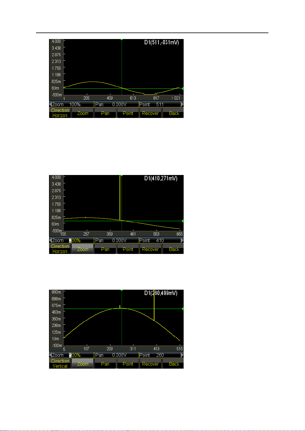
Press 〖Direction〗key and select Horizon. Press 〖Point〗key and set the horizontal
coordinate to be 410. Generator will horizontally zoom as the center of point. Press
〖Zoom〗and set the zoom ratio to be 200%. The waveform point (400, 4.000V) is
displayed. Continue to increase the zoom ratio to 500%, you will see the points
clearer:
(4) Vertical Zoom: Press 〖Point〗key and set the horizontal coordinate to be 260.
Generator will vertically zoom as the center of point. Press〖Zoom〗and set the zoom
ratio to be 500%. The waveform point (250, 550mV) is displayed.
49
Page 50
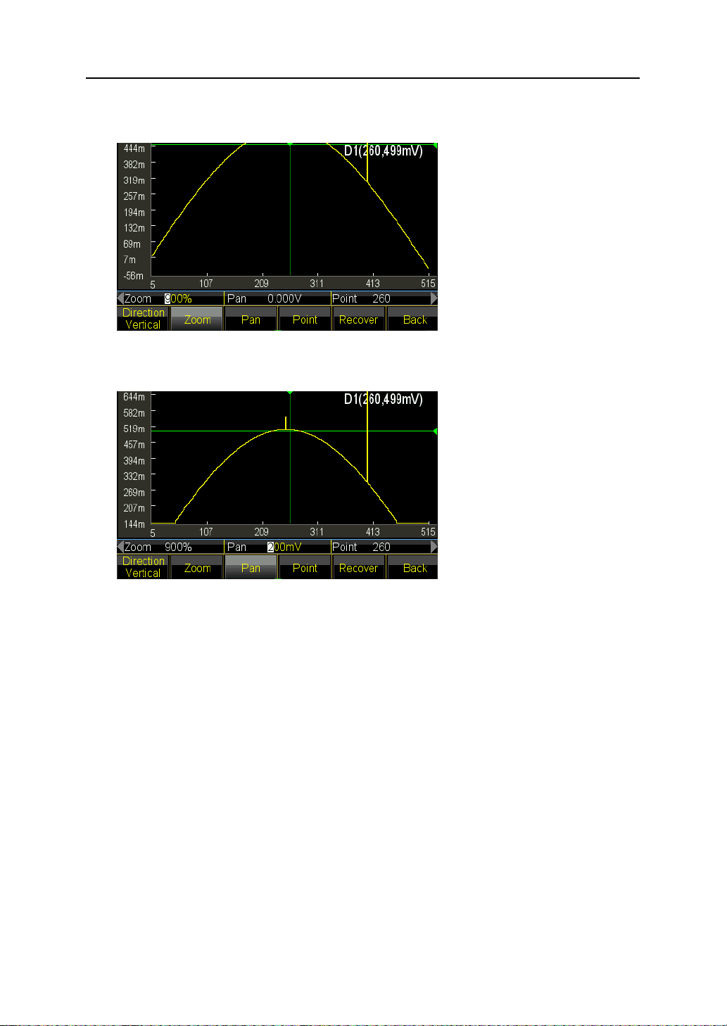
Continue to increase the zoom ratio to 900%, the point is overflow the window and
can’t be seen:
Press〖Pan〗option and set Pan to be 200mVdc, the whole waveform move to down
and you will observe the point (250, 550mV) again.
(5) Press 〖 Recover〗 to back for the initial parameters and display the original
waveform.
5.15.8 Store Waveforms
Generator allows user to save the current editing waveform to user-defined waveform,
which is convenient for user to recall and use the editing waveform even exit of the
editing function. It supplies 7 user-defined waveforms (User_arb (*), *=1, 2, 3…). The
following steps show how to save the current editing waveform to user defined
waveform.
(1) Press 〖Advance〗key to enter into setting menu.
(2) Press 〖User〗key and select waveform from 7 user defined waveforms. If selected
waveform is existing, it will be substituted by new one.
(3) Press 〖Return〗and back to advance setting, Press 〖Return〗key again to other
function window.
(4) Use the stored user defined waveform. User defined waveform can be selected from
built-in waveforms, please refer to Insert Built-in Waveform.
50
Page 51

5.15.9 Recall and Save Arbitrary Waveform
(1) Recall the saved waveform: press 〖Stored Wave〗key to enter into the file manager
and select the file with “*.arb” extension. Then recall it as the method introduction in
chapter 5.15.8,
(2) Recall the arbitrary waveform: new created arbitrary waveform can be saved in
non-volatile memory. Press 〖Store〗key to enter into the file manager and save it,
which will be saved as the extension “*.arb”, the method introduced in chapter
5.16.8.
Note: during the editing, any other function key pressing will exit the editing function and
the editing data will be lost, generator returns to the state before editing. Pay attention to
save the arbitrary waveform data with the reference to Store Waveform.
5.15.10 Arbitrary Operation
User can change the sampling rate, waveform length, amplitude and offset of arbitrary
during the creating of which.
Set sampling rate: press 〖Sample Rate〗key and set it by numeric key or knob within the
range from 1uSa/s to 125MSa/s. frequency is decided both by sampling rate and
arbitrary points, three parameters of which should follow the relationship:
Output Frequency=Sampling Rate * Waveform Length
Set waveform length: waveform length defines the actual sweep points, different from the
point in editing. Press〖Waveform Length〗and set it by numeric keys or knob within the
range from 1 to limited points. If the output waveform differ from the displayed waveform
after the editing operation including point insert, block copy, block cut, user need to
modify the parameters to output desired point.
Set Amplitude and Offset: the setting of amplitude and offset is same as the normal
operation to general waveforms.
5.15.11 Harmonic Waveform
As Fourier Transform theory tells, any periodic function can be decomposed to several
Sine function with different frequencies, amplitudes and phases. On the other hand, we
also can synthesize several Sine wave with different frequencies, amplitudes and phases
to a periodic arbitrary waveform. By this method, user can well analog the distorted
waveform in real life and supply the ideal signal source to testing device.
Our generator can make use of 2 to 50 harmonics to synthesize the arbitrary waveform,
each of them can be set independently the harmonic times, phase and amplitude. Press
51
Page 52

【Waveform】key and then〖Arb〗key, at last〖Harmonic〗key to enter into the synthesis
window.
(1) Harmonic Times: it defines as the multiple of harmonic frequency to fundamental
frequency, so the parameter should be the positive integer within 50. When
harmonic time set as 1, harmonic frequency is fundamental frequency. It can be set
as practical need, several times or even no fundamental and no order for times.
(2) Harmonic Phase: it defines the phase difference between the start points of
harmonic and fundamental wave with reference to a period 360° of fundamental.
(3) Harmonic Amplitude: it defines the percentage that harmonic amplitude occupied in
the full amplitude range of synthesizer. In limited condition, at a certain point, each
harmonic amplitude adds as full range, so the sum of amplitude should be less than
100%. But practice is different, for same point, different harmonic amplitudes are
possible offset by each other. So the sum of harmonic amplitude maybe larger than
100%. Once the final synthesized waveform get out of the full amplitude, it will
produce the limited amplitude, User should make decision as practical need and
less the amplitude of fundamental or some harmonics; If amplitude set as 0, the
harmonic will be canceled.
Press 〖Harmonic Order〗key to set the three parameters. When complete the setting,
press 〖Execute〗key to synthesize the arbitrary waveform on basis of harmonics and
show it on the window. The more times harmonics you set, the longer time for synthesis
procedure needs.
When power off, the harmonic synthesis data will be lost. So press〖Save〗key to store
this harmonic wave to the “User_harmo” memory in〖Special Wave〗of〖Built-in Wave〗,
which allows to be recalled.
The example shows how to synthesize a arbitrary waveform by fundamental and its 3
harmonics.
(1) Press〖Harmonic Order〗key and set it to be 1.
(2) Press〖Harmonic Time〗key and set it to be 1.
(3) Default setting for〖Harmonic Phase〗is 0, no need change.
(4) Press〖Harmonic Amplitude〗key and set it to be 50.00%.
(5) Press〖Harmonic Order〗key and set it to be 2.
(6) Press〖Harmonic Time〗key and set it to be 3.
(7) Default setting for〖Harmonic Phase〗is 0, no need change.
52
Page 53
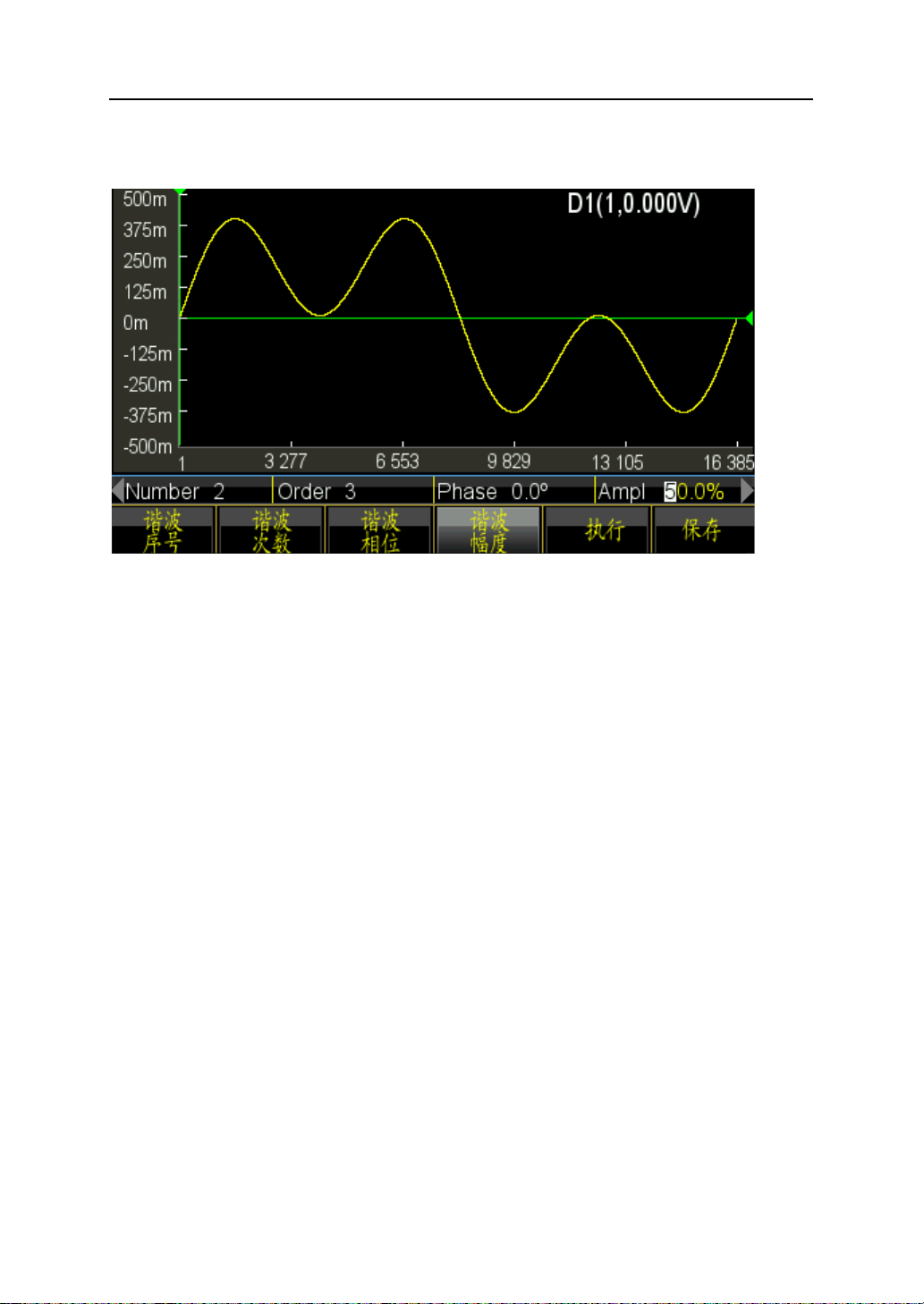
(8) Press〖Harmonic Amplitude〗key and set it to be 50.00%.
(9) Press〖Execute〗key. The synthesized waveform will be shown after a while.
5.16 System Configuration
Press 【Utility】key to set the items like Language, Sync Output, Interface, Power Off
State, Display/Beep, System Resume, Storage, Recall, Calibration and System Update.
5.16.1 Language
Press 〖Language〗softkey to choose Chinese language or English language. The
selection is available for operate menu and prompt information.
5.16.2 Sync Output
Press 〖SYNC〗softkey to enable of disable the sync output.
5.16.3 Interface
Press〖Interface〗to enter into the setting menu, which have〖Network〗and〖Return〗
two options. Press〖Network〗key and set the DHCP, IP address, Subnet Mask, Default
Gateway and Return.
Press〖DHCP〗key to set DHCP on or off. If DHCP is on, user can not set the IP, Subnet
Mask and Default Gateway.
Press〖IP Addr〗key to set IP address by numeric keys.
Press〖Subnet Mask〗key to set subnet mask by numeric keys.
Press〖Default Gateway〗key to set Default Gateway by numeric keys.
Press〖Return〗key to go back to last level menu, and press〖Confirm〗to enable the
setting.
53
Page 54
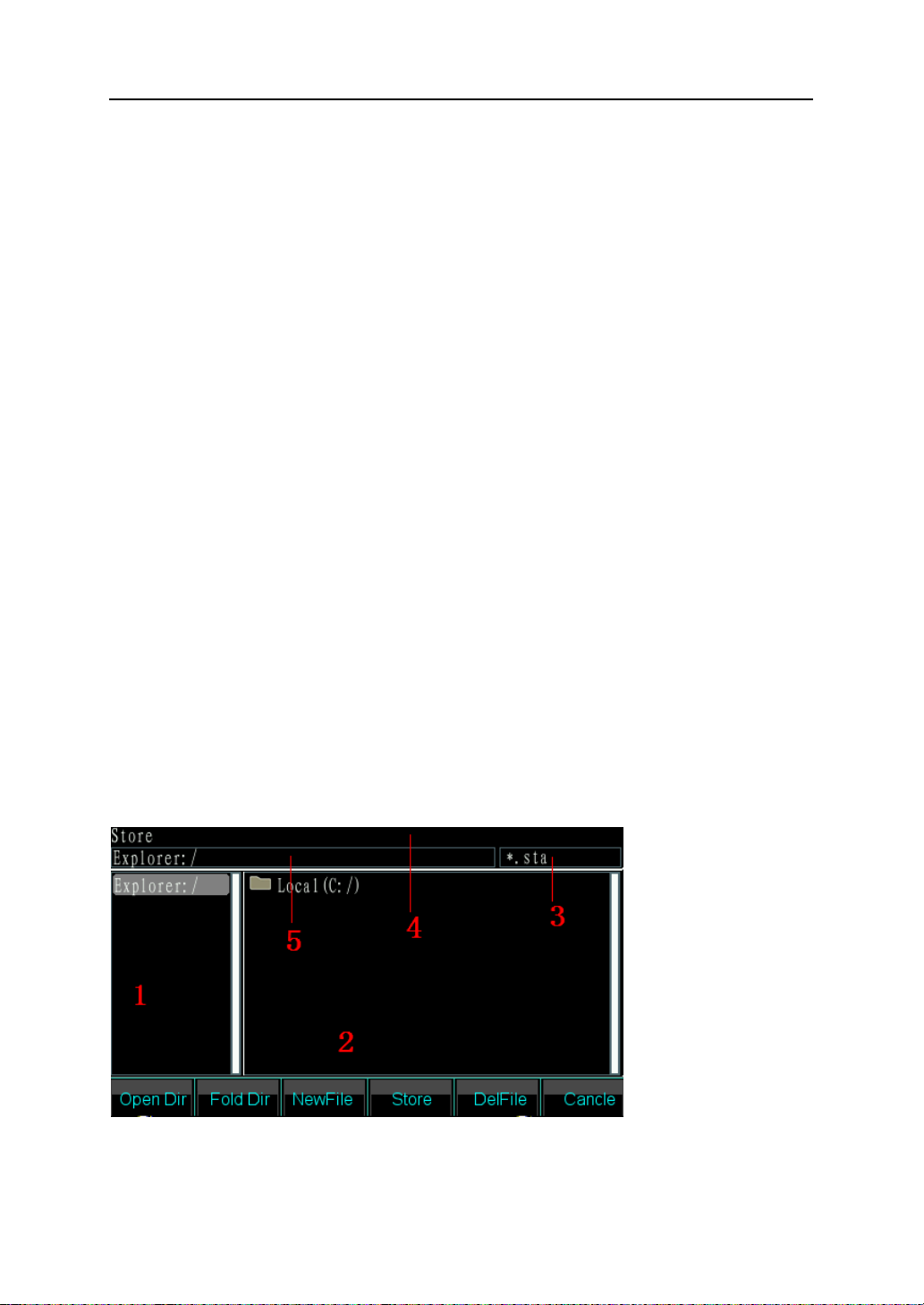
5.16.4 Power-on State
Press 〖Power on State〗softkey and select “Last” option, generator will automatically
recall the last setting that before power off when next power on. For specified conditions,
user can set the power-on state as Last to reduce the repeated operation every time they
turn on the generator. Once select “Default”, the generator will recall the default state at
power-on.
5.16.5 Display/Beep
Press〖Display/Sound〗softkey to enter into the setting menu.
Press〖Screensaver〗key to set the screensaver on or off. If set on, the generator will
enter into the screen protection at 2 minutes.
Press〖Brightness〗key to set the backlight of screen.
Press 〖Key Beep〗 key to enable or disable the beep for key pressing. Even if set the
beep off, once the setting out of range, generator also gives a warning with long blew.
The key pressing beep is only a short prompt tone.
Press〖Display〗key to select display channel. If select single channel display, the graph
displaying area will show current output sketch. If select dual channel, the graph area will
be off and show the dual channel parameters. User also can set the independent
channel parameter, just press the〖CHA/CHB〗to switch the channel.
5.16.6 System Reset
Press〖System Reset〗, generator will return to the system default setting.
5.16.7 Store
Press〖Store〗key to enter into the file manager.
54
Page 55

File Manager:
(1) Current Directory Area: to display current opened directory, that is the upper
directory of sub-directory display area.
(2) Sub-directory Area: to display the sub-directory of current directory and the file
comply with the type.
(3) Type of operated file: to indicate the required file type to accomplish the operation
(*.sta, *.arb, *.exe).
(4) Current operation: to indicate the use of current opened file manager such as State
Operation ( State Store and Recall, *.sta), Arbitrary Operation (Arbitrary Store and
Recall, *.arb), Program Update (*.exe).
(5) Current File Path: to indicate current operation directory of selected file.
Operation:
Select between directory and sub-directory by left/right key.
(1) Open directory: press right key to move the cursor to sub-directory area, then use
up/down key to select the file you want to open. Press〖Open〗to show the next
directories and files whose type meets with the operation requirement.
(2) Fold directory: press left key to move the cursor to parent directory area, then select
〖Fold〗option to fold current directory.
(3) File name typing: if user want to create a new file that accords with the operation
type, press〖File Name〗to enter desired numbers and letters.〖Capital/Lower〗key
to switch between the capital letter and lowercase typing, arrow keys or knob to
select letters and finally〖Select〗to confirm the typing letters. If make wrong type,
user can press〖Delete〗to delete the wrong letter. When finish file name, press
〖Finish〗to save the file. Generator will add the right suffix behind the file name.
Press〖Cancel〗to exit the typing.
(4) Press〖Store〗key to save the selected file.
(5) Press〖Delete〗key to delete stored file.
5.16.8 Recall
Press〖Recall〗softkey to recall the file introduced in chapter 5.16.7.
5.16.9 System Update
Use this function to update the application firmware, which should be operated through
USB interface. Before update, please format the U-disk first to ensure that there is no
other file in.
55
Page 56

The following step will show you how to update:
(1) At power on, place the U-disk on USB device port, generator will identify it
automatically and prompt a “Di” sound once it successfully connected.
(2) Press〖Utility〗softkey to enter into the utility interface. Press〖System Update〗key
and input the password 0.-123456 to enter into the file manager.
(3) Select Removable Disk A in manager and .exe file. The further operation refers to
chapter 5.16.8. Then select〖System Update〗to pop up the confirm window. If you
select confirm, the generator will start updating and then restart with new firmware.
If you select cancel, the generator will exit and operate with original firmware.
(4) Note: make sure that the updating always at power on, once cut off the power, the
generator will fail to update and restart, which need to return to factory for repair.
5.17 Frequency Counter
Press 【Counter】key to enter into counter menu.
Connect the external measured signal to ‘Counter’ connector on rear panel, then to
measure the frequency, period, pulse width and duty cycle of measured signal.
5.17.1 Continuous Signal
The waveform generator can measure the frequency, period, pulse width and duty cycle
of measured continuous signal. Use multi-cycle measurement when high frequency to
get a accurate result.
Press 〖Freq〗softkey then select ‘Frequency’ to measure frequency of measured signal.
Press 〖Period〗softkey then select ‘Period’ to measure period of measured signal.
Press 〖Width〗softkey then select ‘Width’ to measure pulse width of measured signal.
Press 〖Duty Cyc〗softkey then select ‘Duty Cyc’ to measure duty cycle of measured
signal.
5.17.2 Non-continuous Signal
Non-continuous signal, take a burst signal for example, is not available for the
measurement of frequency, period, pulse width and duty cycle but only for measurement
of cycle number.
Press 〖Count On/Off〗softkey then select ‘On’ to enable the counter. Firstly clear the
count value then totalize count begins. Select ‘Off’ to disable the counter. To get a
accurate measurement, turn counter off when disable the input signal.
Once turn on counter, the setting of gate time is ignored.
56
Page 57

5.17.3 Gate Time
Press 〖Gate Time〗softkey then select ‘Gate Time’ to configure the desired gate time.
The gate time indicates the sampling interval time of tested signal, the longer the gate
time is, the more the sampling data, so the users may get more stable measurement
result and higher measurement resolution. And the shorter the gate time is, the better the
tested signal is tracked, but short gate time will result in low measurement resolution.
Generally, gate time should be longer than the period of tested signal.
5.17.4 Trigger Level
Press 〖Trig level〗softkey then select ‘Trig levl’ to configure the desired trigger level
value. Set the trigger level to be 0 if using AC coupling and adjust the trigger level if using
DC coupling. The influence for trigger level adjustment is small if the amplitude of tested
signal is higher. But if the amplitude of measured signal is lower or frequency is higher,
you need adjust the trigger level carefully to get a better result.
5.17.5 Sensitivity
Press 〖Sensitiv〗softkey then select ‘Sensitive’ to configure the desired sensitivity value.
The bigger the value is, the higher the sensitivity is. The influence for sensitivity
adjustment is small if the amplitude of tested signal is higher. But if the amplitude of
measured signal is lower and noise contained in signal, you need adjust the sensitivity to
get a better result.
Generally speaking, improve sensitivity if test value of frequency is less than standard
frequency of measured signal, or lower sensitivity if test value of frequency is greater
than standard frequency of measured signal.
5.17.6 Coupling Mode
Press 〖Coupled〗softkey to choose between AC or DC. If frequency of measured signal
is higher with DC offset, select AC mode and set the trigger level to be 0. If frequency of
measured signal is lower than 1Hz or amplitude lower than 100mVpp, select DC mode
and adjust trigger level properly to get a better result.
5.17.7 Low-pass Filter
Press 〖Filter On/Off〗softkey to turn on or off the low-pass filter. When frequency of
measured signal is lower with high-frequency noise, frequency testing value will be
greater than standard frequency value of test signal, low-pass filter should be turned on
to filter the high-frequency noise, then get an accurate result. But when frequency of
measured signal is higher with lower amplitude, the low-pass filter will attenuate the
57
Page 58

high-frequency signal and frequency testing value will be less than standard frequency
value of test signal even can’t get a result, low-pass filter should be turned off. The upper
limit frequency of low-pass filter will be around 50kHz.
5.18 Input/Output Port
The output port is not allowed using as input s port, or the waveform generator will be
damaged. Clock Input port is isolated with case and other ports, also other ports such as
Output port, Sync Output Port, Modulate Input are isolated with case.
5.18.1 CHA output port
Locate in front panel and the signal of CHA output from this port. Press【Output】key
circularly to enable or disable the signal from CHA port. The indicator on the top of CHA
port light on or off to tell you whether the port is enable or disable.
5.18.2 CHB output port
Same as CHA port and won’t introduce in detail.
5.18.3 Synchronous output port
Locate at front panel. Press 【Utility】key then to 〖Sync On/Off〗softkey to enable or
disable the sync output. The indicator at top of port lights on if user enables the sync port.
The indicator light off if user disables the sync port.
The synchronous output signal is a pulse signal with TTL compatible. The characteristic
will be different under working mode changing, introduce as below,
(1) If select CHA under continuous mode, frequency of sync signal is same as signal
from CHA port, but phase lag to CHA’s. The phase difference can be set on phase
setting of CHA.
CHB under continuous mode is same as CHA.
(2) Under FM, AM, PM, PWM and Sum mode, the duty cycle of sync signal is 50%, the
frequency of sync signal is same as frequency of modulating waveform and the
phase of sync signal are relative with phase of modulating waveform.
(3) Under FSK, QFSK, 4FSK mode, the duty cycle of sync signal is 50%, frequency of
sync signal equals to hop rate. The sync signal is low level when outputting carrier
frequency and high level when outputting hop frequency.
(4) Under PSK, QPASK, 4PSK mode, the duty cycle of sync signal is 50%, frequency of
sync signal equals to hop rate. The sync signal is low level when outputting carrier
phase and high level when outputting hop phase.
58
Page 59

(5) Under ASK mode, the duty cycle of sync signal is 50%, frequency of sync signal
equals to hop rate. The sync signal is low level when outputting carrier amplitude,
and high level when outputting hop amplitude.
(6) Under OSK mode, the duty cycle of sync signal is 50%, frequency of sync signal
equals to hop rate. The sync signal is low level when outputting carrier amplitude,
and high level when outputting hop amplitude.
(7) Under frequency sweep mode, the period of sync signal equals to total time of sweep
process. The rise edge corresponding to start frequency point and falling edge
corresponding to marker frequency point.
(8) Under list sweep mode, the duty cycle of sync signal is 50%, period of sync signal
equals to total sweep time and rise edge of sync signal corresponding to start
number.
(9) Under burst mode, period of sync signal equals to burst period, the rise edge
corresponding to start point of burst signal and fall edge corresponding to stop point
of burst signal. Sync signal is high level if enable burst signal but low level if disable
burst signal.
(10) Under FSK, QFSK, 4FSK, PSK, QPSK, 4PSK, ASK, OSK, frequency sweep, list
sweep and burst output mode, the frequency of sync signal will determined by trigger
signal if external or manual trigger is selected.
5.18.4 Clock Output Port ‘10MHz Out’
Locate in rear panel and output 10MHz clock signal, which can be used external clock for
other device, isolating to case.
5.18.5 Clock Input Port ‘10MHz In’
Locate at rear panel and can be inputted external clock signal to make the generator
synchronized with other device, also can take the higher accuracy frequency standard as
the clock.
5.18.6 Counter Input Port ‘Counter’
Locate at rear panel and can be inputted test signal.
5.18.7 Modulation In/Trigger In/Out Port ‘Trig In/OUT Mod In’
Locate at rear panel and both of input/output ort, can work at input state and output state.
When outputs internal trigger signal, input function is disabled. Input external modulating
signal under FM, AM, PM, PWM and Sum mode. Input external trigger signal under FSK,
59
Page 60

PSK, ASK, OSK modulating modes, frequency sweep, list sweep and burst modes. Also
can output internal trigger signal under frequency sweep, list sweep, burst output mode.
5.19 Communication Port
5.19.1 USB Host
This connector is provided on front panel, which is used to insert U-disk to store and
recall the user-defined waveforms or instrument state, or used for system update.
5.19.2 USB Device
The USB Device connector is provided on rear panel, which be connected with PC using
USB cable to remote control the instrument, or download the user-defined waveform with
waveform edit software, or update the instrument using firmware updating software. For
detail instruction, please refer to CD.
5.19.3 LAN Port
The LAN Port is provided on rear panel, which be connected with PC to remote control
for the instrument. For detail instruction, please refer to CD.
5.20 Calibration
The waveform generator is secured when shipped from factory. After a long time
operating, some parameters are possible have a change. To guarantee the accuracy,
periodical calibration is needed. It’s no necessary to open case for calibration but just
using keypad.
Professional staffs are required for calibration work and calibration used instruments
must comply with the accuracy requirements. When calibrating, the instrument needs to
be warmed up more than 30 minutes and the environments should be meet the
specification required.
When power off, the generator will automatically recall the calibration code stored on last
time. Turning off the calibration is used to prevent the calibration code to be modified.
5.20.1 Enable Calibration
Press 【Utility】key then to 〖Calibrate〗softkey.
Press〖Password〗key then enter calibration code. Press〖Finish〗to enter into calibration
window. User can make calibration to frequency, offset, amplitude, flatness, offset level
and trigger level of counter, the relationship among offset, amplitude and flatness
separately by knob, numeric keys and Last Page/Next Page.
60
Page 61

5.20.2 Channel Selection
Press 〖Cal Channel〗softkey to cycle through calibration channel. If ‘Channel A’ is
displayed, user can calibrate for CHA. If ‘Channel B’ is displayed, user can calibrate for
CHB.
5.20.3 Frequency Calibration
After channel selected, press〖Freq Cal〗softkey to enter into frequency calibration
window. Then press〖Cal Value〗key and set it by knob or numeric keys, to make the
frequency as close to 1MHz as possible. Finally press〖Finish〗key to exit the calibration.
5.20.4 Offset Calibration
Press 〖Offs Cal〗softkey to enter into offset calibration window. Connect generator with
digital multimeter, adjust the calibration value to make the signal offset as the target
value according to calibration instruction. Press〖Next〗key or input calibration value to
enter into the next point calibration. Go on the next standard points calibration like this,
finally press 〖Finish〗key to exit the calibration.
5.20.5 Amplitude Calibration
Press 〖Ampl Cal〗softkey to enter into amplitude calibration window. Then adjust the
calibration value to make the signal output amplitude as the target value according to
calibration instruction. Press 〖Next〗key or input calibration value to enter into the next
point calibration. Go on the next standard points calibration like this, finally press
〖Finish〗key to exit the calibration.
5.20.6 Flatness Calibration
The amplitude of output signal will decrease as the frequency increasing. Therefore, you
need to calibrate for different frequency points. Amplitude flatness uses the relative
comparison method and makes the amplitude with 1MHz frequency as comparison
standard. The calibration includes 3 parts, nominal amplitude of which is 4dBm, 17.96
dBm and 11.93dBm. The step is 5MHz for output signal frequency.
Press〖Flat Cal〗softkey to enter into flatness calibration window.
(1) Calibration sequence display as 0#. Now the generator output 1MHz frequency,
4dBm amplitude reference signal. Measure the actual output amplitude by spectrum
analyzer, the result of which is taken as the first reference value. Press〖Next〗key
and sequence still shows 0#. Adjust calibration value to make the output amplitude
equals to the reference value. Go on the operation like this until the first section
flatness calibration finishes. (0# ~ 31#).
61
Page 62

(2) The second and third section of calibration is same as the first section.
5.20.7 Counter Offset Calibration
Press 〖Count Cal〗softkey to enter into counter offset calibration window. Test the TP49
point on mainboard by using of DC multimeter. Then adjust the calibration value to make
the voltage on 0# of point TP49 as 0.5Vdc. Finally press 〖Finish〗key to exit the
calibration. (Please note that this calibration needs to open the case, if counter works
normal, you don’t have to calibrate it).
5.20.8 Trigger Level Calibration
Press〖Trig Level Cal〗softkey to enter into trigger level calibration window. Test the TP55
point on mainboard by using of DC multimeter. Then adjust the calibration value to make
the TP55 voltage on 0# as 0Vdc and on 1# as 0.5Vdc. Finally press 〖Finish〗key to exit
the calibration. (Please note that this calibration needs to open the case, if counter works
normal, you don’t have to calibrate it).
5.20.9 Store Calibration Value
User must store the calibration value after finishing the calibration, for it would be lost
once power-off. Press〖Cal Store〗key to save the data to non-volatile memory. Generator
exit the calibration after storage.
5.20.10 Recall Calibration Value
Press〖Cal Recall〗softkey then screen prompts inquiry “Back to factory calibration
setting?”. Press〖Default〗to select default calibration data. Press〖Finish〗to enable the
recalling. Press〖Cancel〗to exit the recalling.
When power on, the waveform generator will recall automatically the value from〖User
Value〗memory and applied to it.
5.20.11 Exit Calibration
If you select the other mode during the calibration process, the instrument will remain the
state of last calibration. If the state is not you want, press〖Exit〗softkey, the waveform
generator will resume the state of power on.
5.21 System Reset
Press 【Utility】key then to 〖Reset〗softkey to recall the default setting value.
5.22 Default Setting
62
Page 63

Waveform
Sine
Duty Cycle of Square
50%
Frequency
1kHz
Symmetry of Ramp
50%
Amplitude
1Vpp
Pulse Width
500μs
DC Offset
0Vdc
High Level Limitation
10Vdc
Output Phase
0°
Low Level Limitation
-10Vdc
Output Polarity
Normal
Output Port
Off
External Load
High Z
Frequency Difference
600Hz
Sum Frequency
100Hz
AM Depth
100%
Modulating Frequency
100Hz
Phase Difference
90°
Modulating Waveform
Sine
Pulse Width Difference
50%
Modulating Source
Internal
Sum Amplitude
20%
Hop Frequency
(FSK)
200Hz
Hop Phase (PSK)
180°
Hop Frequency
(QFSK, 4FSK)
Hop Freq 1: 200Hz
Hop Freq 2: 5.0Hz
Hop Freq 3: 400Hz
Hop Phase
(QPSK, 4PSK)
Hop Phase 1:180°
Hop Phase 2:45°
Hop Phase 3:90°
Hop Time
1.0ms
Hop Amplitude
0.5Vpp
Hop Rate (FSK,
QFSK, 4FSK)
100Hz
Hop Rate (PSK,
QPSK, 4PSK)
500Hz
Hop Rate (ASK,
OSK)
100Hz
Modulating
Source
Internal
Start Frequency
100Hz
Sweep Time
3s
Stop Frequency
1kHz
Hold Time
0s
Marker Frequency
550Hz
Return Time
0s
Sweep Mode
Linear
Interval Time
1ms
Trigger Source
Immediate
Start Number
1#
Hold Time
0ms
Stop Number
21#
Trigger Source
Immediate
Stop Time
1s
Burst Mode
Triggered
Trigger Source
Internal
Burst Period
10ms
Burst Count
3cyc
Start Phase
0°
5.22.1 Continuous Output
5.22.2 Modulation Output (FM, AM, PM, PWM and Sum)
5.22.3 Modulating Output (FSK, QFSK, 4FSK, PSK, QPSK, 4PSK, ASK and OSK)
5.22.4 Frequency Sweep
5.22.5 List Sweep
5.22.6 Burst Output
63
Page 64

Frequency Coupling
Off
Frequency Ration
1
Amplitude Coupling
Off
Frequency Difference
0Hz
Waveform Combine
Off
Amplitude Difference
0Vpp
Combine Depth
50%
Offset Difference
0Vdc
Beeper
On
Power-on State
Default
Display Mode
Single CH
Screen saver
Off
Error Queue
Clear
Calibration State
Closed
Brightness
50%
DHCP
Off
5.22.7 Dual Channel Operation
5.25.8 System Configuration
5.23 Power Amplifier
The power amplifier is always built-in the PeakTech 4046. ‘Amplifier In’ in rear panel is
input connector of power amplifier and ‘Amplifier Out’ is output connector of power
amplifier.
Connect the input signal to ‘Amplifier In’ connector, then amplified signal can be obtained
at the connector of ‘Amplifier Out’. The input signal can be the output signal of this
instrument or other device’s.
Please refer to the amplifier specification on page 70.
5.23.1 Input Waveform
Sine. For other waveforms, the distortion will be greater.
5.23.2 Input voltage
The multiple of the power amplifier is double and the maximum output amplitude is
10Vrms. So the maximum input amplitude should be limited within 5Vrms. The output
signal will be distorted beyond the limitation.
5.23.3 Frequency range
The frequency range of the power amplifier is 1Hz to 150kHz. Within the range, the
distortion of Sine is better than 1% and the maximum frequency can reach to 200kHz.
64
Page 65

5.26.4 Output power
The expression of power for the power amplifier is
P = V 2 / R
Where, P is the output power (the unit is W), V is the output virtual amplitude value (the
unit is Vrms), R is the load resistance(the unit is Ω).
The maximum output amplitude can reach 10Vrms and the minimum load resistance can
be 2Ω. Besides, the higher the temperature of the working environment, the larger is the
frequency of the output signal and the greater the distortion of the output signal. Usually,
the maximum output power can reach 8W (8Ω) or 2W (50Ω).
5.23.5 Output protection
The power amplifier is of short circuit protection function and over heat protection.
Usually it is unable to be destroyed but long time output short circuit should be avoided.
The frequency, amplitude and loading should be best within the limitation, two of which,
especially, cannot get the limitation at the same time in case that the power amplifier is
damaged.
6. Maintenance & fuse replacement
In the case of an electrical defect the melting fuse on the rear side (6) of the
device may trigger.
If this is the case, use only a fuse with the same ratings (T 3A/250V 5x20mm) for
replacement.
In normal operation mode the fuse should never trigger without any reasons, so
make sure the electrical defect is eliminated before restarting the device.
Note: The repair must be performed only by qualified personnel.
65
Page 66

7.Specifications
7.1 Continuous Output (CHA&CHB)
7.1.1 Waveform
Standard Waveforms: Sine, Square, Ramp, Pulse, Noise
Built-in Waveforms: 137 waveforms including PRBS (Pseudorandom Binary
Sequence), Exponential Fall, Exponential Rise, Logarithm, Sinc,
Gaussian, Cardiac, Tangent, Semi-Circle, Quake, etc.
User-defined Arbitrary: 7
User-defined Harmonic: 1 (Max. 50 times, amplitude and phase adjustable)
Sampling Rate: 500MSa/s
Vertical Resolution: 14bits
7.1.2 Sine
Harmonic distortion (0dBm): ≤-60dBc Frequency<10MHz
≤-55dBc Frequency<80MHz
≤-50dBc Frequency<100MHz
≤-45dBc Frequency≥100MHz
Total Distortion (20Hz to 20kHz, 20Vpp): ≤0.1%
7.1.3 Square, Pulse and Ramp
Duty Cycle of Square/Pulse: 0.1% to 99.9%
(minimum Pos width and Neg width of Square is 10ns)
Overshoot of Square/Pulse (Typical Value): ≤ 5%
Edge time of Square (1Vpp): ≤8ns
Edge time of Pulse (1Vpp): 4ns to 100us
Pulse Width: 10ns to 1000s
Symmetry of Ramp: 0.0% to 100.0%
7.1.4 Arbitrary Waveform
Waveform Length: 6 to 1M points
Sample Rate: 1uSa/s to 125MSa/s, 1uSa/s Resolution
Amplitude Resolution: 14bits
7.1.5 Frequency
Frequency Range:
Sine: 1μHz to 160MHz (see note)
Square and Pulse: 1μHz to 50MHz (see note)
66
Page 67

Ramp: 1μHz to 5MHz
Other waveforms: 1μHz to 30MHz
Frequency Resolution: 1μHz
Frequency Accuracy: ±(2ppm+1μHz)
7.1.6 Amplitude (offset 0Vdc)
Amplitude Range:
2mVpp to 20Vpp (open circuit), 1mVpp to 10Vpp (50Ω) Frequency≤40MHz
2mVpp to 10Vpp (open circuit), 1mVpp to 5Vpp (50Ω) Frequency≤80MHz
2mVpp to 5Vpp (open circuit), 1mVpp to 2.5Vpp (50Ω) Frequency≤120MHz
2mVpp to 4Vpp (open circuit), 1mVpp to 2Vpp (50Ω) Frequency>120MHz
Amplitude Resolution:
2mVpp (Amplitude≥2Vpp, open circuit), 1mVpp (Amplitude≥1Vpp, 50Ω)
0.2mVpp (Amplitude<2Vpp, open circuit), 0.1mVpp (Amplitude<1Vpp, 50Ω)
Amplitude Accuracy (1kHz Sine, 0V offset, auto range):
±(setting value×1%+2mVpp)
Amplitude Flatness (compared to 1MHz Sine):
±0.1dBm frequency<10MHz
±0.2dBm frequency<80MHz
±0.3dBm frequency≥120MHz
Amplitude Unit (Sine): Vpp, Vrms and dBm
7.1.7 Offset
Offset Range: ±5Vpk ac + dc (50Ω)
±10Vpk ac + dc (open-circuit)
Offset Resolution: 1mVdc (offset≥0.5Vdc, 50Ω)
0.1mVdc (offset<0.5Vdc, 50Ω)
2mVdc (offset≥1Vdc, open circuit)
0.2mVdc (offset<1Vdc, open circuit)
Offset Accuracy: ±(setting value×1%+2mVdc+amplitude×0.5%)
7.1.8 Polarity and Phase
Output Polarity: positive or negative (relative to the displaying
waveform)
Output Phase: 0°to 360° (compared to sync)
7.1.19 Output Port
67
Page 68

Output Impedance: 50Ω (typical)
Protection: overload automatically disables main output
Connector: connect with the housings of Sync Output, Modulate In, Counter In, Clock
Out, but isolated with case, limited voltage for connector housing is 42Vpk.
7.2 Modulation Output
7.2.1 FM, AM, PM, PWM and Sum Modulation
Carrier Waveforms: Sine, Square, Ramp (only pulse for PWM), etc.
Modulation Waveforms: Sine, Square, Ramp, etc.
Modulating Frequency: 1mHz to 100kHz (FM,AM, PM, PWM)
1mHz to 1MHz (Sum)
Frequency Difference: 0 μHz to half of Max. Frequency
AM Modulating Depth: 0% to 120%
Phase Deviation: 0° to 360°
Pulse Width Deviation: 0% to 99%
Sum amplitude: 0% to 100%
Modulating Source: Internal and External
7.2.2 FSK, 4FSK, QFSK, PSK, 4PSK, QPSK, ASK and OSK
Carrier Waveforms: Sine, Square, Ramp and so on
FSK Frequency: 1μHz to Max. Frequency
Hop Phase: 0° to 360°
Hop Amplitude: 2mVpp to amplitude of carrier
Hop Time: 4ns to 400s
Hop Rate: 1mHz to 1MHz
Modulating Source: Internal/External
7.3 Sweep Characteristics
7.3.1 Sweep Waveform: Sine, Square, Ramp, etc.
7.3.2 Sweep Mode: linear, logarithmic, list sweep of whole range
7.3.3 Sweep Time:
Linear and Logarithmic Sweep:
Sweep Time: 1ms to 500s
Hold Time: 0s to 500s
Return Time: 0s to 500s
Interval Time: 0s to 500s
68
Page 69

List Sweep:
Dwell Time: 1ms to 500s
Hold Time: 0s to 500s
7.3.4 Frequency List Length: 128
7.3.5 Trigger Source: internal, external and manual
7.4 Burst Output
7.4.1 Burst Waveform: Sine, Square, Ramp and etc.
7.4.2 Burst Mode: Triggered, Gated
7.4.3 Burst Period: 1μs to 500s
7.4.4 Burst Count: 1 to 100000000 cycles
7.4.5 Gated Output: More than two complete cycles
7.4.6 Start/Stop Phase: 0°to 360°
7.4.7 Trigger Source: internal, external or manual
7.5 Dual Channels Characteristics
7.5.1 Frequency Coupling: frequency ratio, frequency difference
7.5.2 Amplitude & Offset Coupling: amplitude difference, offset difference
7.5.3 Waveform Combine: combine amplitude: 0% to 100%
7.6 SYNC Output
7.6.1 Waveform Characteristics: TTL compatible, edge time≤10ns
7.6.2 Frequency and Pulse Width: changes as working mode
7.6.3 Output Impedance: 50Ω typical value
7.6.4 Connector Grounded: connect with the housings grounded and isolated with case,
limited voltage for connector housing is ±42Vpk.
7.7 Modulation In and Trigger In/Out
7.7.1 Modulation Input:
Input Voltage: ±2.5Vpp (full scale)
Input Impedance: 10kΩ
7.7.2 Trigger Input:
Input Level: TTL Compatible
Input Impedance: 1kΩ
69
Page 70

7.7. 3 Trigger Output:
Output Level: TTL Compatible
Input Impedance: 1kΩ
7.7.4 Connector: isolated with case, limited voltage for connector housing is
±42Vpk
7.8 Frequency Counter
7.8.1 Frequency Range: 10mHz to 350MHz Resolution: 7 digits/s
7.8.2 Measurement of Period and Pulse-width: 100ns to 20s
7.8.3 Duty Cycle Measurement: 1% to 99%
7.8.4 Count Measurement: 1 to 9999999999
7.8.5 Sensitivity:
20mVrms to 5Vrms 10mHz to 150MHz
40mVrms to 5Vrms 150MHz to 250MHz
100mVrms to 5Vrms 250MHz to 300MHz
200mVrms to 5Vrms 300MHz to 350MHz
7.8.6 Gate Time: 1ms to 100s
7.8.7 Trigger Level: -2.5V to +2.5V
7.8.8 Couple Mode: AC, DC
7.8.9 Low-pass Filter: enable or disable
7.8.9 Connector: isolated with case, limited voltage for connector housing is ±42Vpk
7.9 Communication Port
7.9.1 Interface type: USB Device, USB Host, LAN
7.9.2 Connector: connected with case grounded
7.10 Clock
7.10.1 External Clock Input
Clock Frequency: 10 MHz ±50Hz
Clock Amplitude: 100m Vpp to 5 Vpp
Input Impedance: 300 , AC coupling
Connector: isolated with case and other connectors
7.10.2 Internal Clock Output
Clock Frequency: 10 MHz
70
Page 71

Clock Amplitude: >1 Vpp
Output I , AC coupling
Connector: isolated with case, limited voltage for connector housing is ±42Vpk
7.11 General Characteristics
7.11.1 Power: AC 100 to 240V, 45~65Hz, <30 VA
7.11.2 Environment Condition: Temperature: 0 to 40°C Humidity: <80%
7.11.3 Display: 4.3″ colorful TFT-LCD, 480×272 pixel
7.11.4 Dimensions & Weight: 367×256×106 mm, Approx.3.7 kg
7.12 Power Amplifier
7.12.1 Input signal:
Voltage: 0Vrms to 5Vrms
Frequency: 1Hz to 200kHz
7.12.2 Voltage Amplifier: double
7.12.3 Output Power: 8W (load 8Ω) 2W(load 50Ω) Frequency≤100kHz
3W(load 8Ω) 1W(load 50Ω) Frequency≤200kHz
Note 1: The test of the specifications should be operated under temperature of 18℃ to
28℃, warm up time >30 minutes
Note 2: 4046 Sinewave frequency range: 1μHz~160MHz
Square and Pulse frequency range: 1μHz~50MHz
71
Page 72

All rights, also for translation, reprinting and copy of this manual or parts are reserved.
Reproduction of all kinds (photocopy, microfilm or other) only by written permission of the
publisher.
This manual considers the latest technical knowing. Technical alterations reserved.
We herewith confirm, that the units are calibrated by the factory according to the
specifications as per the technical specifications.
We recommend to calibrate the unit again, after one year.
© PeakTech® 07/2020 EHR.
PeakTech Prüf-und Messtechnik GmbH – Gerstenstieg 4 - DE-22926 Ahrensburg / Germany
+49-(0) 4102-97398 80 +49-(0) 4102-97398 99
info@peaktech.de www.peaktech.de
72
 Loading...