

Page 1

PeakTech
4025 / 4030
Bedienungsanleitung /
Operation Manual
DDS Funktionsgeneratoren /
DDS Function Generators
Page 2

1. Sicherheitshinweise zum Betrieb des Gerätes
Dieses Gerät erfüllt die EU-Bestimmungen 2004/108/EG (elektromagnetische Kompatibilität) und
2006/95/EG (Niederspannung) entsprechend der Festlegung im Nachtrag 2004/22/EG (CE-Zeichen).
Zur Betriebssicherheit des Gerätes und zur Vermeidung von schweren Verletzungen durch Strom- oder
Spannungsüberschläge bzw. Kurzschlüsse sind nachfolgend aufgeführte Sicherheitshinweise zum Betrieb
des Gerätes unbedingt zu beachten.
Schäden, die durch Nichtbeachtung dieser Hinweise entstehen, sind von Ansprüchen jeglicher Art
ausgeschlossen.
* Vor Anschluss des Gerätes an eine Steckdose überprüfen, dass die Spannungseinstellung am Gerät mit
der vorhandenen Netzspannung übereinstimmt
* Gerät nur an Steckdosen mit geerdetem Schutzleiter anschließen
* maximal zulässige Eingangswerte unter keinen Umständen überschreiten
* Defekte Sicherungen nur mit einer dem Originalwert entsprechenden Sicherung ersetzen. Sicherung oder
Sicherungshalter niemals kurzschließen.
* Vor dem Umschalten auf eine andere Messfunktion Prüfleitungen oder Tastkopf von der Messschaltung
abkoppeln.
* Gerät, Prüfleitungen und sonstiges Zubehör vor Inbetriebnahme auf eventuelle Schäden bzw. blanke oder
geknickte Kabel und Drähte überprüfen. Im Zweifelsfalle keine Messungen vornehmen.
* Ventilationsschlitze im Gehäuse unbedingt freihalten (bei Abdeckung Gefahr eines Wärmestaus im
Inneren des Gerätes)
* Keine metallenen Gegenstände durch die Ventilationsschlitze stecken.
* Keine Flüssigkeiten auf dem Gerät abstellen (Kurzschlussgefahr beim Umkippen des Gerätes)
* Gerät nicht auf feuchten oder nassen Untergrund stellen.
* Messspitzen der Prüfleitungen nicht berühren.
* Warnhinweise am Gerät unbedingt beachten.
* Gerät keinen extremen Temperaturen, direkter Sonneneinstrahlung, extremer Luftfeuchtigkeit oder Nässe
aussetzen.
* Starke Erschütterung vermeiden.
* Gerät nicht in der Nähe starker magnetischer Felder (Motoren, Transformatoren usw.) betreiben
* Heiße Lötpistolen aus der unmittelbaren Nähe des Gerätes fernhalten.
* Vor Aufnahme des Messbetriebes sollte das Gerät auf die Umgebungstemperatur stabilisiert sein (wichtig
beim Transport von kalten in warme Räume und umgekehrt)
* Säubern Sie das Gehäuse regelmäßig mit einem feuchten Stofftuch und einem milden Reinigungsmittel.
Benutzen Sie keine ätzenden Scheuermittel.
* Dieses Gerät ist ausschließlich für Innenanwendungen geeignet.
* Nehmen Sie das Gerät nie in Betrieb, wenn es nicht völlig geschlossen ist.
* Vermeiden Sie jegliche Nähe zu explosiven und entflammbaren Stoffen.
* Keine technischen Veränderungen am Gerät vornehmen.
* Öffnen des Gerätes und Wartungs- und Reparaturarbeiten dürfen nur von qualifizierten Service-
Technikern durchgeführt werden.
* Gerät darf nicht unbeaufsichtigt betrieben werden
* -Messgeräte gehören nicht in Kinderhände-
Reinigung des Gerätes:
Vor dem Reinigen des Gerätes, Netzstecker aus der Steckdose ziehen. Gerät nur mit einem feuchten,
fusselfreien Tuch reinigen. Nur handelsübliche Spülmittel verwenden.
Beim Reinigen unbedingt darauf achten, dass keine Flüssigkeit in das Innere des Gerätes gelangt. Dies
könnte zu einem Kurzschluss und zur Zerstörung des Gerätes führen.
-1-
Page 3

2. Einführung PeakTech® DDS-Funktionsgeneratoren
Ausgerüstet mit Direkter Digitalsynthese-Technik bieten PeakTech
DDS Funktionsgeneratoren eine hohe
Leistung sowie vielfältige Funktionen, die für schnelle Messeinsätze nötig sind. Die einfach gestaltete Front,
die numerische Anzeige sowie die Anzeigelampen erlauben komfortables Arbeiten und Ablesen. Darüber
hinaus erweitern zahlreiche optionale Funktionen die Eigenschaften des Gerätes.
2.1. Vorbereitungen zum Betrieb
2.1.1. Prüfen des Messgerätes und des Zubehörs
Prüfen Sie, ob das Messgerät und das Zubehör vollständig und unbeschädigt sind. Bei starker
Beschädigung der Verpackung sollten Sie diese aufbewahren, bis Sie das Messgerät vollständig geprüft
haben.
2.1.2. Funktionsgenerator mit dem Stromnetz verbinden und einschalten
Ein sicherer Betrieb des Gerätes ist nur unter folgenden Bedingungen gewährleistet.
* Spannung: 100-240 VAC
* Frequenz: 50/60 Hz
* Stromaufnahme: < 30 VA
* Temperatur: 0 ~ 40°C
* Feuchte: 80 %
Stecken Sie den Kaltgerätestecker in die Buchse auf der Geräterückseite. Achten Sie auf korrekte Erdung.
Drücken Sie den Hauptschalter an der Gerätefront. Der Generator wird initialisiert und die
Standardparameter eingestellt. Das Gerät geht in folgenden Arbeitsmodus: Einzelfrequenz auf Kanal A,
Sinussignal, Anzeige der Werte für Frequenz und Amplitude von Kanal A.
WARNUNG!
Um die Sicherheit des Bedieners zu gewährleisten, muss das Gerät an eine dreipolige Schutzkontaktsteckdose mit Schutzleiter angeschlossen werden.
-2-
Page 4

2.2. Beschreibung der Gerätefront und der -rückseite
2.2.1. Gerätefront
1.
Anzeige
2. Hauptschalter
3. Wahltasten für Signalform
4. Optionstasten
5. Ausgang A
6. Ausgang B
7. Synchronisation
8. Richtungstasten
9. Einstellknopf
10. Funktionstasten/Zifferntasten
2.2.2. Geräterückseite
USB
T 2A/250V
FM Input
P-Output
P-Input
REPLACE FUSE
AS SPECIFIED
DISCONNECT POWER CORD
BEFORE REPLACING FUSE
Count Input
100-240V AC 50/60H
Z
1. Kaltgerätebuchse
2. Lüfter
3. Externer Modulationseingang
4.
Frequenzmesseingang
5. Verstärkereingang
6.
Verstärkerausgang
7. USB-Anschluss
-3-
1.
2. 3. 4.
5.
6. 7.
8.
9. 10.
2. 3.
4. 5.
6.
1.
7.
Page 5

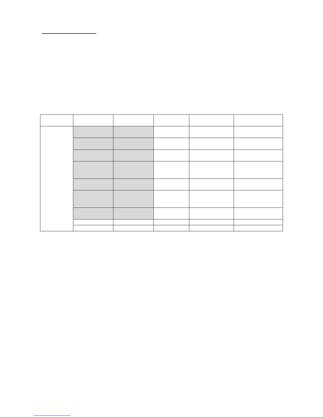
2.3. Anzeige
Die Anzeige ist zweizeilig. Die obere Zeile zeigt zeitbestimmte Werte wie Frequenz, Periode, Intervall,
Torzeit, Frequenzhub, Tastverhältnis und andere an. Die untere Zeile zeigt Spannungsparameter wie
Amplitude, Offset, Dämpfung und andere Parameter wie harmonische Vielfache, Phasendifferenz,
Signalform-ID usw. an. Die Anzeige enthält 22 Anzeigelampen, die die Ausgabekanäle, Signalformen, die
aktuell gewählte Funktion und Optionen sowie Einheiten angeben. Das Gerät besitzt 5 Funktionen mit den
folgenden Optionen. Die in der folgenden Tabelle grau hinterlegten Optionen sind Standardfunktionen, die
direkt durch Drücken der entsprechenden Tasten an der Gerätefront gewählt werden können und die das
Gerät dann automatisch einnimmt. Die Optionen ohne Hintergrund werden weniger häufig gebraucht. Um sie
auszuwählen, müssen Sie zunächst die entsprechende Funktion aufrufen und dann mit Hilfe der Taste
【Menu】 den entsprechenden Eintrag wählen.
2.3.1. Tabelle d er F unktionen
Funktion
Frequenz
Kanal A
Sinus
Frequenz
Kanal B
Sinus
Frequenz-
durchlauf
Frequenz-
modulation
Externe
Frequenz-
messung
Option
Frequenz
Kanal A
Frequenz
Kanal B
Startfrequenz Trägerfrequenz
Externe Frequenz-
messung
Periode
Kanal A
Periode
Kanal B
Endfrequenz Trägeramplitude Torzeit
Amplitude
Kanal A
Amplitude
Kanal B
Frequenz-
schritt
Frequenz-
modulation
Signalform
Kanal A
Signalform
Kanal B
Durchlauf-
modus
Offset der
Frequenz-
modulation
Tastverhältnis
Kanal A
Tastverhältnis
Kanal B
Intervallzeit
Modulations-
signalform
Dämpfung
Kanal A
Dämpfung
Kanal B
Offset
Kanal A
Phasenver-
schiebung
Kanal B
Frequenz-
schritt
Amplituden-
schritt
2.4. Beschreibung der Tasten
Auf der Gerätefront befinden sich 38 Tasten mit folgenden Funktionen (siehe Gerätefront).
* Tasten 【0】 【1】【2】【3】 【4】【5】【6】【7】【 8】 【9】dienen zur Eingabe von Zahlen.
* Taste 【.】 dient zur Eingabe des Dezimalpunkts.
* Taste 【 -】 dient zur Eingabe von Minuswerten in der Option „Offset” sowie in anderen Fällen; auch zum
Einschalten bzw. Ausschalten des Tastendrucktons.
* Die Tasten 【CHA】【CHB】 【Sweep】【 FM】【Count】 dienen zur Auswahl von Funktionen.
* Taste 【Menu】 dient zur Auswahl von Optionen, die in der Tabelle der Funktionen ohne grauen
Hintergrund erscheinen.
* Die Tasten 【Freq】【 Perd】【 Ampl】【Atten】【Offs】【Duty】【Harmo】【Phase】 dienen zur
direkten Auswahl von Optionen, die in der Tabelle der Funktionen auf grauem Hintergrund erscheinen.
* Taste 【pp/rms】 dient zur Auswahl des Spitze-Spitze-Werts und des virtuellen Amplitudenwertes.
* Die Tasten 【 Sine】【 Square】【Triang】 【Ramp】【Arb】 dienen zur Auswahl einer der vier
Grundsignalformen. Drücken Sie die Taste 【Arb】, um eine der 16 Signalformen unter Zuhilfenahme der
Signalform-ID auszuwählen.
-4-
Page 6

* Die fünf Tasten oben haben eine Doppelfunktion. Mit ihnen können Sie auch die Maßeinheiten
【MHz】【 kHz】【Hz】【mHz】【%】 sowie die Signalform-ID 【n】 eingeben. Drücken Sie nach
der Eingabe von Daten eine dieser fünf Tasten, um die Maßeinheit auszuwählen und das Ende der
Dateneingabe zu signalisieren.
* Die Tasten 【∧ 】【∨】 dienen zum Erhöhen oder Verringern der Frequenz oder des Amplitudenschritts
von Kanal A.
* Die Tasten 【< 】【>】 bewegen den Cursor nach links order rechts.
* Die Taste 【Cal. 】 dient zur Kalibrierung der Parameter.
* Mit der Taste 【Reset】 können Sie das System zurücksetzen.
2.5. Allgemeine Bedienung
Die folgende Beschreibung erklärt die allgemeine Bedienung für die Standardnutzung. Bei Fragen lesen Sie
bitte die entsprechenden Abschnitte in Kapitel 3 dieser Anleitung.
2.5.1. Einstellung von Parametern für Kanal A
Drücken Sie die Taste 【CHA】; die Anzeigelampen „CHA” und „Tone” leuchten auf, und das Gerät
befindet sich in der Einzelfrequenz-Funktion von Kanal A.
* Frequenzeinstellung für Kanal A: drücken Sie die folgenden Tasten, um eine Frequenz von 3,5 kHz
einzustellen: 【Freq】【3】【.】 【5】【kHz】.
* Abstimmen der Frequenz für Kanal A: drücken Sie die Taste 【< 】 oder 【> 】, um den Cursor zu
bewegen. Zur Fein- oder Grobabstimmung der Frequenz drehen Sie den Knopf in Uhrzeigerrichtung oder
gegen die Uhrzeigerrichtung, um den Wert stufenlos zu verringern oder zu erhöhen. So können mit diesem
Knopf Werte für andere Optionen eingestellt werden, was nicht erneut erwähnt wird.
* Einstellung der Periode für Kanal A: drücken Sie die folgenden Tasten, um eine Periode von 25 ms
einzustellen 【Perd】【2】【5】【 ms】.
* Einstellung der Amplitude für Kanal A: drücken Sie die folgenden Tasten, um eine Amplitude von 3,2 V
einzustellen: 【Ampl】【3】【.】【 2】 【V】.
* Auswahl des Amplitudenformats von Kanal A: Virtueller Wert oder Effektivwert 【pp/rms】. Die
Anzeigelampe Vpp zeigt an, dass der Amplituden-Effektivwert gewählt wurde. Die Anzeigelampe Vrms
zeigt an, dass der virtuelle Amplitudenwert gewählt wurde.
* Auswahl üblicher Signalformen für Kanal A: Wählen Sie Sinus, Rechteck, Dreieck, Rampe für Kanal A
【Sine】 【Square】【Triang】【 Ramp】.
* Auswahl der Signalform für Kanal A: Wählen Sie Exponentiell für Kanal A (Signalform Nr.12, siehe die
Tabelle der 16 Signalform-IDs auf Seite 11) 【Wave】【1】【 2】【n】.
* Einstellen des Tastverhältnisses für Kanal A: drücken Sie die folgenden Tasten, um ein Tastverhältnis
von 65 % für Kanal A einzustellen 【Duty】【6】【5】【%】 .
* Einstellen der Dämpfung für Kanal A: drücken Sie die folgenden Tasten, um eine feste Dämpfung von 0
dB einzustellen (wählen Sie automatische Dämpfung, AU, nach dem Start oder Reset)
【Atten】【 0】 【dB】
* Einstellen des Offset für Kanal A: drücken Sie die folgenden Tasten, um einen Gleichspannungsoffset
von -1V bei einer Dämpfung von 0 dB einzustellen.
【Offs】【 -】 【1】【 V】.
-5-
Page 7

* Frequenzschritt für Kanal A: So stellen Sie einen Frequenzschritt von 12,5 Hz für Kanal A ein: Drücken
Sie die Taste 【Menu】 und dann die Tasten 【1】【 2】 【•】【5】【Hz】. Die Frequenz von Kanal A
wird bei jedem Druck auf Taste 【∧】 um 12,5 Hz erhöht und bei jedem Druck auf Taste 【∨】 um
12,5 Hz verringert.
2.5.2. Einstellung von Parametern für Kanal B
Drücken Sie die Taste 【CHB】; die Anzeigelampen „CHB” und „Tone” leuchten auf, und das Gerät befindet
sich in der Einzelfrequenz-Funktion von Kanal B. Die Bedienung zum Einstellen von Frequenz, Periode,
Amplitude, Vss, Vrms, Signalform und Tastverhältnis für Kanal B ist identisch mit der für Kanal A.
* Einstellen der harmonischen Signalform für Kanal B: drücken Sie die folgenden Tasten, um die
Frequenz von Kanal B auf die erste Harmonische von Kanal A einzustellen. 【Harm o】【1】【n】
* Phasenverschiebung für Kanal B: drücken Sie die folgenden Tasten, um die Phasenverschiebung
zwischen beiden Kanälen auf 90° einzustellen 【Phase】【 9】 【0】【°】
2.5.3. Frequenzdurchlauf für Kanal A
* Drücken Sie die Taste 【Sweep】. Das Durchlaufsignal wird in Kanal A ausgegeben. Es werden die
Standardparameter verwendet.
* Einstellen des Durchlaufmodus: so stellen Sie den kontinuierlich Richtung wechselnden
Frequenzdurchlauf ein. Drücken Sie die Taste 【Menu】, bis die Anzeigelampe „Sweep“ aufleuchtet und
drücken Sie dann 【2】【n】. Die Einstellung anderer Parameter wird in Abschnitt 4.4. beschrieben.
2.5.4. Frequenzmodulation für Kanal A
* Drücken Sie die Taste 【FM】, um das frequenzmodulierte Signal (FM) in Kanal A auszugeben. Es
werden die Standardparameter verwendet.
* Einstellen des Frequenzhubs: Drücken Sie die folgende Tasten, um einen Frequenzhub von 5%
einzustellen. Drücken Sie die Taste 【Menu】, bis die Anzeigelampe „Devia“ aufleuchtet. Drücken Sie die
Tasten 【5】【 %】 . Die Einstellung anderer Parameter für den Frequenzhub wird in Abschnitt 4.5.
beschrieben.
2.5.5. Zustand nach Initialisierung oder Reset
Das Gerät befindet sich nach dem Start oder nach Drücken der Taste 【reset】 in folgendem Zustand:
* Signalform für Kanal A und B: Sinus
* Frequenz für Kanal A und B: 1 kHz
* Amplitude für Kanal A und B: 1 Vss
* Tastverhältnis von Kanal A und B: 50%
* Dämpfung für Kanal A: AU (automatisch)
* Offset für Kanal A: 0 V
* Harmonische Signalform für Kanal B: 1.0
* Phasenverschiebung für Kanal B: 0°
* Startfrequenz: 500 Hz
* Endfrequenz: 5 kHz
* Frequenzschritt: 10 Hz
* Intervallzeit: 10 ms
* Durchlaufmodus: 0 (positiv)
* Trägerfrequenz: 50 kHz
* Trägeramplitude: 1 Vss
* Frequenzmodulation: 1 kHz
* Frequenzhub: 5,0%
* Modulationssignalform: Sinus
* Torzeit: 1000 ms
-6-
Page 8
3. Funktionsbeschreibung
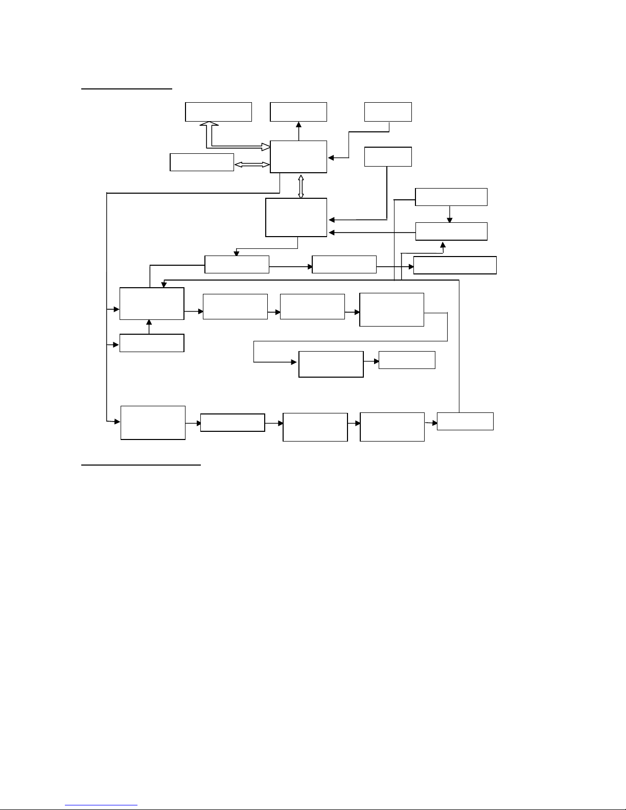
3.1. Blockdiagramm
3.2. DDS-Funktionsprinzip
* Herkömmliche Signalgeneratoren verwenden zur Erzeugung eines Spannungssignals verschiedene
elektronische Oszillatorschaltungen. Die damit erreichbare Frequenzgenauigkeit und Frequenzstabilität ist
nicht hoch genug. Darüber hinaus ist die Technik sehr komplex, die Auflösung gering, die
Frequenzeinstellung unbequem, und die Steuerung durch einen PC schwierig. Die direkte Digitalsynthese
(DDS) ist ein neuartiges Verfahren zur Signalerzeugung ohne Oszillatorkomponenten, das mit Hilfe einer
digitalen Synthese einen Datenstrom erzeugt, aus dem über einen DA-Wandler ein vorher einstellbares
Analogsignal erzeugt wird.
* Zur Erzeugung eines Sinussignals wird zunächst die Funktion y = sinx gequantelt, dann x als Adresse und
y als gequantelte Daten im Signalformspeicher gespeichert. DDS nutzt die Phasenadditionstechnik zur
Ansteuerung des Signalformspeichers. Bei jedem Taktimpuls wird das Phasenergebnis des
Phasenspeichers inkrementiert, so dass die Ausgangsfrequenz analog zur Phasenerhöhung erhöht wird.
Gemäß der Adresse des Phasenspeichers werden die gequantelten Daten aus dem Signalspeicher
entnommen und über DA-Wandler und Operationsverstärker in eine analoge Spannung umgewandelt. Da
die Signalformdaten kontinuierlich abgetastet werden, gibt der DDS-Generator ein getrepptes Sinussignal
aus. Die damit einhergehenden harmonischen Oberwellen werden mit einem Tiefpass gefiltert, um ein
glattes Sinussignal zu erzielen. Die Verwendung einer hochgenauen Referenzspannung in dem DA-
Wandler ermöglicht die Ausgabe eines sehr genauen und stabilen Signals.
* Die Amplitudensteuerung besteht aus einem DA-Wandler. Auf Grundlage des vom Bediener
voreingestellten Amplitudenwerts erzeugt dieser eine entsprechende Analogspannung, die mit dem
Ausgangssignal multipliziert wird und so die Einhaltung des voreingestellten Werts für die Amplitude des
Ausgangssignals garantiert. Die Offsetsteuerung besteht aus einem DA-Wandler. Auf Grundlage des vom
Bediener voreingestellten Offsetwerts erzeugt dieser eine entsprechende Analogspannung, die mit dem
-7-
Keyboar
d
Displayer
Knob
MCU
Digital circuit
Clock
DDS
Modulation input
FM
TTL output
Comparator Lowpass
Amplitude
control
and AM
Offset setting
Voltage
amplification
Power
amplification
Output
attenuation
20-6
0dB
Output A
Output
protection
DDS
Lowpass
Amplitude
control
Power
amplification
Output B
Page 9

Ausgangssignal multipliziert wird und so die Einhaltung des voreingestellten Werts für den Offset des
Ausgangssignals garantiert. Das von der Amplitudensteuerung und der Offsetsteuerung synthetisierte
Signal wird vom Ausgangsverstärker verstärkt und an Ausgang A ausgegeben.
3.3. Bedienkonzept
* Die MPU steuert die Tasten und die Anzeigeelemente über eine Schnittstellenschaltung. Wird eine Taste
gedrückt, identifiziert die MPU den Code dieser Taste und führt die zugehörigen Befehle aus. Die
Anzeigenschaltung zeigt den Betriebszustand sowie die Generatorparameter über Menüzeichen aus.
* Mit dem Drehknopf wird der Zahlenwert an der Cursorposition verändert. Jede Drehung um 15° erzeugt
einen Triggerimpuls. Die MPU erkennt, ob die Drehung nach rechts oder nach links erfolgt. Bei einer
Drehung nach links wird der Zahlenwert an der Cursorposition um 1 verringert, bei einer Drehung nach
rechts um 1 erhöht.
4. Bedienung
* Frequenzmodulation (FM)
* Externe Messung
* Parameterkalibrierung
4.1. Allgemeine Bedienung
4.1.1. Dateneingabe:
* Wird ein Eintrag ausgewählt, so ist die Eingabe von Parameterwerten über zehn Zifferntasten von links
nach rechts möglich. Wird in einem Parameter mehr als ein Dezimalpunkt eingegeben, so wird nur der
erste ausgewertet. Für die Funktion „Offset“ können Minuswerte eingegeben werden. Die Eingabe der
Werte muss mit der Einheitentaste abgeschlossen werden. Eine fehlerhafte Dateneingabe kann auf zwei
Arten korrigiert werden. Drücken Sie eine beliebige Einheitentaste und geben Sie dann die Werte erneut
ein, wenn das Ausgabeende ein falsches Ausgangssignal erlaubt. Wählen Sie den gleichen Eintrag erneut
aus und geben Sie die richtigen Werte ein, wenn das Ausgabeende ein falsches Ausgangssignal nicht
erlaubt.
* Sie können Werte in beliebiger Form mit oder ohne Dezimalpunkt eingeben; das Gerät zeigt solche Werte
in einem einheitlichen Format an. Eine Werteeingabe von 1,5 kHz oder 1500 Hz zeigt das Gerät immer als
1500.00Hz.
* Beenden Sie die Eingabe von Werten mit der Einheitentaste. Die entsprechende Einheit Hz, V, ms, % oder
dB wird angezeigt. Andere Einheiten werden nicht angezeigt.
4.1.2. Schrittweise Eingabemethode
* In der Praxis wird eine Gruppe von Frequenzen mit gleichem Abstand oder mit gleichen Amplituden
benötigt. Mit den Zifferntasten ist dies recht umständlich einzustellen. Mit dem Drehknopf ist es
gleichermaßen unpraktisch, da der Wert mehrstellig ist. Eine einfache Lösung bietet die Schrittmethode.
Um die Bedienung zu vereinfachen, wird die Schrittfunktion für die Frequenz und die Amplitude von Kanal
A eingestellt. Mit der Schritttaste kann die Frequenz oder Amplitude schrittweise erhöht oder verringert
werden. Die geänderte Frequenz wird sofort wirksam, ohne dass die Einheitentaste gedrückt werden
muss.
* Drücken Sie die folgenden Tasten, um z.B. eine Frequenzreihe mit 12,5 kHz-Schritten zu erzeugen:
Drücken Sie die Taste 【Menu】, bis „Step frequency“ angezeigt wird, und dann die Tasten
【1】【2】【.】【5】【kHz】. Die Frequenz von Kanal A wird bei jedem Druck auf die Taste 【∧】 um
12,5 kHz erhöht und mit der Taste 【∨】 um 12,5 kHz verringert. Auf diese Weise lässt sich schnell und
genau eine Reihe von sich schrittweise um 12,5 kHz erhöhenden oder verringernden Frequenzen
einrichten. Die Schrittmethode ist nur auf die Frequenz oder Amplitude von Kanal A anwendbar.
-8-
Page 10

4.1.3. Drehknopfeinstellung
* In der Praxis muss das Signal manchmal mehrfach nachgestellt werden; dazu wird der Einstellknopf
verwendet. Der Cursor in der numerischen Anzeige blinkt an einer bestimmten Position. Drücken Sie die
Taste 【<】 oder 【>】, um den blinkenden Cursor nach links oder rechts zu bewegen. Drehen Sie den
Einstellknopf im bzw. gegen den Uhrzeigersinn, um den Wert jeweils um 1 zu erhöhen oder zu verringern,
auch in höheren Stellen. Bei Einstellung mit dem Einstellknopf werden die Werte sofort wirksam und
müssen nicht mit einer Einheitentaste abgeschlossen werden. Bei Bewegung des blinkenden Cursors
nach links ist eine Grobeinstellung der Werte möglich, bei Bewegung nach rechts können Werte fein
eingestellt werden.
4.1.4. Auswahl des Eingabemodus
* Bei bekannten Werten ist die Verwendung der Zifferntasten am einfachsten, da die gewünschten Werte
sofort ohne Übergangswerte erzeugt werden können, unabhängig von der Größe des Wertesprungs.
Änderungen an den Eingaben oder Eingaben von Reihenwerten gelingen mit dem Einstellknopf einfacher.
Für eine Reihe von Werten gleicher Schrittweite ist die Verwendung der Schrittfunktion wesentlich
bequemer. Der Benutzer sollte daher seine Wahl entsprechend treffen.
4.2. Frequenz für Kanal A
* Drücken Sie die Taste 【CHA】, bis die Anzeigelampen „CHA“ und „Tone“ aufleuchten. Frequenzwert und
Amplitudenwert für Kanal A werden angezeigt und die Anzeigelampe für die Signalform zeigt die
Signalform für Kanal A an.
4.2.1. Einstellen der Frequenz für Kanal A
* Drücken Sie die Taste 【Freq】, um den aktuellen Frequenzwert anzuzeigen. Der Frequenzwert kann
entweder über die Zifferntasten oder mit dem Einstellknopf eingegeben werden. Das Signal wird an
„Ausgang A“ ausgegeben.
4.2.2. Einstellen der Periode für Kanal A
* Das Signal von Kanal A kann auch als Periode eingestellt und angezeigt werden. Drücken Sie die Taste
【Perd】. Der aktuelle Periodenwert wird angezeigt. Verwenden Sie dann die Zifferntasten oder den
Einstellknopf zur Eingabe des Periodenwerts. Intern wird jedoch weiterhin mit der Frequenzsynthese
gearbeitet. Bei der Eingabe und Anzeige der Werte handelt es sich lediglich um eine Konvertierung.
Bedingt durch die geringe Frequenzauflösung können nur Frequenzpunkte mit großen Periodensprüngen
bei längeren Perioden eingegeben werden. Die Eingabe und Anzeige der Periode ist zwar genau, aber die
Periodenwerte des tatsächlichen Ausgangssignals werden sehr unterschiedlich sein. Der Benutzer sollte
sich darüber im Klaren sein.
4.2.3. Einstellen der Amplitude für Kanal A
* Drücken Sie die Taste 【Ampl】, um die aktuelle Amplitude anzuzeigen. Verwenden Sie dann die
Zifferntasten oder den Einstellknopf zur Eingabe des Amplitudenwerts. Die Amplitude wird an „Ausgang A“
ausgegeben.
4.2.4. Format des Amplitudenwerts
* Sie können die Amplitude für Kanal A auf zwei Arten anzeigen und eingeben. Drücken Sie die Taste
【pp/rms】, um abwechselnd den Spitze-Spitze-Wert oder den virtuellen Wert auszuwählen; die
entsprechende Anzeigelampe leuchtet auf. Der angezeigte Amplitudenwert variiert mit dem jeweiligen
Format.
* Es gibt zwar zwei Formate für die Amplitudenwerte, aber intern wird immer mit Vss gearbeitet. Bedingt
durch die Amplitudenauflösung ergibt sich ein geringer Unterschied, wenn zwischen den beiden
gewechselt wird. Wenn Sie z.B. für Sinus 1Vss eingeben, beträgt der virtuelle Wert nach dem Wechsel
0,353 Vrms. Geben Sie jedoch einen virtuellen Wert von 0,353 Vrms ein, so beträgt der Vss-Wert nach
dem Wechsel 0,998 Vss. Natürlich liegt die Abweichung innerhalb der Fehlertoleranz. Bei einem
Rechtecksignal beträgt der Umrechnungskoeffizient 2. Vrms wird lediglich für die Funktion „Frequenz für
-9-
Page 11

Kanal A“ verwendet, und die Signalform ist Sinus oder Rechteck. Bei allen anderen Funktionen oder
Signalformen wird lediglich Vss, nicht aber Vrms verwendet.
4.2.5. Amplitudendämpfer
* Der Generator wird beim Start oder Reset auf „Auto“ gesetzt. Drücken Sie die Taste 【Atten】; „AU“ wird
angezeigt. Der Generator wählt dann die Dämpfung automatisch anhand des eingestellten
Amplitudenwerts. Die Dämpfung wird bei Ausgangsamplituden von 2 Vss, 0,2 Vss und 0,02 Vss
umgeschaltet. Es können nun unabhängig von der Amplitudengröße eine höhere Amplitudenauflösung
sowie ein höherer Rauschabstand erzielt werden. Die Signalverzerrung ist geringer. Allerdings wird, wenn
die Dämpfung umschaltet, am Ausgangssignal ein kurzzeitiger Impuls erkennbar sein, was in manchen
Fällen nicht erlaubt ist. Dann können Sie eine feste Dämpfung für den Generator wählen. Drücken Sie die
Taste 【Atten】, um den Dämpfungswert über die Zifferntasten einzugeben. Die Dämpfung beträgt 0 dB
bei einer Eingabe <20, 20 dB bei einer Eingabe ≥20, 40 dB bei einer Eingabe ≥40, 60 dB bei einer
Eingabe ≥6 und automatisch bei einer Eingabe ≥80. Sie können die Dämpfung auch mit dem Einstellknopf
einstellen. Die Dämpfung ändert sich pro Schritt um eine Einstellung. Wenn der feste Dämpfungsmodus
gewählt wird, ändert sich der Dämpfungsschritt nicht zusammen mit der Signalamplitude, so dass das
Ausgangssignal innerhalb des gesamten Amplitudenbereichs laufend angepasst wird. Ist allerdings die
Signalamplitude bei einer Dämpfung von 0 dB klein, so erhöht sich die Verzerrung des Signals, und der
Rauschabstand wird geringer.
4.2.6. Ausgangsimpedanz
* Der Amplitudeneinstellwert wird bei offenem Ausgang kalibriert. Die wirkliche Spannung der
Ausgangsimpedanz ist der Amplituden-Einstellwert multipliziert mit dem Zuweisungsverhältnis aus
Lastimpedanz und Ausgangsimpedanz. Die Ausgangsimpedanz beträgt ca. 50 Ω. Ist die Lastimpedanz
groß genug, geht das Zuweisungsverhältnis gegen 1. Der Spannungsabfall der Ausgangsimpedanz kann
vernachlässigt werden. Die wirkliche Spannung ist nahe dem eingestellten Wert für die Amplitude. Wenn
jedoch die Lastimpedanz kleiner ist, kann der Spannungsabfall der Ausgangsimpedanz nicht
vernachlässigt werden. Es sollte darauf geachtet werden, dass die wirkliche Spannung nicht mit dem
eingestellten Wert für die Amplitude zusammenfällt.
* Der Ausgang von Kanal A besitzt einen Überspannungsschutz und Überstromschutz. Ein mehrere Minuten
andauernder Kurzschluss oder eine Verpolung von weniger als 30 V führen zu keinen ernsthaften
Schäden. Allerdings sollten oben genannte Situationen vermieden werden, um einen möglichen Schaden
für den Generator zu verhindern.
4.2.7. Amplitudenlinearität
* Bei Ausgangsfrequenzen von weniger als 1 MHz ist die Amplitude des Ausgangssignals sehr linear. Bei
Ausgangsfrequenzen von mehr als 10 MHz führt die Ähnlichkeit der Eigenschaften von
Ausgangsamplitude und Last zu einer nochmals gesteigerten Linearität. Die maximale Amplitudenlinearität
wird auch begrenzt. Grundsätzlich beträgt die maximale Linearität nur 15 Vss, wenn die
Ausgangsfrequenz mehr als 15 MHz beträgt, und die maximale Ausgangslinearität beträgt gerade 8 Vss,
wenn die Ausgangsfrequenz mehr als 20 MHz beträgt. Je größer die Ausgangsamplitude, desto größer ist
auch die Signalverzerrung.
4.2.8. Einstellen des Offsets für Kanal A
* In einigen Fällen ist ein gewisser Gleichspannungsbestandteil in dem auszugebenden
Wechselspannungssignal gewünscht, damit ein Gleichspannungsoffset erzeugt wird. Drücken Sie die
Taste 【Offs】 und wählen Sie „Offset of channel A“. Der aktuelle Offsetwert wird angezeigt. Verwenden
Sie dann die Zifferntasten oder den Einstellknopf zur Eingabe des Offsetwerts. Der vorgegebene
Gleichspannungsoffset wird vom Ausgang von Kanal A erzeugt.
* Beachten Sie bitte, dass die Summe aus der Hälfte der Ausgangssignalamplitude und dem absoluten
Offsetwert kleiner als 10 V sein sollte, damit ein Signalspitzenwert von weniger als ±10 V garantiert ist.
Anderenfalls ergibt sich eine amplitudenbegrenzende Verzerrung. Wenn für die Dämpfung von Kanal A die
Einstellung „Auto“ verwendet wird, wird der Ausgangsoffset mit der Amplitudendämpfung gedämpft. Bei
einer Amplituden-Effektivspannung größer als 2 V ist der wirkliche Ausgangsoffset gleich dem
eingestellten Offsetwert. Bei einer Amplituden-Effektivspannung größer als 0,2 V aber kleiner als 2 V
beträgt der wirkliche Ausgangsoffset ein Zehntel des eingestellten Offsetwerts. Bei einer Amplituden-
-10-
Page 12

Effektivspannung kleiner als 0,2V beträgt der wirkliche Ausgangsoffset ein Prozent des eingestellten
Offsetwerts.
* Die Einstellung des Gleichspannungsoffsets für das Ausgangssignal ist mit den Zifferntasten einfacher
durchzuführen als mit dem Einstellknopf. Grundsätzlich steigt der Gleichspannungspegel bei Drehung
nach rechts und sinkt bei Drehung nach links, unabhängig davon, ob der Gleichspannungsoffset positiv
oder negativ ist. Beim Durchgang durch den Nullpunkt wechselt das Vorzeichen automatisch.
4.2.9. Gleichspannungsausgang
* Wenn die Amplitudendämpfung von Kanal A auf 0 dB eingestellt ist, ist der Ausgangsoffsetwert gleich dem
voreingestellten Offsetwert und ist von der Amplitude unabhängig. Wenn die Amplitude auf 0 V eingestellt
ist, kann der Offset frei im Bereich von ±10 V eingestellt werden. Das Gerät arbeitet als
Gleichspannungsquelle, und ein voreingestelltes Gleichspannungssignal kann ausgegeben werden.
4.2.10. Auswahl der Signalform für Kanal A
* Kanal A kann 16 verschiedene Signalformen ausgeben. Drücken Sie die Taste 【Wave】, um die ID der
aktuellen Signalform anzuzeigen. Sie können die ID über die Zifferntasten eingeben; drücken Sie die Taste
【n】, um die gewünschte Signalform auszuwählen. Sie können dies auch einfach mit dem Einstellknopf
tun. Für die vier üblichsten Signalformen stehen Ihnen die Direktwahltasten
【Sine】【Square】【Triang】【Ramp】 zur Verfügung. IDs und Namen der 16 Signalformen sind in der
folgenden Tabelle aufgeführt.
Liste der Namen und IDs der 16 Signalformen:
ID Signalform Name ID Signalform Name
00 Sinus Sine 08 positive Gleichspannung Pos-DC
01 Rechteck Square 09 negative Gleichspannung Neg-DC
02 Dreieck Triang 10 reine Sinus-Pendelung All sine
03 Rampe aufwärts Up ramp 11 Sinus Grenzwert Limit sine
04 Rampe abwärts Down ramp 12 Exponentialfunktion Exponent
05 positiver Impuls Pos-pulse 13 Logarithmusfunktion Logarithm
06 negativer Impuls Neg-pulse 14 Halbrundfunktion Half round
07 Treppe Stair 15 Sinusfunktion Sin(x)/x
4.2.11. Einstellen des Tastverhältnisses für Kanal A
* Drücken Sie die Taste 【Duty】, und der Kanal wählt Rechteck automatisch aus. Das Tastverhältnis wird
angezeigt. Der Wert kann entweder über die Zifferntasten oder mit dem Einstellknopf eingegeben werden.
Das Rechtecksignal wird mit eingestelltem Tastverhältnis ausgegeben. Der Tastverhältnis-Einstellbereich
beträgt 1% ~ 99%.
4.3. Frequenz für Kanal B
* Drücken Sie die Taste 【CHB】, um die Funktion „Frequency of channel B“ auszuwählen. Die ID und der
Name der Signalform von Kanal B erscheinen oben links in der Anzeige.
* Die Bedienung zum Einstellen von Frequenz, Periode, Amplitude, Vss, Vrms, Signalform und
Tastverhältnis für Kanal B ist identisch mit der für Kanal A. Der Unterschied besteht darin, dass es für
Kanal B weder Amplitudendämpfung noch Gleichspannungsoffset gibt.
-11-
Page 13

4.3.1. Einstellen der Oberwelle für Kanal B
* Die Frequenz von Kanal B kann als Vielfache der Frequenz von Kanal A eingestellt and angezeigt werden.
Das heißt, das Signal von Kanal B ist die n-fache Oberwelle von Kanal A. Drücken Sie die Taste
【harmo】 und wählen Sie „Harmonic wave of channel B“. Der Wert für die Oberwelle kann entweder über
die Zifferntasten oder mit dem Einstellknopf eingegeben werden. Die Phasen der beiden Kanäle können
synchron gekoppelt werden.
* Wenn „Harmonic wave of channel B“ nicht ausgewählt ist, besteht zwischen den beiden Kanälen keinerlei
Oberwellenbeziehung. Selbst wenn die Frequenz von Kanal B auf ein Vielfaches der Frequenz von Kanal
A eingestellt ist, sind die beiden Kanäle nicht immer phasensynchron. Um die Oberwellenbeziehung
zwischen den Signalen der beiden Kanäle zu gewährleisten, stellen Sie zunächst die Frequenz Kanal A
ein, wählen dann „Harmonic wave of channel A“ sowie den Oberwellenfaktor. Die Frequenz von Kanal B
kann automatisch geändert werden. Verwenden Sie nicht die Frequenz von Kanal B.
4.3.2. Einstellen der Phasenverschiebung von Kanal B
* Nachdem die Oberwelle von Kanal B eingestellt wurde, drücken Sie die Taste 【Phase】 und wählen Sie
„Phase shift of channel B“. Die Signale der beiden Kanäle sind nun vollständig synchron, die
Phasenverschiebung beträgt 0. Sie können die Phasenverschiebung der Signale beider Kanäle über die
Zifferntasten oder mit dem Einstellknopf bestimmen. Die maximale Auflösung der Zeitdifferenz der Signale
der beiden Kanäle beträgt 80 ns, das heißt, die Auflösung der Zeitdifferenz ist bei niedriger Frequenz
höher. So ist z.B. die Auflösung der Phasendifferenz 1° bei einer Frequenz unter 34 kHz. Je höher die
Frequenz, desto niedriger ist die Auflösung der Phasendifferenz. So ist z.B. die Auflösung der
Phasendifferenz 28,8° bei einer Frequenz von 1 MHz.
* Verschiedene stehende Lissajous-Figuren können durch Anlegen beider Kanäle an ein Oszilloskop,
Einstellen der Oberwellenzeiten und des Phaseunterschieds der Signale der beiden Kanäle erzeugt
werden.
4.4. Frequenzdurchgang
* Drücken Sie die Taste 【Sweep】, um die Anzeigelampe „Sweep“ einzuschalten, und wählen Sie die
Funktion „Frequency sweeping“; es erscheint dann „Frequency sweeping“ oben links in der Anzeige, und
das Frequenzdurchgangssignal wird an Ausgang A ausgegeben. Der Frequenzdurchlauf erfolgt
stufenweise. Nach jedem zweiten Intervall wird die Ausgangsfrequenz automatisch erhöht order verringert.
Startfrequenz, Endfrequenz, Frequenzschritt und Intervalldauer werden vom Bediener vorgegeben.
4.4.1. Einstellen des Start- und Endpunkts
* Der Startpunkt für den Frequenzdurchlauf ist die Startfrequenz, der Endpunkt die Endfrequenz. Drücken
Sie die Taste 【Menu】 und wählen Sie „Start frequency“, der Wert der Startfrequenz wird angezeigt. Die
Startfrequenz kann über die Zifferntasten oder den Einstellknopf festgelegt werden. Drücken Sie die Taste
【Menu】 und wählen Sie „End frequency“, der Wert der Endfrequenz wird angezeigt. Die Endfrequenz
kann über die Zifferntasten oder den Einstellknopf festgelegt werden. Achten Sie darauf, dass die
Endfrequenz größer ist als die Startfrequenz. Anderenfalls ist ein Frequenzdurchlauf nicht möglich.
4.4.2. Einstellen des Frequenzschritts
Da Startfrequenz und Endfrequenz eingestellt wurden, ergibt sich der Frequenzschritt aus der Messgröße.
Je größer der Frequenzschritt, desto weniger Frequenzpunkte gibt es in einem Durchlauf und desto gröber
ist die Messung, aber die benötigte Zeit ist kürzer. Je kleiner der Frequenzschritt, desto mehr
Frequenzpunkte gibt es in einem Durchlauf und desto feiner ist die Messung, aber die benötigte Zeit ist
länger. Drücken Sie die Taste 【Menu】 und wählen Sie „Step frequency“, der Wert des Frequenzschritts
wird angezeigt. Der Frequenzschritt kann über die Zifferntasten oder den Einstellknopf festgelegt werden.
4.4.3. Auswahl des Durchlaufmodus
* Es gibt drei Frequenzdurchlaufmodi, 0, 1, und 2.
-12-
Page 14

* Positiver Durchlauf (0): Die Ausgangsfrequenz beginnt mit der Startfrequenz, wird jeweils um den
Frequenzschritt erhöht und beginnt den Durchlauf erneut, wenn die Endfrequenz erreicht wurde.
* Negativer Durchlauf (1): Die Ausgangsfrequenz beginnt mit der Endfrequenz, wird jeweils um den
Frequenzschritt verringert und beginnt den Durchlauf erneut, wenn die Startfrequenz erreicht wurde.
* Negativer Durchlauf (2): Die Ausgangsfrequenz beginnt mit der Startfrequenz, wird jeweils um den
Frequenzschritt erhöht und beginnt den Durchlauf von der Endfrequenz in umgekehrter Richtung erneut.
* Drücken Sie die Taste 【Menu】 und wählen Sie „Sweeping mode“, die ID und der Name des aktuellen
Durchlaufmodus werden angezeigt. Der Durchlaufmodus kann über die Zifferntasten oder den
Einstellknopf festgelegt werden.
4.4.4. Einstellen der Intervallzeit
* Nach Einstellung von Startfrequenz, Endfrequenz und Frequenzschritt kann die Intervallzeit für jeden
Frequenzschritt gemäß den Anforderungen an die Durchlaufgeschwindigkeit eingestellt werden. Je kürzer
das Intervall, desto höher ist die Durchlaufgeschwindigkeit. Je länger das Intervall, desto niedriger ist die
Durchlaufgeschwindigkeit. Allerdings ergibt sich die tatsächliche Intervallzeit aus der eingegebenen
Intervallzeit plus der Laufzeit der Steuerungssoftware. Bei kurzen Intervallzeiten kann die Laufzeit der
Steuerungssoftware nicht vernachlässigt werden, weil die Differenz zwischen der wirklichen Intervallzeit
und der eingegebenen Intervallzeit groß ist. Drücken Sie die Taste 【Menu】 und wählen Sie „Interval
time“, der aktuelle Wert der Intervallzeit wird angezeigt. Die Intervallzeit kann über die Zifferntasten oder
den Einstellknopf festgelegt werden.
4.5. Frequenzmodulation (FM)
* Drücken Sie die Taste 【FM】, die Anzeigelampe „FM“ leuchtet auf. Das Gerät befindet sich in der
Funktion „Frequenzmodulation“, und das frequenzmodulierte Signal wird an Ausgang A ausgegeben.
4.5.1. Einstellen der Trägerfrequenz
* Drücken Sie die Taste 【Menu】 und wählen Sie „Carrier frequency“, die Trägerfrequenz wird angezeigt.
Die Trägerfrequenz kann über die Zifferntasten oder den Einstellknopf festgelegt werden. Bei der
Frequenzmodulation wird das Signal von Kanal A als Trägersignal verwendet, und die Trägerfrequenz ist
die Frequenz von Kanal A. Allerdings sind Frequenzgenauigkeit und -stabilität verringert, da das DDS-
Taktsignal von fester Taktreferenz auf steuerbare Taktreferenz umgeschaltet wird. Die maximale
Trägerfrequenz beträgt lediglich 5 MHz.
4.5.2. Einstellen der Trägersignalamplitude
* Drücken Sie die Taste 【Menu】, bis die Anzeigelampe „Carrier“ aufleuchtet und der Wert der
Trägersignalamplitude angezeigt wird. Die Trägerfrequenz kann über die Zifferntasten oder den
Einstellknopf festgelegt werden.
4.5.3. Einstellen des Frequenzhubs
* Drücken Sie die Taste 【Menu】, bis die Anzeigelampe „Devia“ aufleuchtet und der Offsetwert der
Frequenzmodulation angezeigt wird. Der Frequenzhub kann über die Zifferntasten oder den Einstellknopf
festgelegt werden. Der Frequenzhub gibt die Änderung der Trägerfrequenz bei der Frequenzmodulation
gemäß folgender Gleichung an:
HUB% = 100 × VERSCHIEBUNG/PERD
* Hierbei bezeichnet HUB den Frequenzhub. VERSCHIEBUNG bezeichnet die maximale einzelne
Spitzenwertänderung bei der Frequenzmodulation. PERD bezeichnet den Periodenwert bei einem
Frequenzhub von 0.
* In der Praxis beträgt der Offsetwert der Frequenzmodulation weniger als 5%, damit die vom Trägersignal
beanspruchte Bandbreite begrenzt wird.
-13-
Page 15

4.5.4. Einstellen der Frequenzmodulation
* Drücken Sie die Taste 【Menu】, bis die Anzeigelampe „FM“ aufleuchtet und der Wert der
Frequenzmodulation angezeigt wird. Der Wert der Frequenzmodulation kann über die Zifferntasten oder
den Einstellknopf festgelegt werden. Bei der Frequenzmodulation wird das Signal von Kanal B als
Modulationssignal verwendet, und die Modulationsfrequenz ist die Frequenz von Kanal B. Grundsätzlich
sollte die Trägerfrequenz 10 Mal so hoch sein wie die Modulationsfrequenz.
4.5.5. Einstellen der Modulationssignalform
* Da das Signal von Kanal B als Modulationssignal dient, ist die Modulationssignalform die Signalform von
Kanal B. Drücken Sie die Taste 【Menu】, bis die Anzeigelampe „FMfreq“ aufleuchtet. Die ID sowie der
Name der Signalform von Kanal B werden angezeigt. Die Modulationssignalform kann mit den
Zifferntasten oder dem Einstellknopf durch Eingabe der ID bestimmt werden.
4.5.6. Externe Modulation
* Die Frequenzmodulation verwendet externe Modulationssignale. An der Geräterückseite befindet sich ein
Eingang („Modulation input“), an den externe Modulationssignale angelegt werden können. Die Frequenz
der externen Modulation sollte zu der des Trägersignals passen. Die Amplitude des externen Signals sollte
anhand der Anforderungen an den Frequenzhub oder die Amplitudenmodulationstiefe eingestellt werden.
Je größer die Amplitude des externen Modulationssignals, desto größer ist der Frequenzhub oder die
Amplitudenmodulationstiefe. Bei Verwendung der externen Modulation sollten der Frequenzhub auf 0
gestellt und das interne Modulationssignal abgeschaltet werden. Anderenfalls funktioniert die externe
Modulation nicht ordnungsgemäß. Analog dazu sollten Sie bei interner Modulation den Wert für
„Frequency deviation modulation“ einstellen und das externe Modulationssignal abschalten. Anderenfalls
funktioniert die interne Modulation nicht ordnungsgemäß.
4.6. Externe Messung
* Drücken Sie die Taste 【Count】, bis die Anzeigelampe „Count“ aufleuchtet. Der Generator kann als
Frequenzmesser zur Frequenzmessung eines externen Signals verwendet werden.
4.6.1. Messung einer externen Frequenz
* Drücken Sie die Taste 【Menu】, bis die Anzeigelampe „Hz“ aufleuchtet. Das Gerät befindet sich im
Frequenzmessmodus. Legen Sie das zu messende externe Signal an den Frequenzmesseingang auf der
Geräterückseite an. Das zu messende Signal kann ein periodisches Signal beliebiger Form sein. Die
Effektivspannung des Signals sollte zwischen 100 mVss und 20 Vss liegen. Da das Ergebnis den
Quarzoszillatorfehler und den Triggerfehler einschließt, ist die Genauigkeit etwas geringer als beim
Selbsttest.
* Sie können die Frequenz des Signals von Kanal A messen, indem Sie den Ausgang von Kanal A mit dem
Frequenzmesseingang auf der Geräterückseite verbinden. Geben Sie die Frequenz über die Zifferntasten
oder den Einstellknopf ein; das Messergebnis erscheint dann in der Anzeige. Da der Frequenzerzeuger
von Kanal A und das Frequenzmessgerät dieselbe Taktfrequenz verwenden, enthält das Messergebnis
keinen Quarzoszillatorfehler. Es ist somit sehr genau.
4.6.2. Einstellen der Torzeit (Gate)
* Drücken Sie die Taste 【Menu】, bis die Anzeigelampe „Gate“ aufleuchtet. Die Torzeit wird angezeigt. Die
Torzeit kann entweder über die Zifferntasten oder mit dem Einstellknopf eingegeben werden. Für die
Frequenzmessung wird die Methode der Periodenmittelwertbildung angewandt. Je länger also die Torzeit
gewählt wird, desto mehr Perioden werden erfasst und desto mehr brauchbare Daten gibt es für die
Messung, aber desto langsamer ist die Reaktion bei Frequenzänderungen. Je kürzer jedoch die Torzeit
gewählt wird, desto weniger brauchbare Daten gibt es für die Messung, aber desto schneller ist die
Reaktion bei Frequenzänderungen. Die letztgenannte Einstellung ist geeignet, um die Zeitstabilität der
Frequenz in kurzen Zeiträumen zu messen.
-14-
Page 16

4.6.3. Tiefpassfilter
* Bei niedrigen zu messenden externen Frequenzen mit hochfrequentem Rauschanteil entsteht durch das
Rauschen ein Triggerfehler. Das Messergebnis ist ungenauer mit instabilen Messwerten. Der Tiefpassfilter
mit einer Frequenz von 10 kHz wird dem Eingangssignal hinzugefügt. Der hochfrequente Rauschanteil in
dem zu filternden Signal hat keinen Einfluss auf das niederfrequente Signal; das Messergebnis ist
genauer. Ist die Frequenz des zu messenden Signals höher, so bedämpft der Tiefpassfilter die Amplitude
des Eingangssignals, was eine Verringerung der Messempfindlichkeit zur Folge hat. Schlimmer noch: ein
korrektes Messergebnis ist nicht möglich. Der Tiefpassfilter sollte abgeschaltet werden.
Der Tiefpassfilter wird bei niederfrequenten Rechtecksignalen nicht benötigt, da die Triggerflanke sehr steil
und der Triggerfehler sehr gering ist.
4.7. Parameterkalibrierung
* Die in der Spezifikation angegebenen Parameterfehler gelten bei Auslieferung. Bei längerem Gebrauch
und größeren Temperaturänderungen können sich die Werte verändern. Für präzise Messungen sollte der
Generator kalibriert werden. Die meisten Parameter des Instruments können über das Tastenfeld kalibriert
werden (kein Öffnen des Gehäuses erforderlich).
4.7.1 Kalibrierung ein
* Wählen Sie Sinus für Kanal A (CHA) und Kanal B (CHB). Durch Drücken der Taste 【Cal】wird “----”
angezeigt. Geben Sie den Kalibriercode 1200 ein. Sie beenden den Vorgang und aktivieren die
Kalibrierfunktion durch Drücken der Taste 【Hz】.
4.7.2 Parameterkalibrierung
* Durch Drücken der Taste 【Menu】wird der Kalibrierwert in der oberen Zeile und die Sequenznummer in
der unteren Zeile des Displays angezeigt. Die Sequenznummer erhöhen Sie durch Drücken der Taste
【Menu】. Die Kalibrierbedingung passt den Wert automatisch an, so dass der Benutzer die dem
gewünschten Wert entsprechende Option kalibrieren kann (s. Tabelle unten). Drücken Sie während des
Vorgangs die Taste 【Cal】und dann die Taste 【Menu】, um die Sequenznummer auf 00
zurückzusetzen.
4.7.3 Kalibrierung aus
* Wenn die Kalibrierung abgeschlossen ist, drücken Sie die Taste 【Cal】. 1200 wird angezeigt. Drücken sie
eine beliebige Zifferntaste und danach die Taste 【Hz】. Das Display zeigt “----“ an und die
Kalibrierfunktion ist deaktiviert. Hierdurch werden die Kalibrierdaten gespeichert und beim nächsten
Einschalten automatisch aufgerufen. Wenn der Benutzer die Kalibrierfunktion nicht deaktiviert, können die
Daten nicht gespeichert werden und gehen beim Ausschalten des Geräts verloren.
Kalibriertabelle
Sequenz
-
nummer
Referenz
-
wert
Kalibrieroption
00 64 Nur für Werkskalibrierung.
01 512 CHA Null: DC-Spannung von CHA -20 ~ 20mVdc
02 920 CHA Offset: DC-Spannung von CHA 9.88 ~ 10.12Vdc
03 880 CHA Ampl: AC- Spannung von CHA 6.928 ~ 7.072Vrms
04 64 Nur für Werkskalibrierung.
05 512 CHB Null: DC-Spannung von CHB -20 ~ 20mVdc
06 920 CHB Offset: DC-Spannung von CHB 9.88 ~ 10.12Vdc
07 880 CHB Ampl: AC- Spannung vonCHB 6.928 ~ 7.072Vrms
-15-
Page 17

08* note1 23283000 CHA Frequenz: Frequenz von CHA 1MHz±50Hz
09* note2 13300000 CHA FM Trägerfrequenz: Ausgangsfrequenz von CHA
0.99MHz ~ 1.01MHz
10 3600 CHA FM Frequenzabweichung: 18kHz ~ 22kHz
11 0
Phasendifferenz von CHA und B:0°
12~21 100
CHA Flatness: Frequenz 1MHz ~ 10MHz, CHA Ausgangsamplitude
18.0Vpp ~ 22.0Vpp
22~26 100
CHA Flatness: Frequenz 11MHz ~ 15MHz, CHA Ausgangs-
amplitude 11.2Vpp ~ 16.8Vpp
27~32 100
CHA Flatness: Frequenz 16MHz ~ 21MHz, CHA Ausgangs-
amplitude 6.4Vpp ~ 9.6Vpp
33~42 100
CHB Flatness: Frequenz 1MHz ~ 10MHz,CHB Ausgangs-
amplitude 18.0Vpp ~ 22.0Vpp
43~47 100
CHB Flatness: Frequenz 11MHz ~ 15MHz, CHB Ausgangs-
amplitude 11.2Vpp ~ 16.8Vpp
48~53 100
CHB Flatness: Frequenz 16MHz ~ 21MHz, CHB Ausgangs-
amplitude 6.4Vpp ~ 9.6Vpp
Hinweis 1: Da der Frequenzsynthesizer für Kanal A (CHA) und Kanal B (CHB) über dieselbe feste
Taktreferenz verfügt, ist die Frequenzgenauigkeit von CHB dieselbe wie die von CHA nach der Kalibrierung
von CHA.
Hinweis 2: Bei der Frequenzmodulation (FM) handelt es sich bei dem als Träger verwendeten
Frequenzsynthesizer um eine andere Taktreferenz. Daher ist eine getrennte Kalibrierung erforderlich,
obwohl er dieselbe Frequenz wie CHA hat.
5. Frequenzzähler und Leistungsverstärker
5.1. Frequenzzähler
* Im Gerät befindet sich eine Frequenzzählerplatine, welche mit dem Frequenzmesseingang auf der
Geräterückseite verbunden ist.
Die Bedienung dieser Komponente wird in Abschnitt 4.6. ausführlich beschrieben.
5.2. Leistungsverstärker
* Im Gerät befindet sich ein Leistungsverstärker. Dies ist ein unabhängiges Modul und muss zur Benutzung
zwischen die Ausgangsbuchse Ihres Generators und die Eingangsbuchse Ihres Verbrauchers
angeschlossen werden.
Um das Ausgangssignal zu verstärken, verbinden Sie das Eingangssignal mit dem „Verstärkereingang“,
um am „Ausgang“ (P-Output) auf der Geräterückseite ein zweifach verstärktes Signal zu erhalten. Das
Eingangssignal kann von Ausgang Kanal A, Kanal B oder TTL des Signalgenerators stammen. Es kann
auch das Signal eines anderen Gerätes sein.
5.2.1. Eingangsspannung
* Der Leistungsverstärker hat eine zweifache Verstärkung bei einer maximalen Ausgangsamplitude von
22 Vss. Die maximale Eingangsspannung sollte also 11 Vss nicht übersteigen. Das Ausgangssignal wird
jenseits dieser Grenzen verzerrt.
-16-
Page 18

5.2.2. Frequenzbereich
* Der Frequenzbereich des Leistungsverstärkers ist 10 Hz ~ 150 kHz. Innerhalb dieses Bereichs ist die
Amplitudenlinearität besser als 3%, der Klirrfaktor ist niedriger als 1% und die Maximalfrequenz beträgt
200 kHz.
5.2.3. Ausgangsleistung
* Die Leistung des Leistungsverstärkers errechnet sich wie folgt: P = V2 / R
* P steht für die Ausgangsleistung (in W), V steht für den ausgegebenen virtuellen Amplitudenwert (in
Vrms), R steht für die Lastimpedanz (in Ω).
* Die maximale Ausgangsamplitude ist 22 Vss (7,8 Vrms), die minimale Lastimpedanz kann 2 Ω betragen.
Je höher die Temperatur der Arbeitsumgebung, desto höher ist die Frequenz des Ausgangssignals. Je
kleiner die Verzerrung des Ausgangssignals, desto niedriger ist die maximale Ausgangsspannung.
Typischerweise kann die maximale Ausgangsleistung 7W (8 Ω) oder 1W (50 Ω) erreichen.
5.2.4. Ausgangsschutzschaltung
* Der Leistungsverstärker ist gegen Kurzschluss und Überhitzung geschützt. Unter normalen Bedingungen
ist er unzerstörbar; allerdings sollten längere Kurzschlüsse vermieden werden. Frequenz, Amplitude und
Impedanz sollten, wenn möglich, innerhalb der Spezifikation liegen. Sind mehr als zwei Größen
gleichzeitig außerhalb der Spezifikation, kann der Leistungsverstärker Schaden nehmen.
6. Spezifikationen
6.1. Kanal A
6.1.1. Wellenform
Ausgangssignale: 16 Standardsignale wie Sinus, Rechteck, Dreieck, Rampe etc.
Wellenformlänge: 1024 Punkte; Messrate: 100 MSa/s
Amplitudenauflösung: 8 bits
harmonische Verzerrung: ≥40dBc (<1MHz) (P 4025)
≥35dBc ( 1MHz ~ 10MHz) (P 4030)
Gesamtverzerrung: ≤1% (20 Hz ~ 200kHz)
Puls, Rechteck: Anstiegs-/Abfallzeit: ≤35ns
Tastverhältnis: 1% ~ 99%
6.1.2. Frequenz
Frequenzbereich: Sinus: 40mHz ~ 5 Mhz (P 4025)
40mHz ~ 20 MHz (P 4030)
Auflösung: 40mHz
Frequenzgenauigkeit: ±(5×10
-5
+ 40mHz)
Frequenzstabilität: ±5×10
-6
/ 3 Std.
6.1.3. Amplitude
Amplitude-Bereich: 2mVpp ~ 20Vpp (High impedance, for frequency ≤10MHz)
2mVpp ~ 10Vpp (High impedance, for frequency >10MHz < 15MHz)
Auflösung: 20mVpp (for amplitude>2V), 2mVpp (for amplitude <2V)
Amplitudengenauigkeit: ±( 1% + 2mV) (high impedance, virtual value, frequency is 1kHz)
Amplitudenstabilität: ± 0,5%/ 3hrs
± 5% (for frequency≤1MHz)
±10% ( 1MHz< for frequency ≤10MHz)
±20% (10MHz< for frequency ≤20MHz)
Ausgangswiderstand: 50Ω
-17-
Page 19

6.1.4. Offset (bei einer Dämpfung von 0 dB)
Offset-Bereich: ±10V, Auflösung: 20mV
Offset-Genauigkeit: ±(1%+20mV)
6.1.5. Sweep: linearer Frequenzdurchgang
Sweep-Bereich: der Start/End-Punkt kann beliebig eingestellt werden
Sweep-Schritt: jegleicher Wert, größer als die Auflösung
Sweep-Rate: 10ms ~ 60s/ Schritt
Sweep-Modus: positive, negative
6.1.6. Frequenz-Modulation
Trägersignal: Channel A
Modulationssignal: internes Signal von Kanal B oder externes Signal
FrequenzabweichungsModulation: 0% ~ 10%
6.2. Kanal B
6.1.1. Wellenform
Ausgangssignale: 16 Standardsignale wie Sinus, Rechteck, Dreieck, Rampe etc.
Wellenformlänge: 1024 Punkte; Messrate: 100 MSa/s
Amplitudenauflösung: 8 bits
harmonische Verzerrung: ≥40dBc (<1MHz) (P 4025)
≥35dBc ( 1MHz ~ 10MHz) (P 4030)
Gesamtverzerrung: ≤1% (20 Hz ~ 200kHz)
Puls, Rechteck: Anstiegs-/Abfallzeit: ≤35ns
Tastverhältnis: 1% ~ 99%
6.2.2. Frequenz
Frequenzbereich: 10mHz ~ 1MHz (Sinus)
10mHz ~ 50kHz (andere Signalformen)
Auflösung: 10mHz
Frequenzgenauigkeit: ±(5×10
-5
+ 40mHz)
Frequenzstabilität: ±5×10⁻⁶ / 3 Std.
6.2.3. Amplitude
Amplitude-Bereich: 2mVpp ~ 20Vpp (High impedance, for frequency ≤10MHz)
2mVpp ~ 10Vpp (High impedance, for frequency >10MHz < 15MHz)
Auflösung: 20mVpp (for amplitude>2V), 2mVpp (for amplitude <2V)
Amplitudengenauigkeit: ±( 1% + 2mV) (high impedance, virtual value, frequency is 1kHz)
Amplitudenstabilität: ± 0,5%/ 3hrs
± 5% (for frequency≤1MHz)
±10% ( 1MHz< for frequency ≤10MHz)
±20% (10MHz< for frequency ≤20MHz)
Ausgangswiderstand: 50Ω
6.2.4. harmonische Wellenform: die Frequenz des Kanal B ist die harmonische Wellenform von Kanal A
(nur Sinus)
harmonische Wellenform: 0.1 ~ 250.0 Frequenz der harmonischen Wellenform <1MHz
Phasenverschiebung zwischen
den Kanälen A und B: 0 ~ 360° (10 Hz – 200 kHz)
Auflösung: 1°
-18-
Page 20

6.3. TTL-Ausgang
6.3.1. Wellenform
Rechteck, Anstiegs-/Abfallzeit ≤20ns
6.3.2. Frequenz
siehe auch Kanal A
6.3.3. Amplitude
Kompatibilität des TTL, CMOS, LOW < 0.3V , HIGH > 4V
6.4. Allgemeine Daten
6.4.1. Versorgungsspannung
Spannung 100 ~ 240 V (1±10%) AC
Frequenz: 50/60 (1±5%) Hz
Leistungsaufnahme: <30VA
6.4.2. Umgebungsbedingungen
Temperatur: 0 ~ 40°C
Luftfeuchtigkeit: <80%
6.4.3. Abmessungen
Abmessungen (BxHxT): 254 x 103 x 325 mm
Gewicht: 3 kg
6.4.4. Frequenzzähler
Frequenz-Messbereich: 1Hz ~ 100MHz
Amplitude des Eingangssignals: 100mVpp ~ 20Vpp
6.4.5. Leistungsverstärker
maximale Ausgangsleistung: 7W (8 Ω), 1W (50Ω)
maximale Ausgangsspannung: 22Vss
Frequenzbandbreite: 1Hz ~ 200kHz
-19-
Page 21

Alle Rechte, auch die der Übersetzung, des Nachdruckes und der Vervielfältigung dieser Anleitung oder
Teilen daraus, vorbehalten.
Reproduktionen jeder Art (Fotokopie, Mikrofilm oder ein anderes Verfahren) nur mit schriftlicher
Genehmigung des Herausgebers gestattet.
Letzter Stand bei Drucklegung. Technische Änderungen des Gerätes, welche dem Fortschritt dienen,
vorbehalten.
Hiermit bestätigen wir, dass alle Geräte, die in unseren Unterlagen genannten Spezifikationen erfüllen und
werkseitig kalibriert geliefert werden. Eine Wiederholung der Kalibrierung nach Ablauf von einem Jahr wird
empfohlen.
© PeakTech® 05/2012/th/Ho.
-20-
Page 22

1. Safety Precautions
This product complies with the requirements of the following European Community Directives: 2004/108/EC
(Electromagnetic Compatibility) and 2006/95/EC (Low Voltage) as amended by 2004/22/EC (CE-marking).
To ensure safe operation of the equipment and eliminate the danger of serious injury due to short-circuits
(arcing), the following safety precautions must be observed.
Damages resulting from failure to observe the safety precautions are exempt from any legal claims whatever.
* Prior to connection of the equipment to the main outlet, check that the available mains voltage corresponds
to the voltage setting of the equipment.
* Connect the main plugs of the equipment only to a mains outlet with earth connection.
* Do not exceed the maximum permissible input rating
* Replace a defective fuse only with a fuse of the original rating. Never short-circuit fuse or fuse holding
* Disconnect test leads or probe from the measuring circuit before switching models or functions.
* Check the test leads and probes for faulty insulation or bare wires before connection to the equipment
* Do not cover the ventilation slots of the cabinet to ensure that the air is able to circulate freely inside
* Do not insert metal objects into the equipment by way of the ventilation slots
* Do not place water-filled containers on the equipment (danger of short-circuit in case of know-over the
container)
* To avoid electrical shock, do not operate this product in wet or damp conditions. Conduct measuring works
only in dry clothing and rubber shoes, i. e. on isolating mats
* Never touch the tips of the test leads or probe
* Comply with warning labels and other info on the equipment
* Do not subject the equipment to direct sunlight or extreme temperatures, humidity or dampness
* Do not subject the equipment to shocks or strong vibrations
* Do not operate the equipment near strong magnetic fields (motors, transformers etc.)
* Keep hot soldering irons or guns away from the equipment
* Allow the equipment to stabilise at room temperature before taking up measurement important for exact
measurements)
* Periodically wipe the cabinet with a damp cloth and mid detergent. Do not use abrasives or solvents
* The meter is for indoor use only.
* Do not operate the meter before the cabinet has been closed and screwed safely as terminal can carry
voltage.
* Do not store the meter in a place of explosive, inflammable substances
* Do not modify the equipment in any way
* Opening the equipment and service- and repair work must only be performed by qualified service
personnel
* The instrument must be set up so that the power plug can removed from the socket easily.
* -Measuring instruments don't belong to children hands-
Cleaning the cabinet:
Prior to cleaning the cabinet, withdraw the mains plug from the power outlet. Clean only with a damp, soft
cloth and a commercially available mild household cleaner. Ensure that no water gets inside the equipment
to prevent possible short and damage to the equipment.
-21-
Page 23

2. Introduction of PeakTech
DDS Function Generators
With Direct Digital Synthesis Technique (DDS), PeakTechDDS function generators are of the high
performance indexes and numerous function characteristics which are necessary for the fast completion of
measuring. The simple and clear front panel design and the display interface of number and indicator light
are convenient for the users to operate and observe. Moreover, the extended optional functions enhance the
system characteristics.
2.1. Prepare to use
2.1.1. To check the instrument and the accessories
Check whether the instrument and the accessories are complete and unbroken. If the package is badly
damaged, please keep it until the instrument passes the performance testing.
2.1.2. Plug in and turn on the function generator
To guarantee the safe operation of the instrument, the following conditions should be achieved.
Voltage: AC 100-240V
Frequency: 50/60 Hz
Power: <30VA
Temperature: 0 ~ 40°C
Humidity: 80%
Plug the power connector into power socket outlet on the rear panel with safe earth-wire. Press the power
switch on the front panel to switch on the power. Now the initialization of the generator begins, and then the
default parameters are installed. The instrument will enter into the working state of single frequency of
channel A and output sine waveform and display the frequency value and amplitude value of signal of
channel A.
WARNING!
In order to ensure the security of the operator, triple- core socket outlet with safe earth-wire must be used.
-22-
Page 24

2.2. Description of Front Panel and Rear Panel
2.2.1. Front Panel
1.
Display screen
2. Power switch
3. Waveform selection keys
4. option key
5. Output A
6. Output B
7. Synchronization
8. Direction keys
9. Adjusting knob
10. Function and numeric keys
2.2.2. Rear Panel
USB
T 2A/250V
FM Input
P-Output
P-Input
REPLACE FUSE
AS SPECIFIED
DISCONNECT POWER CORD
BEFORE REPLACING FUSE
Count Input
100-240V AC 50/60H
Z
1. AC power socket
2. Fan
3. External Modulation Input Terminal
4. Input of frequency measurement
5.
Power Ampilifier Input
6. Power Amplifier Output
7.
USB interface connector
-23-
1. 2. 3. 4. 5. 6. 7.
8.
9. 10.
2. 3.
4. 5.
6.
1.
7.
Page 25
2.3. Screen description
There are two rows of display on the screen. The parameters of time such as frequency, period, interval,
gate time, frequency deviation modulation, duty cycle and others are shown on the upper row. The
parameters of voltage such as amplitude, offset, attenuation, as well as other parameters such as harmonic
times, phase difference, waveform sequence number and so on are shown on the lower row. There are 22
indicator lights on the screen indicating output channels, signal waveforms, the current function and options
as well as the units of the parameters. The instrument has 5 functions with the following different options.
The options with shadow in the following table are the common ones which can be selected directly by
pressing the corresponding keys on the front panel and the instrument will enter into the function of these
options automatically. The options without shadow are uncommon-used .So it is required to select the
corresponding function firstly, and then select different terms circularly by 【Menu】.
2.3.1. Table of function option
Function
Frequency
of
channel A sine
Frequency of
channel B sine
Frequency
sweeping
Frequency
modulation
Exterior measuring
frequency
Option
Frequency of
channel A
Frequency of
channel B
Start
frequency
Carrier frequency
Exterior measuring
frequency
Period of
channel A
Period of
channel B
End frequency Carrier amplitude Gate time
Amplitude of
channel A
Amplitude of
channel B
Step
frequency
Frequency
modulation
Waveform of
channel A
Waveform of
channel B
Sweeping
mode
Offset of
Frequency
modulation
Duty cycle of
channel A
Duty cycle of
channel B
Interval time
Modulation
waveform
Attenuation of
channel A
Harmonic
waveform of
channel B
Offset of
channel A
Phase shift of
channel B
Step frequency
Step amplitude
2.4. Keyboard description
There are 38 keys on the front panel of the instrument with the following functions (see the layout of the front
panel).
* The keys of 【0】【1】【2】【3】【4】【5】【6】【7】【8】【9】to enter the numbers.
* The key of【.】to enter the Decimal point.
* The key of【-】to enter the minus in the option of “Offset”, and in other circumstances, it is used to enable
or disable the key-press sound circularly.
* The keys of 【CHA】【CHB】【Sweep】【FM】【Count】Function selection keys.
* The key of 【Menu】to select the options without shadow in the table of function options circularly.
* The keys of 【Freq】【Perd】【Ampl】【Atten】【Offs】【Duty】【Harmo】【Phase】to select the
options with shadow in the table of function options directly.
* The key of【pp/rms】to select the Peak-peak value and Virtual value of the amplitude circularly.
* The waveform selection keys of 【Sine】【Square】【Triang】【Ramp】【Arb】press the former four
keys to select the four common waveforms. Press 【Arb】 key to select one of the 16 waveforms using
the waveform sequence number.
* The above five keys are bi-functional keys. They also have the functions of units
【MHz】【kHz】【Hz】【mHz】【%】and waveform sequence number 【n】. If pressing the five keys
after data input, the units of the data will be selected so as to be the end of the data input.
* The keys of【∧】【∨】to increase or decrease the frequency or the amplitude stepping of channel A.
* The keys of【<】【>】to move the cursor leftwards or rightwards.
* The key of 【Cal.】to calibrate the parameters.
* The key of 【Reset】to restore the system.
-24-
Page 26

2.5. Basic operation
The following description will explain the basic operation to meet the usual need of the users. Every user
whoever has questions should read the corresponding contents in the chapter three of the instruction.
2.5.1. Setting of parameters of channel A
Press the key of 【CHA】 to light the indicator lights of “CHA” and “Tone” and the instrument will enter into
the single frequency function of channel A.
* Setting of frequency of channel A: set the frequency to be 3.5kHz:【Freq】【3】【.】【5】【kHz】
* Adjusting of frequency of channel A: press the key of 【<】 or 【>】to move the cursor. In order to
adjust the frequency finely or crudely, turn the knob clockwise or anticlockwise to decrease or increase the
number with continuous carry or borrow. In this way, other option data can also be adjusted by the knob,
which will not restated again.
* Setting of period of channel A: Set the period to be 25ms: 【Perd】【2】【5】【ms】
* Setting of amplitude of channel A: set the amplitude to be 3.2V: 【Ampl】【3】【.】【2】【V】
* Selecting of amplitude format of channel A: Virtual value or peak-peak value 【pp/rms】. The indicator
light of Vpp means the selection of peak-peak value of amplitude. The indicator light of Vrms means the
selection of virtual value of amplitude.
* Selecting of common-used waveforms of channel A: select sine, square, triangle, ramp for channel A
【Sine】【Square】【Triang】【Ramp】
* S
electing of waveform of channel A: select exponential for channel A (waveform no. 12, see the table of
16 waveform sequence numbers on page 30)【Wave】【1】【2】【n】
* Setting of duty cycle of channel A: set the duty cycle of channel A to be 65%:
【Duty】【6】【5】【%】
* Setting of attenuation of channel A: set the fixed attenuation to be 0dB (select auto attenuation, AU,
after start-up or reset): 【Atten】【0】【dB】
* Setting of offset of channel A: set the DC offset to be -1V when the attenuation is 0dB.
【Offs】【-】【1】【V】
* Step frequency of channel A: set the step frequency of channel A to be 12.5Hz
Press the key of 【Menu】 and then press the keys of【1】【2】【•】【5】【Hz】. The frequency of
channel A will be added by 12.5Hz at each pressing of the key of 【∧】; the frequency of channel A will
be reduced by 12.5Hz at each pressing of the key of【∨】.
2.5.2. Setting of parameters of channel B
Press the key of【CHB】 and the indicator lights of “CHB” and “Tone” will be on and select the function of
“Single frequency of channel B”. The setting method of frequency, period, amplitude, Vpp, Vrms, waveform,
duty cycle of channel B is the same as those of channel A.
* Setting of harmonic waveform of channel B: set the frequency of channel B is the once harmonic
waveform of channel A. 【Harmo】【1】【n】
* Phase shift of channel B: set the phase difference between the two channels is 90°,
【Phase】【9】【0】【°】
-25-
Page 27

2.5.3. Frequency sweeping of channel A
Press the key of 【Sweep】. Sweeping signal is output from channel A. Use default parameters.
* Setting of sweeping mode: set the sweeping mode to be to-and-fro. Press the key of【Menu】to light the
indicator light of “Sweep” and then press 【2】【n】.Setting of other parameters is described in 4.4.
2.5.4. Frequency modulation of channel A
Pressing the key of【FM】, the signal of frequency modulation (FM) is output from channel A. The default
parameters are used.
* Setting of frequency deviation modulation: set the frequency deviation modulation to be 5%
Press the key of 【Menu】 to light the indicator light of “Devia”. Press the keys of 【5】【%】.
The setting of other frequency deviation modulation parameters will be described in 4.5.
2.5.5 Initialization or reset state
The initial working state after start-up or resetting by pressing the key of【reset】 is as follows:
* Waveform of channel A and channel B: sine
* Frequency of channel A and channel B: 1kHz
* Amplitude of channel A and channel B: 1Vpp
* Duty cycle of channel A and channel B: 50%
* Attenuation of channel A: AU (automatic)
* Offset of channel A: 0V
* Harmonic waveform of channel B: 1,0
* Phase shift of channel B: 0°
* Start frequency: 500Hz
* End frequency: 5kHz
* Step frequency: 10Hz
* Interval time: 10ms
* Sweeping mode: 0 (positive)
* Carrier frequency: 50kHz
* Carrier amplitude: 1Vpp
* Frequency modulation: 1kHz
* Frequency deviation modulation: 5.0%
* Modulating waveform: sine
* Gate time: 1000ms
-26-
Page 28

3. Principle summarize
3.1. Principle frame
3.2. Working principle of DDS
* To generate a voltage signal, the traditional analogue signal source adopts electronic components as
oscillator in different ways. So both frequency accuracy and stability are not high enough. Besides, it is of
the disadvantages of complicated technique, low resolution and inconvenient frequency setting and
realization of computer control. Direct Digital Synthesize (DDS) technique is a new developing method of
generating signals without any oscillator components, by which a series of data stream are generated
using digital synthesizing method and then a pre-established analogue signal is generated from digital-
analogue converter.
* To generate a sine signal, for example, the function of y=sinx should be digitally quantized first, and then
taking x as the address and y as the quantized data to store them into waveform memorizer. DDS uses
phase adding technique to control the address of waveform memorizer. Add a phase increment on the
present result of phase accumulator in each sampling clock period so as to change the output frequency
value by change phase increment. According to the address from the phase accumulator, take the
quantized data out from the wave memorizer and then convert it into analog voltage via digit-analog
converter and operation amplifier. Since the waveform data are discontinuous sampling, stair sine
waveform is output from DDS generator. The included high-level harmonic wave should be filtered by
lowpass filter so to output a continuous sine wave. With high accurate reference voltage source in digit-
analog converter, the output waveform is if high amplitude accuracy and stability.
-27-
Keyboar
d
Displayer
Knob
Digital circuit
MCU
Clock
DDS
Modulation input
FM
TTL output
Comparator Lowpass
Amplitude
control
and AM
Voltage
amplification
Power
amplification
Output
attenuation
20-6
0dB
Offset setting
Output
protection
Output A
DDS
Lowpass
Amplitude
control
Power
amplification
Output B
Page 29

* Amplitude controller is a digit-analogue converter. Based on the amplitude value preset by user, it
generates a corresponding analogue voltage and then multiplied by the output signal so to guarantee the
amplitude of output signal to be the preset value. Offset controller is a digit-analog converter. Based on the
offset value preset by user, it generates a corresponding analog voltage and then added with the output
signal so to guarantee the offset of output signal to be the preset value. The synthesized signal from
amplitude and offset controllers is amplified by the power amplifier and then is output from output end A.
3.3. Working principle of operation control
* MPU controls keyboard and display parts by interface circuit. When the key is pressed, MPU identifies the
code of pressed key and then executes the corresponding commands. Display circuit displays the working
state and parameters of the generator using menu characters.
* The knob on the panel can be used to change the number in the position of cursor. A trigger pulse will be
generated for each rotating of 15°. MPU can judge whether the rotation is left or right. If it is left, the
number in the position of cursor will be subtracted by 1; if it is right, the number in the position of cursor will
be added by 1 with continuous carry or borrow.
4. Handling instruction
* Frequency modulation(FM)
* Exterior measurement
* Parameter calibration
4.1. General operation rule
4.1.1. Data input
* If an item is selected, the parameter value can be entered by ten numeric keys writing from left to right. If
there are more than one decimal point entered in a parameter, only the first one is valid. For the function
of “Offset”, minus can be entered. To make the data come into effect, unit key must be entered after data
input. For wrong data input, there are two ways to modify. If the output end permits wrong output signal,
press any unit key to end and then re-enter data. If the output end does not permit wrong output signal, re-
select the same item and enter correct data, and then press unit key to end it.
* The input of data can use any assorted decimal point and unit, but the generator will display it in fixed
format. For example, the data 1.5kHz or 1500Hz entered will be effective displayed as 1500.00Hz.
* Take the unit key as the ending of a data entering. The corresponding unit, Hz, V, ms, % or dB, will be
displayed. No display for other units.
4.1.2. Step entering method
* In practice, a group of equidistant frequencies or amplitudes is needed. It will be a messy job to use
numeric key entering method. Using knob will be also inconvenient as the distant value is multi-digit. It can
be easily reached by step entering method. To simplify the operation, the step function for the frequency
and amplitude of channel A is set. By the simple step key, the frequency or the amplitude can be added or
subtracted a step. Besides, the changed frequency will come into effect at once without pressing the unit
key.
* To generate a series of frequencies with the distant of 12.5kHz, for example, the sequence of pressing is
as follows: Press the key of 【Menu】 to select “Step frequency”; press the keys
of【1】【2】【.】【5】【kHz】; The frequency of channel A will be added by 12.5Hz at each pressing of
the key of 【∧】and the frequency of channel A will be reduced by 12.5Hz at each pressing of the key
of【∨】. Now a series of increasing-by-distant or decreasing-by-distant frequencies with the step of
12.5kHz are obtained in fast and accurate way. The Step entering method can only be used in the
frequency of channel A or the amplitude of channel A.
4.1.3. Knob adjusting
* In practice, signal needs to be adjusted sequentially sometimes, so number adjusting knob will be used.
There is a blink position of cursor in the numeric display. Press the key of 【<】 or 【>】 to move the
blink cursor leftwards or rightwards. Rotate the knob on the panel can adjust the number sequentially with
-28-
Page 30

increasing 1 by turning it clockwise or decreasing 1 by turning it anticlockwise, even carry or barrow from
high-order digit. By the knob, data come into effect after entering and do not need enter unit key. When the
blink cursor moves leftwards, the data can be adjusted crudely and when it moves rightwards, the data can
be adjusted finely.
4.1.4. Selecting of input way
* For known data, it is the most convenient to use numeric keys as it can be gotten easily without the
generating of transient data no matter how big the change of the data is, which is so important. For the
modifying of the entered data or for entering sequence data, it will be more convenient to use the knob. But
for a series of equidistant data, using step key will be much more convenient. So user should select neatly
according to the different applications.
4.2. Frequency of channel A
* Press the key of 【CHA】 to light the indicator lights of “CHA” and “Tone”. The frequency value and the
amplitude value of signal of channel A will be displayed and the waveform indicator light will display the
waveform of channel A.
4.2.1. Setting of frequency of channel A
* Press the key of 【Freq】 to display the current frequency value. The frequency value can be entered
either by the numeric keys or by the knob. The signal of the frequency will be output at the end of “Output
A”.
4.2.2. Setting of period of channel A
* The signal of channel A can also be set and displayed in the form of period. Press the key of 【Perd】.
The current period value will be displayed. Then use the numeric keys or the knob to enter the period
value. But frequency synthesizing way is still used in the interior of the generator. It is only a conversion
when entering and displaying the data. Limited by the low-end resolution of frequency, only those
frequency points with large distant period can be entered for longer periods. Although the setting and
display of the period are accurate, the period values of real output signal will be greatly different. The user
should know fairly well.
4.2.3. Setting of amplitude of channel A
* Press the key of 【Ampl】 and the current amplitude will be displayed. Then use the numeric keys or the
knob to enter the amplitude value. The amplitude will be output at the end of “Output A”.
4.2.4. Format of amplitude value
* There are two ways to display and to enter the amplitude of channel A. Press the key of 【pp/rms】 to
circularly select peak-peak value or virtual value and the corresponding indicator light will be on. The
displayed value of the amplitude will vary with the different format.
* Although there are two formats for amplitude values, the working way inside the generator is Vpp. Limited
by the amplitude resolution, a little difference will be produced between the former and the latter after
exchanging. Entering 1Vpp for sine wave, for example, the virtual value after changing is 0,353Vrms. But
entering virtual value of 0.353Vrms, the Vpp after changing is 0.998Vpp. Of course, the difference is within
the error range. If the waveform is square, the conversion coefficient is 2. Vrms is used only in the function
of “Frequency of channel A” and the waveform is sine or square. For other functions or other waveforms,
only Vpp but not Vrms will be used.
4.2.5. Amplitude attenuator
* The generator is set to “Auto” when startup or reset. Press the keys of【Atten】 and “AU” will be
displayed. Then the generator selects the attenuation proportion automatically according to the magnitude
of the set amplitude. The attenuation switches when the output amplitudes are 2Vpp, 0,2Vpp and 0,02Vpp.
Now, higher amplitude resolution and signal-to-noise can be obtained regardless of the magnitude of
amplitude.
-29-
Page 31

The distortion of waveform is smaller. But a little instant jumping will occur for output signal when
attenuation switching, which is not allowed in some cases. So the fixed attenuation way is set for the
generator. Pressing the key of 【Atten】, the attenuation value can be entered by the numeric keys. The
attenuation is 0dB when the data entered <20, 20dB when the data entered ≥20, 40dB when the data
entered≥40, 60dB when the data entered ≥6 and auto when the data entered≥80. The knob can also be
used to adjust the attenuation. The attenuation will change one gear for each step. If the fixed attenuation
way is selected, the attenuation step will not be changed when the amplitude of signal changes So that the
output signal within the whole amplitude range will be changed continually. But if the amplitude of signal is
small in the attenuation of 0dB, the distortion of waveform will be larger and the signal-to-noise ratio is
worse.
4.2.6. Output load
* The setting value of amplitude is calibrated when the output end is open. The real voltage of output load is
the setting value of amplitude multiplied by the assignment ratio of load resistance and output resistance.
The output resistance is about 50Ω. When the load resistance is big enough, the assignment ratio
approaches to 1. The voltage loss of output resistance can be neglected. The real voltage approaches to
the setting value of amplitude. But when the load resistance is smaller, the voltage loss of output
resistance cannot be neglected. It should be paid more attention that the real voltage does not accord with
the setting value of amplitude.
* Output of channel A has over-voltage protection and over-current protection. Several-minute short circuit
or reverse voltage of less than 30V will not lead to any obvious damage. Nevertheless, the above cases
should be avoided in case of potential damage for the generator.
4.2.7. Flatness of amplitude
* For the output frequency less than 1MHz, the amplitude of output signal is very flat. For the output
frequency greater than 10MHz, the matching characteristics of output amplitude and load will lead to the
worse flatness. The maximum output flatness will be limited too. Generally speaking, the maximum output
flatness is only 15Vpp if the output frequency is greater than 15MHz and the maximum output flatness is
just reach to 8Vpp if the output frequency is greater than 20MHz. The larger the output amplitude is, the
bigger the distortion of the waveform is.
4.2.8. Setting of offset of channel A
* In some cases, certain DC component should be contained in the AC signal to be output so as to produce
DC offset. Press the key of【Offs】 and select “Offset of channel A”. The present offset value will be
displayed. Use the numeric keys or the knob to enter the offset value. The preset DC offset will be
produced from the output of channel A.
* It must be paid attention that the summation of the half of the output amplitude of signal and the absolute
offset value should be less than 10V to guarantee the peak value of signal less than ±10V. Otherwise, the
amplitude-limited distortion will be induced. Besides, when the attenuation of channel A is selected auto,
the output offset will attenuate with the attenuation of amplitude. For the Vpp of amplitude greater than 2V,
the real output offset is the set offset value. For the Vpp of amplitude greater than 0.2V but less than 2V,
the real output offset is tenth of the set offset value. For the Vpp of amplitude less than 0.2V, the real
output offset is one percent of the set offset value.
* It will be more convenient using the numeric keys than the knob when adjusting DC offset for output signal.
In general case, whether DC offset is positive or negative, DC level will rise if turning right and fall if turning
left. Sign of positive and negative will change automatically when passing through zero point.
4.2.9. Output of DC voltage
* If amplitude attenuation of channel A is set to be 0 dB, the output offset value is equal to the preset offset
value and it is independent of the amplitude. If the amplitude is set to be 0V, the offset can be set arbitrarily
within the range of ±10V. The apparatus will be a DC voltage source and preset DC voltage signal can be
output.
-30-
Page 32

4.2.10. Selection of waveform of channel A
* There are 16 waveforms in channel A. Press the key of 【Wave】 and the sequence number of the
present waveform will be displayed. The sequence number can be entered by the numeric keys and press
the key of 【n】 to select the required waveform. It can also be changed by the knob conveniently. For the
four common-used waveforms, press the keys of 【Sine】【Square】【Triang】【Ramp】 to select
directly. The sequence numbers and names of the 16 waveforms are shown in the following table.
List of names and sequence numbers of 16 waveforms:
sequence
number
waveform name
se
quence
number
waveform name
00 sine Sine 08 positive DC Pos-DC
01 square Square 09 negative DC Neg-DC
02 triangle Triang 10 all sine commuting All sine
03 up ramp Up ramp 11 limit sine Limit sine
04 down ramp Down ramp 12 square-root function Exponent
05 positive pulse Pos-pulse 13 logarithm function Logarithm
06 negative pulse Neg-pulse 14 Half round function Half round
07 Stair Stair 15 sine function Sin(x)/x
4.2.11. Setting of duty cycle of channel A
* Press the key of 【Duty】and the channel selects square automatically. The duty cycle is displayed. The
value can be entered by the numeric keys or by the knob. The square with set duty cycle will be output.
The adjusting range of duty cycle is 1% ~ 99%.
4.3. Frequency of channel B
* Press the key of 【CHB】 to select the function of “Frequency of channel B”. The sequence number and
name of waveform of channel B will be displayed on the top left of the screen.
* The setting method of frequency, period, amplitude, Vpp, Vrms, waveform, duty cycle of channel B is the
same as those of channel A. the difference is that no amplitude attenuation and no DC offset for
channel B.
4.3.1. Setting of harmonic wave of channel B
* The frequency of channel B can be set and displayed at the multiple of the frequency of channel A. That is
to say, the signal of channel B is the N-grade harmonic wave of the signal of channel A. Press the key
of【harmo】 and selected “Harmonic wave of channel B”. The grade of harmonic wave can be entered by
the numeric keys or by the knob. The phases of the two channels can get the stable synchronously.
* If “Harmonic wave of channel B” is not selected, the signals of two channels will not keep harmonic relation
at all. Even the frequency of channel B is set to be the multiple of that of channel A, the signals between
the two channels cannot always reach the phase synchronization. So to keep the harmonic relation
between the signals of two channels, set the frequency of channel A; select “Harmonic wave of channel A”
and set harmonic grade. The frequency of channel B can be changed automatically. Do not use the
frequency of channel B.
-31-
Page 33

4.3.2. Setting of phase shift of channel B
* If the harmonic wave of channel B has been set, press the key of【Phase】 and select “Phase shift of
channel B”. Now the signals of two channels are completely synchronous with the phase difference of 0.
The phase difference of the signals of two channels can be entered by the numeric keys or by the knob.
The maximum resolution of time difference of the signals of two channels is 80ns, so the resolution of
phase difference is higher when the frequency is lower. For example, the resolution of the phase difference
is 1° when the frequency is lower than 34KHz. The higher the frequency is, the lower the resolution of the
phase difference is. For example, the resolution of the phase difference is 28.8° when the frequency is
1MHz.
* Linking the signals of two channels to the oscilloscope, setting the harmonic times and phase difference of
the signals of two channels, various stable Lissajous figures can be obtained.
4.4. Frequency sweeping
* Press the keys of【Sweep】 to light the indicate light of “Sweep” and select the function of “Frequency
sweeping”, “Frequency sweeping” will be displayed on the top left of the screen and the frequency
sweeping signal can be output from the end of “Output A”. The sweeping of output frequency adopts step
mode. The output frequency will be added or subtracted automatically by a step every other interval time.
The start frequency, the end frequency, the step frequency and the interval time are settled by operator.
4.4.1. Setting of start point and end point
* The start point of the frequency sweeping is the start frequency and the end point of the frequency
sweeping is the end frequency. Press the key of 【Menu】 and select “Start frequency”, the start
frequency value will be displayed. The setting of start frequency can be carried by the numeric keys or
knob. Press the key of 【Menu】 and select “End frequency”, the end frequency value will be displayed.
The setting of end frequency can be carried by the numeric keys or adjusting of knob. It must be paid
attention that the end frequency should be greater than start frequency. Otherwise, the sweeping cannot
be carried.
4.4.2. Setting of frequency step
* Since the start frequency and end frequency have been set, the frequency step will be decided according
to the measuring degree. The larger the frequency step, the less the points of frequency in one sweeping
process, the rougher the measuring, but the required time is shorter. The smaller the frequency step, the
more the points of frequency in one sweeping process, the finer the measuring, but the required time is
longer. Pressing the key of 【Menu】 and selecting “Step frequency”, the frequency step value will be
changed to green. The setting of frequency step can be carried by the numeric keys or adjusting of knob.
4.4.3. Selection of sweeping mode
* There are three frequency sweeping modes, expressed in 0, 1, and 2.
* Positive sweeping (0): The frequency of output starts from the start frequency adding by frequency step,
restarts to sweep from the start frequency after it gets the end frequency.
* negative sweeping (1): The frequency of output starts from the end frequency subtracting by frequency
step, restarts to sweep from the end frequency after it gets the start frequency.
* To-and-fro sweeping (2): The frequency of output starts from the start frequency adding by frequency step,
restarts to sweep from the end frequency subtracting by frequency step after it gets the end frequency.
* Press the key of 【Menu】and select “Sweeping mode”, the sequence number and the name of the
current sweeping mode will be displayed. The setting of sweeping mode can be carried by the numeric
keys or adjusting of knob.
-32-
Page 34

4.4.4. Setting of interval time
* As the start frequency, end frequency and frequency step are settled, the interval time for each frequency
step can be decided by the requirement of sweeping velocity. The shorter the interval is, the faster the
sweeping velocity is. The longer the interval is, the slower the sweeping velocity is. But the real interval is
the settled interval time plus the runtime of the control software. When the interval time is short, the
runtime of software cannot be neglected because the difference is large between the real interval time and
settled interval time. Pressing the key of 【Menu】 and selecting “Interval time”, the present interval time
value will be displayed. The setting of interval time can be carried by the numeric keys or adjusting of
knob.
4.5. Frequency modulation (FM)
* Press the key of 【FM】 to light the indicator light of “FM”. The instrument will be in the function of “
Frequency modulation” and the signal of frequency modulation will be output from the end of “Output A”.
4.5.1. Setting of carrier frequency
* Press the key of 【Menu】 and select “Carrier frequency”, the carrier frequency will be displayed. The
setting of carrier frequency can be carried by the numeric keys or adjusting of knob. In frequency
modulation, the signal of channel A is taken as carrier signal and the carrier frequency is in fact the
frequency of channel A. But for the clock signal of DDS synthesizer is switched from fixed clock reference
to controllable clock reference, the frequency accuracy and stability of carrier wave will be reduced. The
maximum carrier frequency can reach to 5MHz only.
4.5.2. Setting of amplitude of carrier waveform
* Press the key of 【Menu】 to light up the indicator light of “Carrier” and the value of amplitude of carrier
waveform will be displayed. The setting of carrier frequency can be set by the numeric keys or adjusting of
knob.
4.5.3. Setting of frequency deviation modulation
* Press the key of 【Menu】 to light up the indicator light of “Devia”, the offset value of frequency
modulation will be displayed. The setting of frequency deviation modulation can be carried by the numeric
keys or adjusting of knob. The frequency deviation modulation stands for the change of carrier frequency
in the frequency modulation process expressed as following:
DEVI% = 100×SHIFT/PERD
* Where, DEVI is the frequency deviation modulation. SHIFT is the maximum single peak change value in
frequency modulation. PERD is the period value when the frequency deviation modulation is 0.
* In practice, the offset value of frequency modulation is under 5% in order to limit the bandwidth taken by
the carrier signal.
4.5.4. Setting of frequency modulation
* Press the key of 【Menu】 and light up the indicator light of “FM”, the value of frequency modulation will
be displayed. The setting of the value of frequency modulation can be set by the numeric keys or adjusting
of knob. In frequency modulation, the signal of channel B is taken as modulation signal and the modulation
frequency is in fact the frequency of channel B. Generally speaking, carrier frequency should be 10 times
higher than modulation frequency.
4.5.5. Setting of modulation waveform
* Since the signal of channel B is taken as the modulation signal, the modulation waveform is, in fact, the
waveform of channel B. Press the key of 【Menu】 and light up the indicator light of “FMfreq”. The
sequence number and the name of the waveform of channel B will be displayed. The setting of modulation
waveform can be carried by entering the sequence number by the numeric keys or adjusting of knob.
-33-
Page 35

4.5.6. Exterior modulation
* Frequency modulation uses exterior modulation signals. There is a port of “Modulation input” on the back
panel, which can import exterior modulation signals. The frequency of exterior modulation signal should fit
that of carrier signal. The amplitude of exterior signal should be adjusted according to the requirements of
frequency deviation modulation or depth of amplitude modulation. The larger the amplitude of the exterior
modulation signal, the larger the frequency deviation modulation or depth of amplitude modulation. When
using exterior modulation, the frequency deviation modulation should be set to be 0 and the interior
modulation signal should be closed. Otherwise, the exterior modulation cannot work properly. Similarly, if
using the interior modulation, the value of “Frequency deviation modulation” should be set and the exterior
modulation signal should be taken out. Otherwise, the operation of interior modulation cannot be normal.
4.6. Exterior Measurement
* Press the key of 【Count】to light up the indicator light of “Count”. The generator can be used as a
cymometer to measure the frequency of the external signal.
4.6.1. Measuring of external frequency
* Press the key of 【Menu】 and the indicator light of “Hz” will be on. The instrument will be in the state of
frequency measuring. Link the measured external signal from the “Input of exterior measuring” on the rear
panel. The measured signal can be periodic signal of arbitrary waveform. The Vpp of the signal should be
greater than 100mVpp but less than 20Vpp. As the result includes the effect of crystal oscillating error and
triggering error, the accuracy will be a little worse than those in self-testing.
* Linking the end of channel A and the port of “Exterior measuring input” on the back panel, the generator
can measure the frequency for the signal of channel A. Entering the frequency by the numeric keys or by
the knob, the measured result can be displayed. As the frequency synthesizer of channel A and frequency
measuring instrument use a same clock, the result measured does not include the effect of crystal
oscillation error. So the measured result is of high accuracy.
4.6.2. Setting of gate time
* Press the key of 【Menu】 to light up the indicator light of “Gate”. The gate time will be displayed. The
gate time can be entered by the numeric keys or by the knob. For frequency measuring, the method of
averaging the periods is used. So the longer the gate time is, the more the collected periods is, the more
the effective digits for the measured result, but the slower the tracking velocity of frequency change.
Contrarily, the shorter the strobe time, the less the effective digits for the measured result, but the faster
the tracking velocity of frequency change. The latter setting is appropriate to measure the time stability of
frequency in short time.
4.6.3. Low pass filter
* If the measured frequency is lower and high frequency noise is included in the measuring of the external
signal, there will be the effect of trigger error resulted from the noise. The measured result will be less
accurate with unstable measured data. The low pass filter with the frequency of 10kHz will be added to the
input signal. The high-frequency noise in the filtering signal does not affect the low-frequency signal; the
measured result will be more accurate. If the frequency of measured signal is higher, low pass filter will
induce amplitude attenuation for the input signal so as that the measuring sensibility will fall. More badly,
correct measuring result can not be obtained. The low pass filter should be taken out.
* For the square signal with low frequency, the low pass filter is not needed because that the trigger edge is
steep and the trigger error is little.
4.7. Parameter calibration (1)
* The parameter errors in specification are the indexes when out of factory. It is possible to increase for long time using and large temperature changing. In precision measurement, the generator should be calibrated.
Most parameters of the instrument can be calibrated keypad operation and no need to open the case.
-34-
Page 36

4.7.1 Calibration On
* Select Sine for CHA and CHB. Press the 【Cal】key to display “----”and input calibration password 1200,
end with pressing 【Hz】key to make calibration function on.
4.7.2 Parameter Calibration
* Pressing the key of 【Menu】so as to display calibration value on the upper row of screen and sequence
number on the below row. Sequence number increases when pressing 【Menu】key and it will auto-set
calibration condition to adjust value, for user to calibrate the option as satisfied value, which is shown as
below table. During the process, press 【Cal】key then 【Menu】to back sequence number 00.
4.7.3 Calibration Off
* When complete calibrating, press 【Cal】key to display 1200. Pressing any numeric key and then
【Hz】key can display “----“and calibration function off. Calibration data are stored by this method and will
be recalled automatically when next power-on. If user doesn’t turn off the calibration function, data can’t be
stored and will be lost when power-off.
Calibration table
Sequence
Number
Reference
Value
Calibration Option
00 64 Ignorable. Only for factory calibration.
01 512 CHA Zero: DC Voltage of CHA -20 ~ 20mVdc
02 920 CHA Offset: DC Voltage of CHA 9.88 ~ 10.12Vdc
03 880 CHA Ampl: AC Voltage of CHA 6.928 ~ 7.072Vrms
04 64 Ignorable. Only for factory calibration.
05 512
CHB Zero: DC Voltage of CHB -20 ~ 20mVdc
06 920 CHB Offset: DC Voltage of CHB 9.88 ~ 10.12Vdc
07 880 CHB Ampl: AC Voltage of CHB 6.928 ~ 7.072Vrms
08* note1 23283000 CHA Frequency: Frequency of CHA 1MHz±50Hz
09* note2 13300000 CHA FM Carrier Frequency: output frequency of CHA
0.99MHz ~ 1.01MHz
10 3600 CHA FM Frequency Deviation: 18kHz ~ 22kHz
11 0 Phase difference of CHA and B: 0°
12~21 100
CHA Flatness:Frequency1MHz: 10MHz, CHA Output
Amplitude 18.0Vpp ~ 22.0Vpp
22~26 100
CHA Flatness:Frequency11MHz: 15MHz, CHA Output
Amplitude 11.2Vpp ~ 16.8Vpp
27~32 100
CHA Flatness:Frequency16MHz: 21MHz, CHA Output
Amplitude 6.4Vpp ~ 9.6Vpp
33~42 100
CHB Flatness:Frequency1MHz: 10MHz, CHB Output
Amplitude 18.0Vpp ~ 22.0Vpp
-35-
Page 37

43~47 100
CHB Flatness:Frequency11MHz: 15MHz, CHB Output
Amplitude 11.2Vpp ~ 16.8Vpp
48~53 100
CHB Flatness:Frequency16MHz: 21MHz, CHB Output
Amplitude 6.4Vpp ~ 9.6Vpp
Note 1: The frequency synthesizer for CHA and CHB have same one fixed clock reference, so CHB has
same accuracy as CHA after calibration of CHA.
Note 2: For FM, the frequency synthesizer used for carrier is another clock reference. So it needs separated
calibration, although it has same frequency as CHA.
5. Frequency counter and Power amplifier
5.1. Frequency counter
* The unit has a frequency counter circuit board, which is connected to the frequency-measurement-input on
the rear-panel.
The operation of this component is described in section 4.6. in detail.
5.2. Power amplifier
* The unit has an integrated power amplifier. This is an independent module and must be connected for use
between the output jack of your generator and the input jack of your consumers.
To amplify the output signal, connect the input signal with the input of your amplifier to obtain a dual
amplified signal on the rear panel (P output – socket) of your device. The input signal can be output from
channel A, channel B, or TTL of the signal generator. It can also be the signal from another device.
5.2.1. Input voltage
* The multiple of the power amplifier is double and the maximum output amplitude is 22Vpp. So the
maximum input amplitude should be limited within 11Vpp. The output signal will be distorted beyond the
limitation.
5.2.2. Frequency range
* The frequency range of the power amplifier is 10Hz ~ 150kHz. Within the range, the amplitude flatness is
better than 3% ; distortion is less than 1% ; The highest frequency can reach 200kHz.
5.2.3. Output power
* The expression of power for the power amplifier is P = V
2
/ R
* Where, P is the output power (the unit is W), V is the output virtual amplitude value (the unit is Vrms), R is
the load resistance (the unit is Ω).
* The maximum output amplitude can reach 22Vpp (7.8Vrms) and the minimum load resistance can be 2Ω.
Besides, the higher the temperature of the working environment, the larger is the frequency of the output
signal. The less the distortion of the output signal, the smaller the maximum output power. Usually, the
maximum output power can reach 7W (8Ω) or 1W (50Ω).
5.2.4. Output protection
* The power amplifier is of short circuit protection function and over heat protection. Usually it is unable to be
destroyed but long time output short circuit should be avoided. The frequency, amplitude and loading
should be best within the limitation, two of which, especially, cannot get the limitation at the same time in
case that the power amplifier is damaged.
-36-
Page 38

6. Specifications
6.1. Output characteristics of channel A
6.1.1. Waveform characteristics
Waveform types: 16 types including sine, square, triangle, ramp and so on
Waveform length: 1024 points, Sampling rate: 100 MSa/s
Amplitude resolution: 8 bits
Harmonic distortion: ≥40dBc (<1MHz) (P 4025)
≥35dBc ( 1MHz ~ 10MHz) (P 4030)
Total distortion: ≤1% (20Hz ~ 200kHz)
Pulse, square: rise/fall time: ≤35ns, over pulse: ≤ 10 %
Duty cycle: 1% ~ 99%
6.1.2. Frequency characteristics
Frequency range: sine: 40mHz ~ 5 Mhz (P 4025)
40mHz ~ 20 MHz (P 4030)
Resolution: 40mHz
Frequency accuracy: ±(5×10
-5
+ 40mHz)
Frequency stability: ±5×10
-6
/ 3hrs
6.1.3. Amplitude characteristics
Amplitude range: 2mVpp ~ 20Vpp (High impedance, for frequency ≤10MHz)
2mVpp ~ 10Vpp (High impedance, for frequency >10MHz <15MHz)
Resolution: 20mVpp (for amplitude>2V), 2mVpp(for amplitude <2V)
Amplitude accuracy: ±(1% + 2mV)(high impedance, virtual value, frequency is 1kHz)
Amplitude stability: ±0,5%/ 3hrs
Amplitude flatness: ±5% (for frequency≤1MHz),
±10% ( 1MHz< for frequency ≤10MHz)
±20% (10MHz< for frequency ≤20MHz)
Output impedance: 50Ω
6.1.4. Offset characteristics: (for the attenuation of 0dB)
Offset range: ±10V (high impedance), Resolution: 20mV
Offset accuracy: ±(1% + 20mV)
6.1.5. Sweeping characteristics: linear frequency sweeping
Sweeping range: the start/end point can be set arbitrarily
Sweeping step: any value greater than the resolution
Sweeping rate: 10ms ~ 60s/ step
Sweeping mode: positive, negative, to-and-fro
6.1.6. Frequency modulation characteristics
Carrier signal: Channel A
Modulation signal: interior signal of channel B or exterior signal
Frequency deviation
modulation: 0% ~ 10%
-37-
Page 39

6.2. Output characteristics of channel B
6.2.1. Waveform characteristics
Waveform types: 16 types including sine, square, triangle, ramp and so on
Waveform length: 1024 points, Sampling rate: 100 MSa/s
Amplitude resolution: 8 bits
Harmonic distortion: ≥40dBc (<1MHz) (P 4025)
≥35dBc ( 1MHz ~ 10MHz) (P 4030)
Total distortion: ≤1% (20Hz ~ 200kHz)
Pulse, square: rise/fall time: ≤35ns, over pulse: ≤ 10 %
Duty cycle: 1% ~ 99%
6.2.2. Frequency characteristics
Frequency range: 10mHz ~ 1MHz for sine
10mHz ~ 50kHz for others
Resolution: 10mHz
Frequency accuracy: ±(1×10
-5
+ 40mHz)
Frequency stability ±5×10⁻⁶ / 3hrs
6.2.3. Amplitude characteristics
Amplitude range: 2mVpp ~ 20Vpp (High impedance, for frequency ≤10MHz)
2mVpp ~ 10Vpp (High impedance, for frequency >10MHz <15MHz)
Resolution: 20mVpp (for amplitude>2V), 2mVpp(for amplitude <2V)
Amplitude accuracy: ±(1% + 2mV)(high impedance, virtual value, frequency is 1kHz)
Amplitude stability: ±0,5%/ 3hrs
Amplitude flatness: ±5% (for frequency≤1MHz),
±10% ( 1MHz< for frequency ≤10MHz)
±20% (10MHz< for frequency ≤20MHz)
Output impedance: 50Ω
6.2.4. Characteristics of harmonic wave: The frequency of channel B is the harmonic of channel A
(only sine)
Harmonic wave: 0,1 ~ 250,0 times Frequency of harmonic wave <1MHz
Phase difference between
channel A and B: 0 ~ 360° (10 Hz to 200 kHz)
Resolution: 1°
6.3. Output characteristics of TTL
6.3.1. Waveform characteristics
square, rise/fall time≤20nS
6.3.2. Frequency characteristics
same as the output of channel A
6.3.3. Amplitude characteristics
compatibility of TTL, CMOS, low level < 0.3V , high level > 4V
-38-
Page 40

6.4. General characteristics
6.4.1. Power conditions
voltage: 100 ~ 240 V (1±10%) AC
frequency: 50/60 (1±5%) Hz
power: <30VA
6.4.2. Environment conditions
temperature: 0 ~ 40 °C
humidity: <80%
6.4.3. Operation characteristics
Keyboard operation, continuous adjusting by digit knobs
6.4.4. Display mode
digit displays the working parameters. indicator light displays the function and option
6.4.5. Package size
Package size (WxHxD): 254 x 103 x 325 mm
weight: 3 kg
6.4.6. Manufacturing technique
Surface conjoint technique, Large Scale Integrated circuit, high reliability, long life
6.4.7. Frequency counter
Frequency measurement range: 1Hz ~ 100MHz
Amplitude of input signal: 100m Vpp ~ 20 Vpp
6.4.8. Power amplifier
Maximum output power: 7W (8Ω), 1W (50Ω)
Maximum output voltage: 22 Vpp
Frequency bandwidth: 1Hz ~ 200kHz
-39-
Page 41

All rights, also for translation, reprinting and copy of this manual or parts are reserved.
Reproduction of all kinds (photocopy, microfilm or other) only by written permission of the publisher.
This manual considers the latest technical knowing. Technical alterations reserved.
We herewith confirm, that the units are calibrated by the factory according to the specifications as per the
technical specifications.
We recommend to calibrate the unit again, after one year.
© PeakTech® 05/2012/th/Ho.
PeakTech Prüf- und Messtechnik GmbH - Kornkamp 32 - DE-22926 Ahrensburg / Germany
+49-(0) 4102-42343/44 +49-(0) 4102-434 16
info@peaktech.de
www.peaktech.de
 Loading...