

Page 1

PeakTech® 3450
Bedienungsanleitung /
Operation Manual
Digitalmultimeter & Wärmebildkamera
Digital Multimeter & Thermal Imager
Bedienungsanleitung /
Operation Manual
Grafik-DMM mit Wärmebildkamera/
Graphical DMM
with Thermal Imager
PeakTech
®
3450
-1-
Page 2

EU - Konformitätserklärung
PeakTech 3450
Hiermit erklärt PeakTech Prüf- und Messtechnik GmbH, dass der Funkanlagentyp
[P 3450 - Multimeter mit Bluetooth-Schnittstelle] der Richtlinie 2014/53/EU,
elektromagnetische Kompatibilität der Richtlinie 2014/30/EU und Gerätesicherheit der
Niederspannungsrichtlinie 2014/35/EU entspricht.
Der vollständige Text der EU-Konformitätserklärung ist unter der folgenden
Internetadresse verfügbar:
https://www.peaktech.de/produktdetails/kategorie/waermebild-
multimeter/produkt/peaktech-3450.html
-2-
Page 3

1. Sicherheitshinweise
Dieses Gerät erfüllt die EU-Bestimmungen 2014/30/EU (elektromagnetische
Kompatibilität) und 2014/35/EU (Niederspannung) entsprechend der Festlegung im
Nachtrag 2014/32/EU (CE-Zeichen).
Überspannungskategorie III 1000V; Überspannungskategorie IV 600V;
Verschmutzungsgrad 2.
CAT I: Signalebene, Telekommunikation, elektronische Geräte mit geringen
transienten Überspannungen
CAT II: Für Hausgeräte, Netzsteckdosen, portable Instrumente etc.
CAT III: Versorgung durch ein unterirdisches Kabel; Festinstallierte Schalter,
Sicherungsautomaten, Steckdosen oder Schütze
CAT IV: Geräte und Einrichtungen, welche z.B. über Freileitungen versorgt werden und
damit einer stärkeren Blitzbeeinflussung ausgesetzt sind. Hierunter fallen z.B.
Hauptschalter am Stromeingang, Überspannungsableiter,
Stromverbrauchszähler und Rundsteuerempfänger
Zur Betriebssicherheit des Gerätes und zur Vermeidung von schweren Verletzungen
durch Strom- oder Spannungsüberschläge bzw. Kurzschlüsse sind nachfolgend
aufgeführte Sicherheitshinweise zum Betrieb des Gerätes unbedingt zu beachten.
Schäden, die durch Nichtbeachtung dieser Hinweise entstehen, sind von Ansprüchen
jeglicher Art ausgeschlossen.
Dieses Gerät darf nicht in hochenergetischen Schaltungen verwendet werden.
Gerät nicht auf feuchten oder nassen Untergrund stellen.
Keine Flüssigkeiten auf dem Gerät abstellen (Kurzschlussgefahr beim
Umkippen des Gerätes)
Gerät nicht in der Nähe starker magnetischer Felder (Motoren,
Transformatoren usw.) betreiben
maximal zulässige Eingangsspannung von 1000V DC/AC nicht überschreiten.
maximal zulässige Eingangswerte unter keinen Umständen überschreiten
(schwere Verletzungsgefahr und/oder Zerstörung des Gerätes)
Die angegebenen maximalen Eingangsspannungen dürfen nicht überschritten
werden. Falls nicht zweifelsfrei ausgeschlossen werden kann, dass diese
Spannungsspitzen durch den Einfluss von transienten Störungen oder aus
anderen Gründen überschritten werden, muss die Messspannung
entsprechend (10:1) vorgedämpft werden.
Nehmen Sie das Gerät nie in Betrieb, wenn es nicht völlig geschlossen ist.
Defekte Sicherungen nur mit einer dem Originalwert entsprechenden
Sicherung ersetzen. Sicherung oder Sicherungshalter niemals kurzschließen.
Vor dem Umschalten auf eine andere Messfunktion Prüfleitungen oder
Tastkopf von der Messschaltung abkoppeln.
Keine Spannungsquellen über die µA/mA, 10A – und COM-Eingänge anlegen.
Bei Nichtbeachtung droht Verletzungsgefahr und/oder die Gefahr der
Beschädigung des Multimeters.
-3-
Page 4

Der 10A-Bereich ist durch eine 10A/1000V-Sicherung abgesichert.
Bei der Widerstandsmessungen keine Spannungen anlegen!
Keine Strommessungen im Spannungsbereich (V/Ω) vornehmen.
Gerät, Prüfleitungen und sonstiges Zubehör vor Inbetriebnahme auf eventuelle
Schäden bzw. blanke oder geknickte Kabel und Drähte überprüfen. Im
Zweifelsfalle keine Messungen vornehmen.
Verwenden Sie ausschließlich 4mm-Sicherheitstestkabelsätze, um eine
einwandfreie Funktion des Gerätes zu gewährleisten.
Messarbeiten nur in trockener Kleidung und vorzugsweise in Gummischuhen
bzw. auf einer Isoliermatte durchführen.
Messspitzen der Prüfleitungen nicht berühren.
Warnhinweise am Gerät unbedingt beachten.
Gerät darf nicht unbeaufsichtigt betrieben werden
Bei unbekannten Messgrößen vor der Messung auf den höchsten Messbereich
umschalten.
Gerät keinen extremen Temperaturen, direkter Sonneneinstrahlung, extremer
Luftfeuchtigkeit oder Nässe aussetzen.
Starke Erschütterung vermeiden.
Heiße Lötpistolen aus der unmittelbaren Nähe des Gerätes fernhalten.
Vor Aufnahme des Messbetriebes sollte das Gerät auf die
Umgebungstemperatur stabilisiert sein (wichtig beim Transport von kalten in
warme Räume und umgekehrt)
Überschreiten Sie bei keiner Messung den eingestellten Messbereich. Sie
vermeiden so Beschädigungen des Gerätes.
Drehen Sie während einer Strom – oder Spannungsmessung niemals am
Messbereichswahlschalter, da hierdurch das Gerät beschädigt wird.
Messungen von Spannungen über 35V DC oder 25V AC nur in
Übereinstimmung mit den relevanten Sicherheitsbestimmungen vornehmen.
Bei höheren Spannungen können besonders gefährliche Stromschläge
auftreten.
Laden Sie den Akku wieder auf, sobald das Batteriesymbol „BAT“ aufleuchtet.
Mangelnde Batterieleistung kann unpräzise Messergebnisse hervorrufen.
Stromschläge und körperliche Schäden können die Folge sein.
Sollten Sie das Gerät für einen längeren Zeitraum nicht benutzen, entnehmen
Sie die Batterie aus dem Batteriefach.
Säubern Sie das Gehäuse regelmäßig mit einem feuchten Stofftuch und einem
milden Reinigungsmittel. Benutzen Sie keine ätzenden Scheuermittel.
Dieses Gerät ist ausschließlich für Innenanwendungen geeignet.
Vermeiden Sie jegliche Nähe zu explosiven und entflammbaren Stoffen.
Öffnen des Gerätes und Wartungs – und Reparatur-arbeiten dürfen nur von
qualifizierten Service-Technikern durchgeführt werden.
Gerät nicht mit der Vorderseite auf die Werkbank oder Arbeitsfläche legen, um
Beschädigung der Bedienelemente zu vermeiden.
Keine technischen Veränderungen am Gerät vornehmen.
- Messgeräte gehören nicht in Kinderhände –
-4-
Page 5
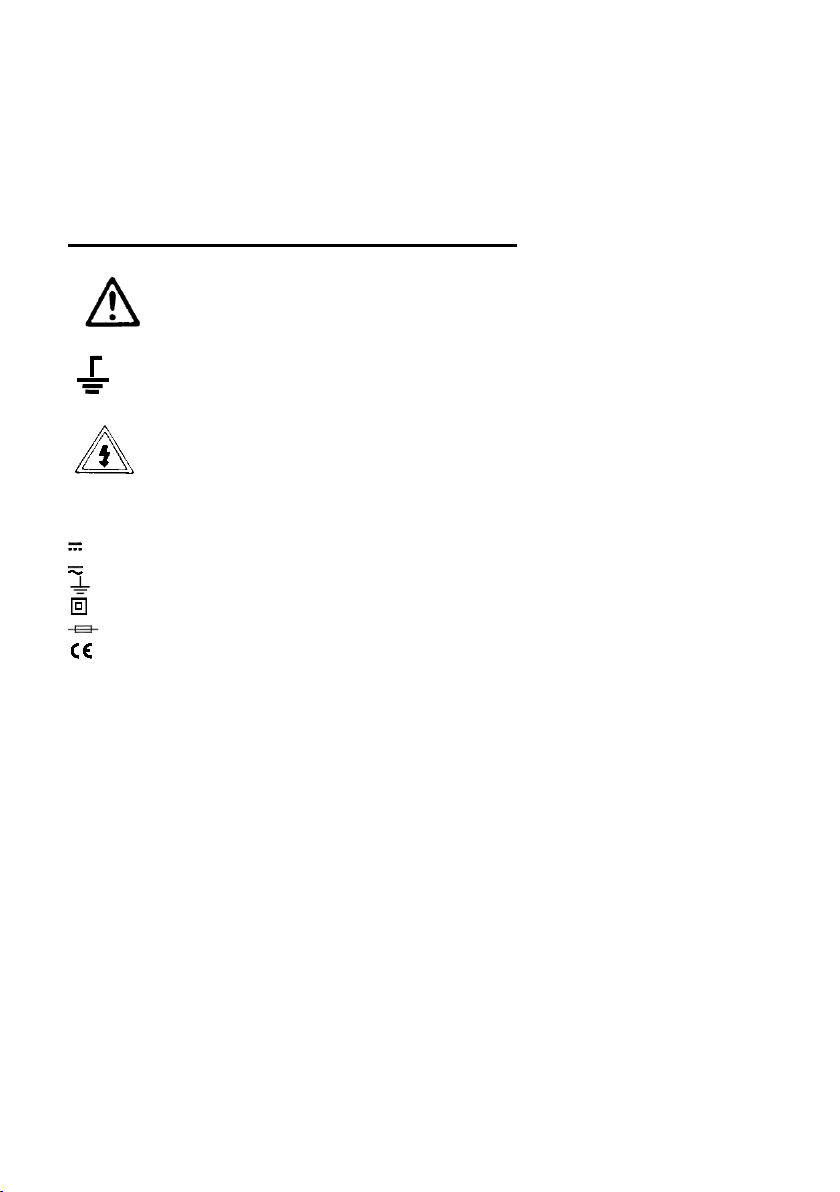
Reinigung des Gerätes:
~
Wechselspannung/-strom (AC)
Gleichspannung/-strom (DC)
AC oder DC
Erde
Doppelt isoliert
Sicherung
Entspricht den Richtlinien der europäischen Union
MAX
1000V
Gerät nur mit einem feuchten, fusselfreien Tuch reinigen. Nur handelsübliche Spülmittel
verwenden.
Beim Reinigen unbedingt darauf achten, dass keine Flüssigkeit in das Innere des
Gerätes gelangt. Dies könnte zu einem Kurzschluss und zur Zerstörung des Gerätes
führen.
1.2 Sicherheitssymbole und Hinweise am Gerät
Achtung! Entsprechende(n) Abschnitt(e) in der Bedienungsanleitung
nachlesen. Nichtbeachtung birgt Verletzungsgefahr und/oder die Gefahr der
Beschädigung des Gerätes.
Max. zulässige Potentialdifferenz von 1000 V DC/AC
bzw. Ohm-Eingang und Erde aus Sicherheitsgründen nicht überschreiten.
Gefährlich hohe Spannung zwischen den Eingängen.
Extreme Vorsicht bei der Messung. Eingänge und Messspitzen nicht
berühren. Sicherheitshinweise in der Bedienungsanleitung beachten!
zwischen COM-/ V-/
eff
Achtung!
Mögliche Gefahrenquelle. Sicherheitsvorschriften unbedingt beachten. Bei
Nichtbeachtung besteht u. U. Verletzungs- oder Lebensgefahr und/oder die Gefahr der
Beschädigung des Gerätes.
-5-
Page 6

2. Einführung
Professionelles True RMS Grafikmultimeter mit eingebauter Wärmebildkamera und
TFT-Farbdisplay, schnellem A/D-Wandler und hoher Messgenauigkeit. Einfache
Fehlersuche im industriellen und privaten Einsatz dank Bluetooth-Schnittstelle und
robustem IP65-Gehäuse.
Hauptmerkmale
• 6000 Counts 2.8'' TFT-Farbanzeige
• Wärmebildkamera mit 50 Hz Bildwiederholrate
• DC Spannung, AC, AC+DC TRMS Spannung
• DC Strom, AC, AC+DC TRMS Strom
• Widerstandsmessung und Durchgangsprüfung
• Diodentest
• Kapazitätsmessung
• Frequenz, Tastverhältnis
• Temperatur über Typ-K-Messfühler
• Strommessungen mit optionalem Stromwandler
• PC-Software zur Wärmebildanalyse
• Bluetooth 4.0 Schnittstelle
• Android & iOS App als Download
-6-
Page 7
3. Beschreibung
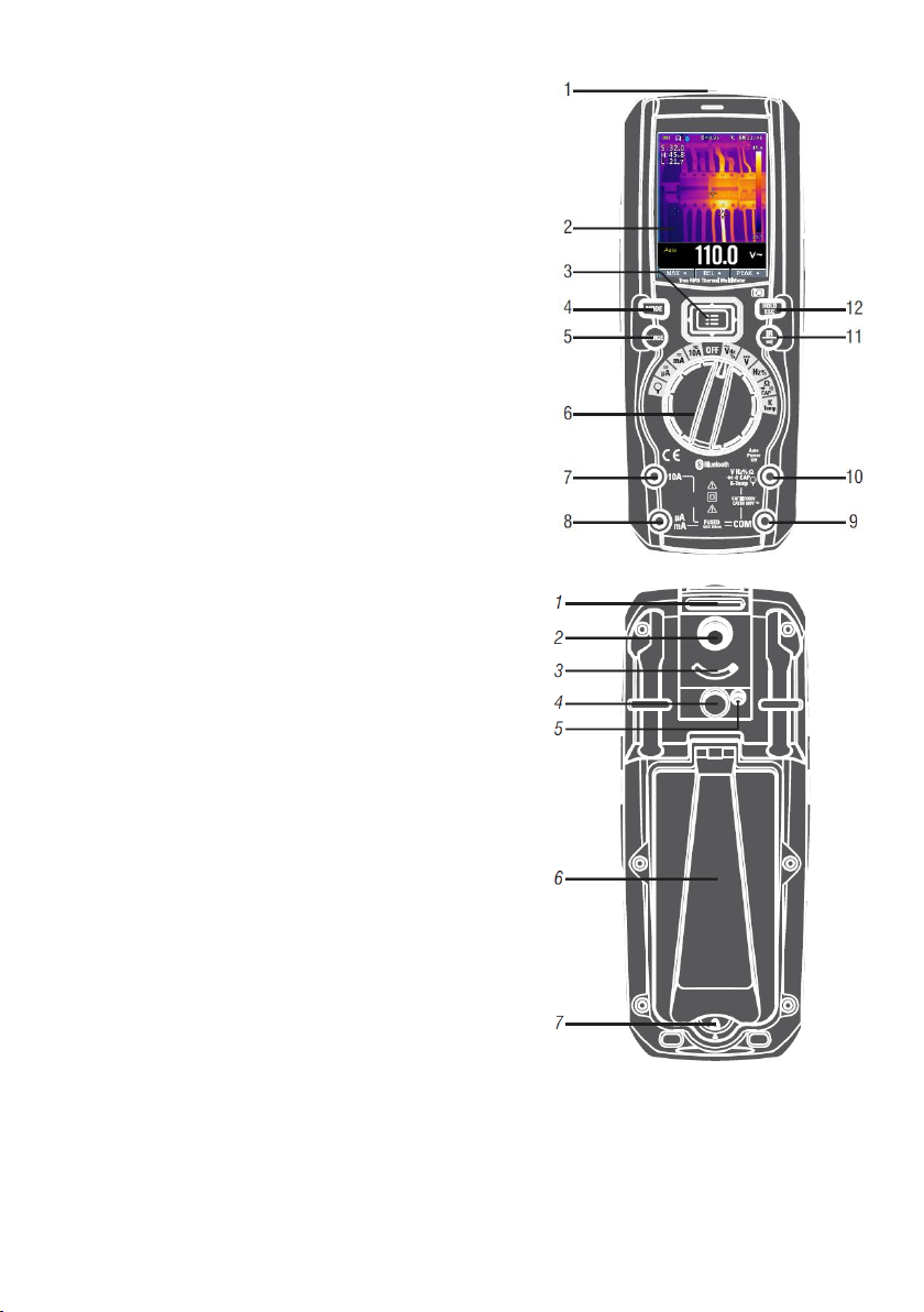
3.1. Vorder- und Rückseite
1. NCV (Berührungsloser Spannungsprüfer)
2. TFT-Farbanzeige
3. Navigations-/Menü-Tasten
4. MODE-Taste
5. RANGE-Taste (man. Bereichsumschaltung)
6. Wahlschalter
7. Positive (+) Buchse A (Strom).
8. Positive (+) Buchse mA (Strom).
9. COM(-) Buchse
10. Positive(+) Buchse für alle Messmodi außer
A und mA
11. Wärmebildmodus/Taschenlampe
12. Hold/Capture (Messwert anhalten/speichern)
1. Öffnung für Magnethalterung
2. Wärmebildkameralinse
3. Linsenabdeckung
4. Taschenlampe
5. Laser
6. Standfuß
7. Batteriefachverschluss
-7-
Page 8
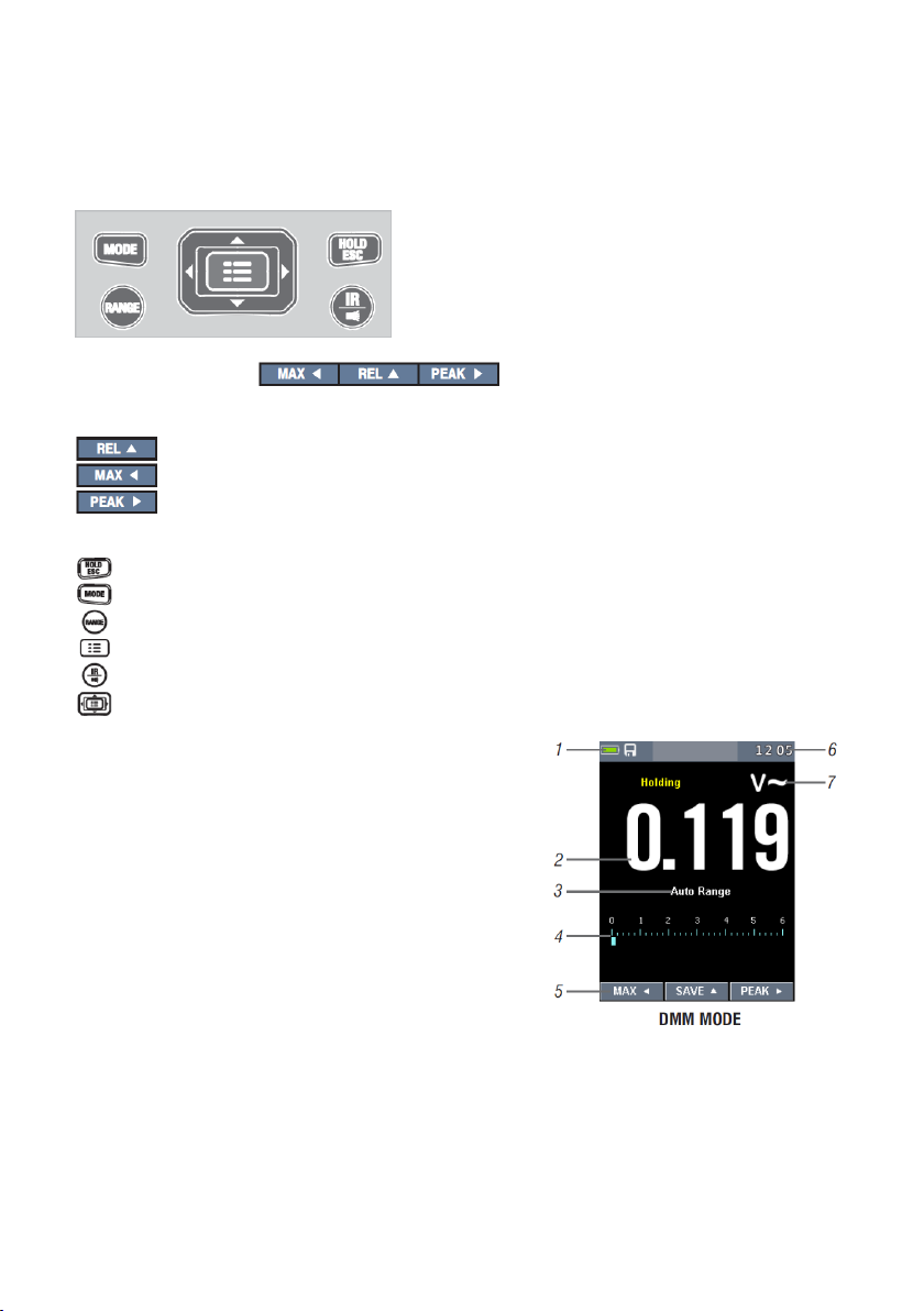
3.2. Beschreibung des Tastenfelds
Die 9 Tasten erweitern die Funktionalität der Multimeter-Hauptfunktionen, die mit dem
Wahlschalter ausgewählt werden. Die Tasten sind in Navigations- und Funktionstasten
unterteilt.
Navigationstasten:
Navigation durch das Menü, Auswählen eines Menüpunktes und Werteingabe
Taste “nach oben”, um Relativwertanzeige zu aktivieren
Taste “nach links”, um Max-/Min-Wertanzeige zu aktivieren
Taste “nach rechts”, um Spitzenwertanzeige zu aktivieren
Funktionstasten:
HOLD hält den aktuellen Wert und erlaubt eine Speicherung. Außerdem
reaktiviert sich das Gerät nach automatischer Abschaltung mit dieser Taste
Mit MODE wird zwischen einzelnen Modi umgeschaltet
RANGE: Manuelle Bereichswahl.
Menü-Taste.
IR-Taste aktiviert die Modi DMM MODE und IR+DMM MODE.
Navigationstasten.
3.3. Anzeige
DMM MODE und IR+DMM MODE
1. Akkuladeanzeige
2. Messwert
3. Automatische/Manuelle Bereichswahl
4. Bargraph
5. Funktion der Navigationstasten
6. Systemzeit
7. Einheit der Messung
-8-
Page 9
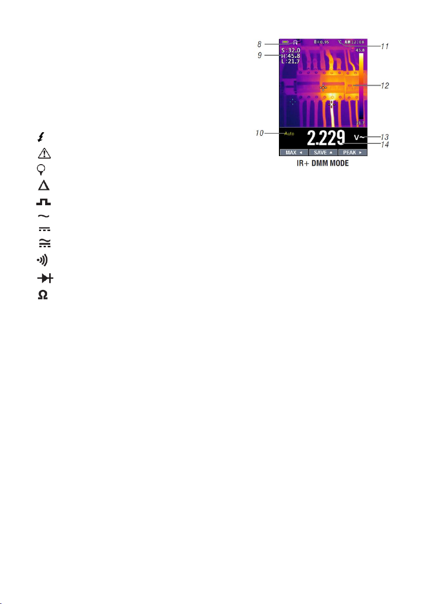
8. SD-Karte
9. Temperaturmesswerte
10. Automatische/Manuelle Bereichswahl
11. Temperatureinheit
12. Wärmebildkamera
13. Einheit der Messung
14. Messwert
Symbole:
Spannung größer 30V (AC oder DC)
Warnung
Flexibler Stromwandler
(Delta) Relative Messung
Tastverhältnis
AC Spannung/Strom
DC Spannung/Strom
AC+DC Spannung/Strom
Durchgangsprüffunktion
Diodenmessfunktion
Widerstandsmessfunktion
-9-
Page 10
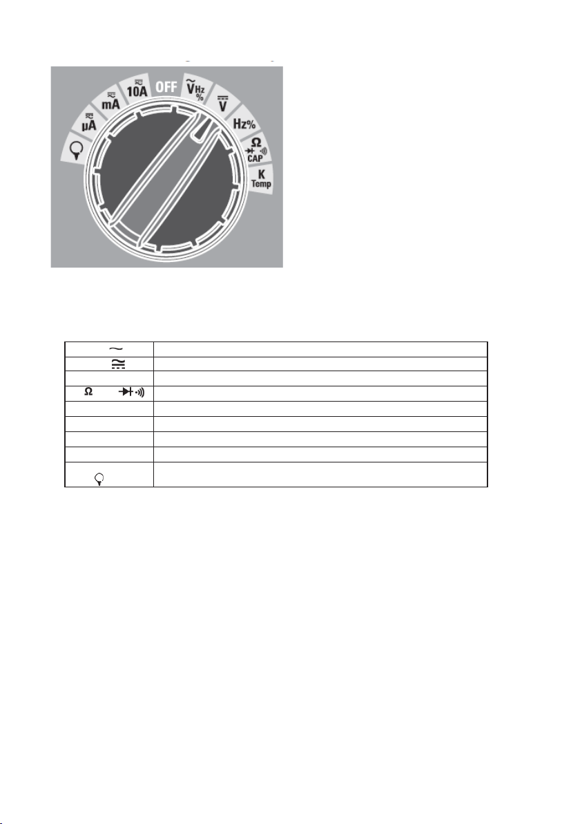
3.4 Bereichswahlschalter
V
AC Spannung
V
DC und AC+DC Spannung
HZ %
Frequenz und Tastverhältnis
CAP
Widerstand, Diode, Kapazität und Durchgang
K Temp
Temperatur
A
AC, DC und AC+DC Strom
mA
AC, DC und AC+DC Milliampere-Strom
µA
AC, DC and AC+DC Mikroampere-Strom bis zu 6,000 μA
Stromwandler
Wählen Sie den gewünschten Messbereich, indem Sie den Bereichswahlschalter in die
jeweilige Stellung bewegen. Zu jeder Funktion gibt es eine Standard-Anzeige (Bereich,
Einheit und Unterfunktionen). Getätigte Einstellungen in einem Bereich übertragen sich
nicht automatisch auf einen anderen Messbereich.
-10-
Page 11
4. DMM: Messung und Einstellungen
4.1 DC-Spannung
WARNUNG: Keine Messungen beim Ein- oder Ausschalten
eines Motors vornehmen. Evtl. entstehende Spannungsspitzen
können das Gerät beschädigen.
- Bereichswahlschalter auf VDC stellen
- Schwarze Messleitung an COM anschließen
- Rote Messleitung an V anschließen
- Messwert ablesen
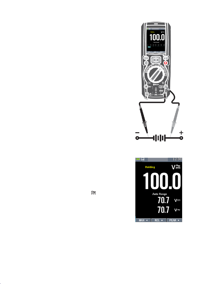
4.2 AC+DC-Spannung
WARNUNG: Keine Messungen beim Ein- oder Ausschalten
eines Motors vornehmen. Evtl. entstehende
Spannungsspitzen können das Gerät beschädigen.
- Bereichswahlschalter auf VDC stellen
- Schwarze Messleitung an COM anschließen
- Rote Messleitung an V anschließen
- MODE-Taste einmal drücken
- Messwert ablesen
-11-
Page 12
4.3 AC-Spannung
WARNUNG: Stromschlaggefahr. Messspitzen können zu
kurz sein, um die Kontakte der Steckdose zu erreichen.
Dies kann fälschlicherweise als ein spannungsloser
Stromkreis interpretiert warden. Stellen Sie daher immer
sicher, dass ein Kontakt zu leitenden Teilen besteht.
WARNUNG: Keine Messungen beim Ein- oder Ausschalten
eines Motors vornehmen. Evtl. entstehende
Spannungsspitzen können das Gerät beschädigen.
- Bereichswahlschalter auf VAC stellen
- Schwarze Messleitung an COM anschließen
- Rote Messleitung an V anschließen
- Messwert ablesen
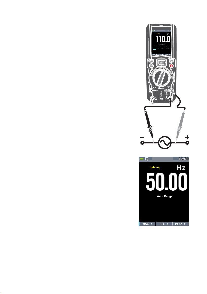
4.4 Frequenz
- Bereichswahlschalter auf Hz % stellen.
- Schwarze Messleitung an COM anschließen
- Rote Messleitung an V anschließen
- Messwert ablesen
- MODE-Taste aktiviert den Tastverhältnis-Modus.
- Tasverhältnis-Messwert ablesen
-12-
Page 13
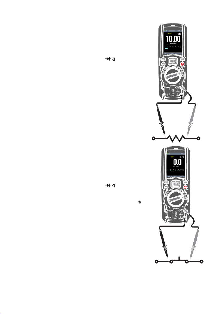
4.5 Widerstand
WARNUNG: Um Stromschläge zu vermeiden, Prüfling vor
der Messung ausschalten und alle darin befindlichen
Kondensatoren entladen. Evtl. vorhandene Batterien
herausnehmen und Netzstecker ziehen.
- Bereichswahlschalter auf Ω CAP stellen.
- Schwarze Messleitung an COM anschließen
- Rote Messleitung an Ω anschließen
- Widerstandsmesswert ablesen
4.6 Durchgangsprüfung
WARNUNG: Um Stromschläge zu vermeiden, Prüfling vor
der Messung ausschalten und alle darin befindlichen
Kondensatoren entladen. Evtl. vorhandene Batterien
herausnehmen und Netzstecker ziehen.
- Bereichswahlschalter auf Ω CAP stellen.
- Schwarze Messleitung an COM anschließen
- Rote Messleitung an V anschließen
- MODE-Taste aktiviert den Durchgangs-Modus ( )
- Ist der Widerstandswert geringer als 50Ω, ertönt
kein Signal. Bei unterbrochenem Stromkreis bzw. zu
hohem Widerstandswert erscheint „OL“
(Messbereichsüberschreitung)
-13-
Page 14
4.7 Diode
WARNUNG: Um Stromschläge zu vermeiden, Prüfling vor
der Messung ausschalten und alle darin befindlichen
Kondensatoren entladen. Evtl. vorhandene Batterien
herausnehmen und Netzstecker ziehen.
- Bereichswahlschalter auf Ω CAP stellen.
- Schwarze Messleitung an COM anschließen
- Rote Messleitung an V anschließen
- MODE-Taste aktiviert den Dioden-Modus ( )
- In Flussrichtung einer Diode fallen je nach Typ 0,4
V bis 3,0 V ab. In Sperrrichtung und bei offenem
Stromkreis erscheint „OL“. Kurzgeschlossene
Halbleiter haben einen Wert nahe 0 V in beiden
Richtungen.
4.8 Kapazität
WARNUNG: Um Stromschläge zu vermeiden, Prüfling vor
der Messung ausschalten und alle darin befindlichen
Kondensatoren entladen. Evtl. vorhandene Batterien
herausnehmen und Netzstecker ziehen.
- Bereichswahlschalter auf Ω CAP stellen.
- Schwarze Messleitung an COM anschließen
- Rote Messleitung an V anschließen
- MODE-Taste aktiviert den Kapazitäts-Modus (CAP)
- Kapazitäts-Messwert ablesen
-14-
Page 15
4.9 Temperatur
- Bereichswahlschalter auf TEMP (°C oder °F)
setzen.
- Temperaturmessfühler und Adapter gem.
Polarität (+ an V, - an COM) anschließen
- Temperaturmesswert ablesen
- Taste MODE schaltet zwischen den
Einheiten (°C/°F).
4.10. Strommessungen mit Stromwandler (AC)
- Bereichswahlschalter auf setzen
- Schwarze (bzw. negative) Messleitung an COM anschließen
- Rote (bzw. positive) Messleitung an V anschließen
- Strommesswert ablesen
- Taste RANGE passt den Messbereich an:
(30 A bei 100 mV/A, 300 A bei 10 mV/A, 3.000 A bei 1 mV/A)
-15-
Page 16
4.11. DC-Strom
- Schwarze Messleitung an COM anschließen
- Für Ströme bis 6000μA DC Bereichswahlschalter
auf µA setzen und rote Messleitung an µA/mA
anschließen
- Für Ströme bis 600mA DC Bereichswahlschalter
auf mA setzen und rote Messleitung an µA/mA
anschließen
- Für Ströme bis 10A DC Bereichswahlschalter auf
10A setzen und rote Messleitung an 10A
anschließen
- Strommesswert ablesen
4.12. AC-Strom
WARNUNG: Keine Strommessungen von Strömen über 10
A länger als 30 Sekunden vornehmen. Die Messleitungen
oder das Gerät können sonst beschädigt warden.
- Schwarze Messleitung an COM anschließen
- Für Ströme bis 6000μA AC Bereichswahlschalter
auf µA setzen und rote Messleitung an µA/mA
anschließen
- Für Ströme bis 600mA AC Bereichswahlschalter auf
mA setzen und rote Messleitung an µA/mA
anschließen
- Für Ströme bis 10A AC Bereichswahlschalter auf
10A setzen und rote Messleitung an 10A
anschließen
- Taste MODE drücken, bis “ ” angezeigt wird
- Strommesswert ablesen
-16-
Page 17
4.13 AC+DC-Strom
WARNUNG: Keine Strommessungen von Strömen über 10 A
länger als 30 Sekunden vornehmen. Die Messleitungen oder
das Gerät können sonst beschädigt warden.
- Schwarze Messleitung an COM anschließen
- Für Ströme bis 6000μA AC+DC
Bereichswahlschalter auf µA setzen und rote
Messleitung an µA/mA anschließen
- Für Ströme bis 600mA AC+DC
Bereichswahlschalter auf mA setzen und rote
Messleitung an µA/mA anschließen
- Für Ströme bis 10A AC+DC Bereichswahlschalter
auf 10A setzen und rote Messleitung an 10A
anschließen
- Taste MODE drücken, bis “ ” angezeigt wird
- Strommesswert ablesen
4.14 Taste RANGE
RANGE aktiviert die manuelle Bereichswahl und “Manual
Range” erscheint außerdem auf der Anzeige. Erneutes Drücken der Taste RANGE stellt
den nächstgrößten Messbereich ein und das Komma wird entsprechend nach rechts
verschoben. Folgende Bereiche unterstützen keine RANGE-Taste:
% Temp 10A
Halten Sie die RANGE-Taste für länger als eine Sek.
Gedrückt, um zurück in den automatischen Modus zu
wechseln.
-17-
Page 18
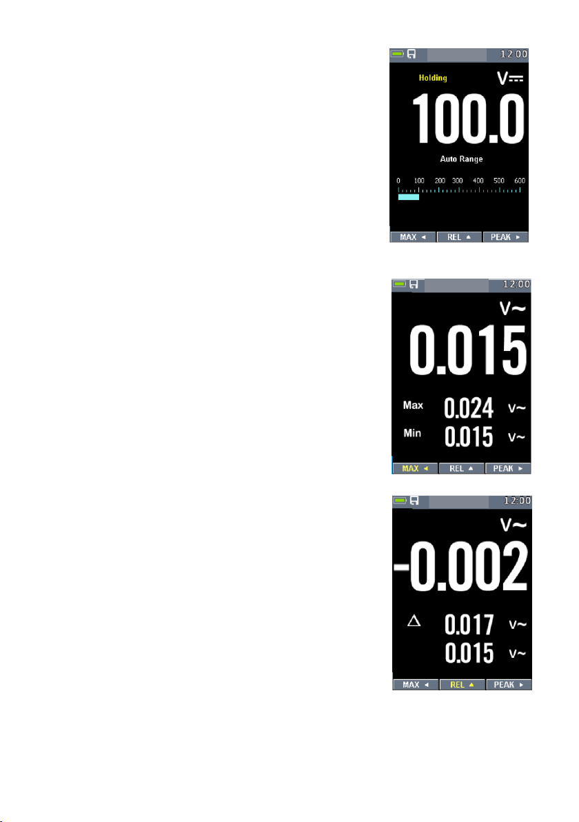
4.15 Taste Hold
Taste HOLD friert den aktuell angezeigten Wert der
Anzeige ein. So ist es möglich, sich den sich sonst
ändernden Messwert nach der Messung zu notieren.
4.16 Minimum und Maximum
Im Modus MAX/MIN werden die jeweils höchsten und
niedrigsten Messwerte gespeichert. Ist der aktuelle
Messwert z.B. größer als der bisher vorhandene MAX-Wert,
so wird der MAX-Wert gleich dem aktuellen Messwert
gesetzt. Sie aktivieren den MAX/MIN-Modus, indem Sie die
Taste ◄ drücken. Erneutes Drücken der Taste schließt den
MAX/MIN-Modus.
4.17 Relative Messungen
Um den relativen Modus zu aktivieren, drücken Sie auf ▲.
Dieser Modus versetzt den Nullpunkt entsprechend dem
aktuellen Messwert.
Erneutes Drücken der Taste deaktiviert diesen Modus.
-18-
Page 19
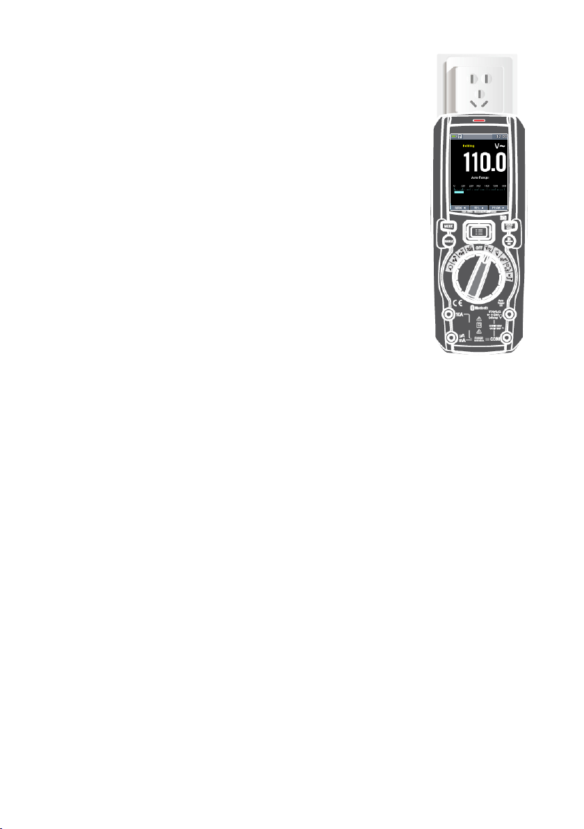
4.19 (NCV) Berührungslose Spannungsprüfung
(100 bis 1000 VAC)
WARNUNG: Um Stromschläge zu vermeiden, die
Spannungsprüfung immer zuerst an einem unter Strom
stehenden Leiter testen. Isolationsart, Abstand und
Abschirmung wirken sich auf die Prüfung aus. Bei
Unsicherheiten ist die direkte Spannungsmessung vorzuziehen.
- Der NCV-Prüfer funktioniert in jedem beliebigen
Messbereich und ist im OFF-Zustand des Geräts
deaktiviert
- Nähern Sie sich einer stromführenden Leitung wie
abgebildet
- Ist eine AC-Spannung vorhanden, leuchtet die rote
LED über der Anzeige
HINWEIS: Der NCV-Prüfer besitzt eine entsprechend hohe
Empfindlichkeit gegenüber elektrostatischen Feldern. So ist ein
Auslösen der roten LED unter Umständen möglich, auch wenn
keine Wechselstromleitung in der Nähe ist.
-19-
Page 20
5 Wärmebildkamera und Digitalmultimeter (DMM)
5.1 Wärmebildkamera
Im Wärmebild- und DMM-Modus ist gleichzeitiges Arbeiten mit der Kamera und Messen
mit dem Multimeter möglich. Die DMM-Anzeige befindet sich unter dem Bild der
Kamera.
- Drücken Sie die Taste IR, um die Wärmebildkamera zu aktivieren.
- Öffnen Sie die Schutzabdeckung der Linse
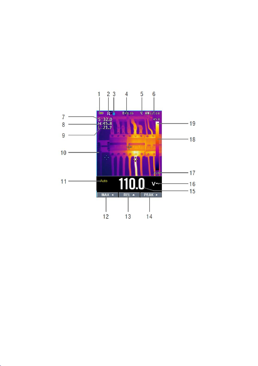
1. Batteriezustandsanzeige
2. SD-Karten-Symbol, falls eine SD-Karte eingesteckt ist.
3. Bluetooth-Symbol, falls es aktiviert ist.
4. Ausgewählter Emissionsgrad. In den Einstellungen kann dieser Wert verändert
werden.
5. Temperatureinheit, In den Einstellungen lässt sich die Einheit zwischen °C,℉,K
wählen.
6. Systemzeit
7. Temperatur im Mittelpunkt
8. H: der wärmste Punkt im Bild
9. C: der kälteste Punkt im Bild
10. Bild der Wärmebildkamera
11. Bereichswahl-Modus
12. MAX
13. REL
14. PEAK
-20-
Page 21

15. DMM-Anzeige
16. Einheit der DMM-Anzeige
17. Geringster Wert des aktuellen Frames
18. Die Skala gibt ein Farbspektrum zwischen dem Wert (17.) und (19.) vor, wonach
sich die einzelnen Temperaturpunkte richten. Hellere Farben entsprechen somit einer
höheren Temperatur und umgekehrt dunklere Farben einer niedrigeren Temperatur.
19. Höchster Punkt des aktuellen Frames
5.2 Benutzung der Wärmebildkamera
1.Bereichswahlschalter auf beliebige Position stellen.
2.Taste “IR” drücken, um die Kamera zu aktivieren. Richten Sie die Linse auf das
Messobjekt.
3.In der linksoberen Ecke werden die Temperaturmesswerte angezeigt, oben in der
Mitte der Emissionsgrad
4.In den Einstellungen kann zusätzlich der Laser aktiviert werden
5.Unter “Messung” in den Einstellungen können Sie den Max/Min-Wert (de)aktivieren
6.Die Multimeterfunktionen bleiben von der Wärmebildkamera unberührt
7.HOLD-Taste friert das Wärmebild ein, welches später mit Taste ▲(SAVE) auf der SDKarte gespeichert werden kann. Drücken Sie nochmals HOLD, falls keine Speicherung
gewünscht ist.
8.Das Sichtfeld FOV (Field of View) beträgt 21 x 21 Grad.
9.FOV bestimmt die maximale Fläche, die mit der Linse erfasst werden kann.
10.Nachfolgende Tabelle enthält weitere Einzelheiten der eingesetzten Linse:
-21-
Page 22
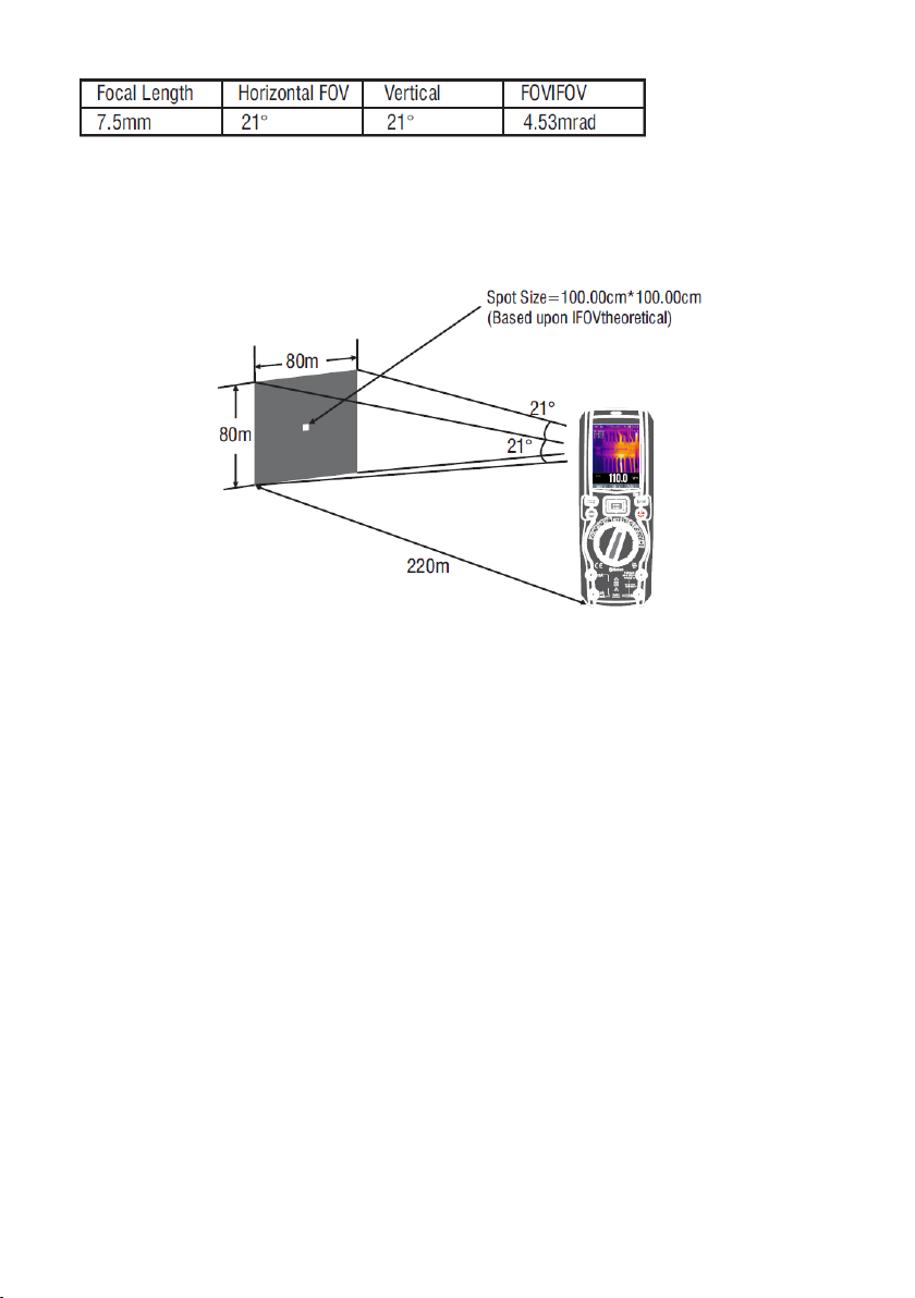
IFOV (Instantaneous Field of View) ist das kleinste Detail innerhalb des FOV, was
detektiert werden kann. Die Einheit ist rad.
IFOV = (Pixelgröße) / (Brennweite d. Linse);
D:S
theoretical
(= 1/ IFOV
) ist die berechnete Punktgröße.
theoretical
Horizontales FOV ist 21°, Vertikales FOV ist 21°, IFOV ist 34um/7.5mm = 4.53mrad;
D:S
theoretical
(= 1/ IFOV
theoretical
) = 220:1
D:S
ist. Gewöhnlich ist D:S
measure
(= 1/ IFOV
) ist die Punktgröße, die zur genauen Messung erforderlich
measure
um 2-3 mal größer als D:S
measure
theoretical
. D.h., dass die
praktische Fläche 2-3 mal größer sein sollte als der theoretisch errechnete Wert.
-22-
Page 23
5.3 Benutzung des Multimeters und Wärmekamera
Im IR+DMM-Modus können die Tasten MODE, RANGE, HOLD und REL wie gewohnt
verwenden werden.
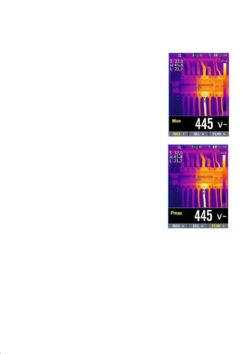
MAX/MIN im IR+DMM-Modus
1. Um den MAX/MIN-Modus zu aktivieren, Taste ◄
drücken, es erscheint Max.
2. Drücken Sie die Taste ◄ erneut, um den Min-Modus zu
wählen. Ein erneutes Drücken oder längeres
Gedrückthalten der Taste beendet den MAX/MIN-Modus
PEAK-Werte in IR+DMM-Modus
1. Um den PEAK-Modus bei ACV oder ACA zu aktivieren,
Taste ► drücken
2. Ein erneutes Drücken oder längeres Gedrückthalten der
Taste beendet den PEAK-Modus
-23-
Page 24

6 Einstellungen
6.1 Benutzung des Menüs
Drücken Sie die Menü-Taste:
Drücken Sie die Tasten mit den Pfeilen nach oben und nach unten, um durch die
Menüpunkte zu gehen. Taste mit dem Pfeil nach rechts oder Menütaste wählen den
Punkt aus bzw. gehen in die nächste Menüebene. Taste mit dem Pfeil nach links
schließt das Menü bzw. macht die Auswahl rückgängig. Die Tasten
MODE/RANGE/HOLD/IR schließen das Menü aus jedem Unterpunkt heraus.
6.2 Untermenüs
Palette
Es gibt insgesamt 5 Farbpaletten:
Wählen Sie mit der Taste Pfeil nach rechts oder Menütaste die gewünschte Farbpalette
aus.
6.3 Temperatureinheit
Wählen Sie mit der Taste Pfeil nach rechts oder Menütaste die Einstellung der
Temperatureinheit aus, das Symbol erscheint daraufhin in schwarz . Drücken Sie
die Taste Pfeil nach rechts oder Menütaste, um zwischen den Optionen °C, °F, K zu
wechseln. Mit der Taste Pfeil nach links wechseln Sie wieder ins Menü.
-24-
Page 25

6.4 Messung
Wählen Sie mit der Taste Pfeil nach rechts oder Menütaste
die Einstellung “Messung” aus. Zwei Einstellungen können
aktiviert/deaktiviert werden: Temp. Max und Temp. Min.
Navigieren Sie zu einem dieser Punkte mit den Tasten nach
oben/unten und wählen Sie dann den Punkt mit der Taste
nach rechts oder Menütaste aus.
Temp. Max: Anzeige der automatisch ermittelten höchsten
Temperatur des Frames.
Temp. Min: Anzeige der automatisch ermittelten niedrigsten
Temperatur des Frames.
6.5 Emissivität
Wählen Sie mit der Taste Pfeil nach rechts oder Menütaste die Einstellung “Emissivität”
aus. Nun kann der Wert im Bereich von 0,01 und 0,99 eingestellt werden. Wechseln Sie
zum Menü mit der Taste nach links.
6.6 Sprache
Wählen Sie mit der Taste Pfeil nach rechts oder Menütaste
die Einstellung “Sprache” aus. Sie können dann eine
Sprache aus der Liste mit den Tasten Pfeile nach
oben/unten auswählen.
Derzeit verfügbar: Deutsch, Englisch, Französisch,
Portugiesisch, Spanisch, Italienisch, Chinesisch (tradit.,
vereinfacht)
6.7 Einstellung
Wählen Sie mit der Taste Pfeil nach rechts oder Menütaste die Einstellung “Einstellung”
aus.
Fünf Einstellungen sind möglich: Tastenton, Bluetooth, Laser, Helligkeit and Auto Power
Off (autom. Abschaltung des Geräts).
-25-
Page 26

6.8 Bluetooth-Schnittstelle
1. Aktivieren Sie die Bluetooth-Schnittstelle des Geräts.
2. Aktivieren Sie Bluetooth an Ihrem
Smartphone, installieren und starten
Sie Thermview+.
3. Wählen Sie dann das P 3450 aus der
Liste der Bluetooth-Geräte aus, die
Verbindung wird hergestellt.
Für eine detailierte Beschreibung der APP
Thermview+, bitte Help im APP-Menü
auswählen.
Thermview+ für Android:
Im Google Play nach
“Thermview+ suchen.
Thermview+ für iOS:
Im Apple Store nach
“Thermview+”suchen.
-26-
Page 27

6.9 Datum/Zeit
Wählen Sie mit der Taste Pfeil nach rechts oder Menütaste
die Einstellung “Datum/Zeit”. Hier kann die Systemzeit und
Datum eingestellt werden. Die Änderungen werden nach
dem Verlassen des Menüpunkts aktiv.
6.10 Speicher
Wählen Sie mit der Taste Pfeil nach rechts oder Menütaste
die Einstellung “Speicher”. Zwei Optionen stehen zur
Auswahl: Bilder abrufen, Bilder löschen.
Bilder abrufen: Wählen Sie mit der Taste Pfeil nach rechts
oder Menütaste die Einstellung Bilder abrufen, das Menü
wird damit geschlossen und Sie befinden sich im
Bildervorschau-Modus.
Bilder löschen: Wählen Sie mit der Taste Pfeil nach rechts
oder Menütaste die Einstellung Bilder löschen. Sie werden
dann gefragt, ob alle Fotos gelöscht werden sollen.
-27-
Page 28

6.11 Information
Wählen Sie mit der Taste Pfeil nach rechts oder Menütaste
die Einstellung „Information“. Dieser Punkt enthält die
Version der Soft- und Hardware des Geräts.
6.12 Reset Param. (Zurücksetzung auf
Auslieferungszustand)
Hiermit können Sie sämtliche Einsetellungen des Geräts
zurücksetzen.
-28-
Page 29

6.13 Aufzeichnung (Datalogger-Funktion)
Im Punkt “Aufzeichnung” können Sie eine zeitliche Aufzeichnug der Messwerte
konfigurieren und durchführen. Wählen sie hierzu Aufzeichnung starten.
Im Unterpunkt Speicher können Sie mit Pfeiltasten die aufgenommenen Messwerte
aufrufen.
Die Punkte Messintervall und Dauer legen die zeitlichen Komponenten fest.
(Fig133) Messintervall von 1s bis 59min:59s.
(Fig134) Dauer von 1min bis 9h:59min.
-29-
Page 30

Wählen Sie den Punkt Aufzeichnung starten aus. Am Ende
der Messung oder falls Sie eher STOP drücken (Taste Pfeil
nach rechts) können Sie die Aufzeichnung speichern (Taste
Pfeil nach oben “SAVE”).
Wählen Sie den Punkt Speicher aus. Hier können Sie Ihre
einzelnen Aufzeichnungen auswählen und die
Trendanzeige aktivieren.
Die Trendanzeige erlaubt es dem Benutzer, sich den
zeitlichen Verlauf der Messung zu betrachten.
-30-
Page 31

Benutzen Sie die Taste Pfeil nach oben, um zu zoomen und
die Tasten Pfeil nach links/rechts, um zu scrollen.
Sie können unter “Alle Aufzeich. Löschen” alle
Aufzeichnungen löschen.
-31-
Page 32

7 Bilderspeicher (Wärmebildkamera/DMM)
Unter dem Menüpunkt Speicher können
gespeicherte Bilder (SD-Karte ) aufgerufen und
gelöscht werden.
1.nach links blättern (ältere Bilder)
2.Dateiname
3. nach rechts blättern (neuere Bilder)
4.gespeicherte Anzeige
Aktuelle Anzeige speichern
Im Messmodus (Wärmebildkamera+DMM oder
nur DMM-Modus) Taste HOLD drücken. Im
nächsten Punkt Taste nach oben drücken
(Auswahl SAVE).
-32-
Page 33

8 Technische Spezifikationen
Field of view (FOV) /
21° x 21°/ 0.5m
Räumliche Auflösung (IFOV)
4.53mrad
IR-Auflösung
80 × 80 pixels
Therm. Empfindlichkeit/NETD
<
0.1°C @ +30°C (+86°F) / 100 mK
Wiederholrate
50Hz
Fokusmodus
ohne
Brennweite
7.5mm
Focal Plane Array (FPA)/Spektralbereich
Uncooled microbolometer / 8–14 µm
Objekt-Temperaturbereich
–20°C to +260°C (–4°F to +500°F)
Genauigkeit
±3°C (±5.4°F) or ±3% of reading (Environment temperature
10℃-35°C, object temperature >0°C. )
Bereich
Auflösung Genauigkeit
Eingangsimpedanz
Überspannungsschutz
600.0mV
0.1mV
±(0.09%reading + 5digits)
>10MΩ
1000VDC/ACrms
6.000V
0.001V
60.00V
0.01V
600.0V
0.1V
±(0.2%reading + 5digits)
1000V
1V
Bereich
Auflösung
Genauigkeit
(*)
Überspannungsschutz
(50Hz÷60Hz)
(61Hz÷1kHz)
6.000V
0.001V
±(0.8%reading+5digi
ts)
±(2.4%reading+5dgt)
1000VDC/ACrms
60.00V
0.01V 600.0V
0.1V 1000V
1V
Bereich
Auflösung
Genauigkeit
(50Hz÷1kHz)
Eingangsimpedanz
Überspannungsschutz
6.000V
0.001V
±(2.4%reading +20dgt)
>10MΩ
1000VDC/ACrms
60.00V
0.01V
600.0V
0.1V
1000V
1V
8.1 Wärmebildkamera
Genauigkeit berechnet als [%reading + (num. digits*Auflösung)] bei 18°C ÷ 28°C
<75%RH
DC Spannung
AC TRMS Spannung
(*) Genauigkeit spezifiziert von 10% bis 100% des Messbereichs,
Sinus,
Eingangsimpedanz: >9MΩ;
Genauigkeit PEAK: ±10%rdg, PEAK Ansprechzeit: 1ms
AC+ DC TRMS Spannung
-33-
Page 34

DC Strom
Bereich
Auflösung
Genauigkeit
Überspannungsschutz
600.0uA
0.1uA
±(0.9%reading + 5digits)
Quick fuse 800mA/1000V
6000uA
1uA 60.00mA
0.01mA
600.0mA
0.1mA ±(0.9%reading + 8digits)
10.00A
0.01A ±(1.5%reading + 8digits)
Quick fuse 10A/1000V
Bereich
Auflösung
Genauigkeit(*)(50Hz÷1kHz)
Überspannungsschutz
600.0uA
0.1uA
±(1.2%reading + 5digits)
Quick fuse 800mA/1000V
6000uA
1uA
60.00mA
0.01mA
600.0mA
0.1mA
10.00A
0.01A ±(1.5%reading + 5digits)
Quick fuse 10A/1000V
Bereich
Auflösung
(50Hz÷60Hz)
(61Hz÷1kHz)
Überspannungsschutz
30.00A
0.01A
±(0.8%reading+5digi
ts)
±(2.4%reading+5dgt)
1000VDC/ACrms
300.0A
0.1A
3000A
1A
Funktion Teststrom
Leerlaufspannung
<1.5mA
3.3VDC
Bereich
Auflösung
Genauigkeit
Ton Überspannungsschutz
600.0Ω
0.1Ω
±(0.5%reading + 10dgt)
<50Ω
1000VDC/ACrms
6.000kΩ
0.001kΩ
±(0.5%reading + 5digits)
60.00kΩ
0.01kΩ
600.0kΩ
0.1kΩ
6.000MΩ
0.001MΩ
60.00MΩ
0.01MΩ
±(2.5%reading + 10dgt)
AC TRMS Strom
(*) Genauigkeit spezifiziert von 5% bis 100% des Messbereichs, Sinus.
Genauigkeit PEAK-Funktion: ±10%rdg , AC+DC TRMS Strom: Genauigkeit (50Hz÷1kHz):
±(3.0%reading + 20dgt)
Stromwandler
Diodentest
Widerstand und Durchgangsprüfung
-34-
Page 35

Frequenz (Sinus)
Bereich
Auflösung
Genauigkeit
Überspannungsschutz
40.00Hz÷10kHz
0.01Hz÷0.001kHz
±(0.5%reading)
1000VDC/ACrms
Bereich
Auflösung
Genauig-keit
Überspannungsschutz
60.00Hz
0.01Hz
±(0.09%rdg+5digits)
1000VDC/ACrms
600.0Hz
0.1Hz
6.000kHz
0.001kHz
60.00kHz
0.01kHz
600.0kHz
0.1kHz
6.000MHz
0.001MHz
10.00MHz
0.01MHz
Bereich
Auflösung
Genauigkeit
5.0%÷95.0%
0.1%
±(1.2%reading + 2digits)
Bereich
Auflösung
Genauigkeit
Überspannungsschutz
60.00nF
0.01nF
±(1.5%reading + 20dgt)
1000VDC/ACrms
600.0nF
0.1nF
±(1.2%reading + 8digits)
6.000uF
0.001uF
±(1.5%reading + 8digits)
60.00uF
0.01uF
±(1.2%reading + 8digits)
600.0uF
0.1uF
±(1.5%reading + 8digits)
6000uF
1uF
±(2.5%reading + 20dgt)
Bereich
Auflösung Genauigkeit (*)
Überspannungsschutz
-40.0°C ÷ 600.0°C
0.1°C
±(1.5%reading + 3°C)
1000VDC/ACrms
600°C ÷ 1000°C
1°C
-40.0°F ÷ 600.0°F
0.1°F
±(1.5%rdg+ 5.4°F)
600°F ÷ 1800°F
1°F
Empfindlichkeit: 2Vrms
Frequenz (Rechteck)
Empfindlichkeit: >2Vrms (@ 20% 80% Abtastrate) und f<100kHz;
>5Vrms (@ 20% 80% Abtastrate) und f>100kHz
Abtastrate
Pulsfrequenz-Bereich: 40Hz÷10kHz, Pulsamplitude:±5V (100us÷100ms)
Kapazität
Temperatur mit Typ-K
(*) Genauigkeit ohne den Messfühler; Spez. Genauigkeit bei stabiler
Raumtemperatur
Bei längeren Messungen erhöht sich die Anzeige auf 2°C.
±1°C.
-35-
Page 36

Verwendete Normen
Sicherheit: IEC/EN61010-1
EMV: IEC/EN 61326-1
Isolation: doppelt isoliert
Verschmutzungsgrad: 2
Überspannungskategorie: CAT IV 600V, CAT III 1000V
Max. Höhe über NN: 2000 m
Laser: Klasse 2, <1mW, 630-670 nm
EN 60825-1:2014
IP65: EN 60529
Bluetooth
Art Bluetooth 4.0 Low Energy
Frequenz 2379~2496 MHz
Sendeleistung 0 dB
Spannungsversorgung
Akkutyp : 1x7.4V wiederaufladbarer Li-ION-Akku, 1500 mAh
Ladegerät: 100/240VAC, 50/60Hz, 12VDC, 2A
Batteriezustands-Anzeige: Symbol
Auto Power Off: nach 15÷60 Min., ist abschaltbar
Sicherungen: F10A/1000V, 10 x 38mm (input 10A) F800mA/1000V,
6 x 32mm (input mA uA)
Anzeige
Abtastung: True RMS
Characteristics: Farb-TFT, 6000 Punkte mit Bargraph
Abtastrate: 3 mal/s
8.2. Umwelt
Referenz-Temperatur: 18°C ÷ 28°C (64°F ÷ 82°F)
Zulässige Temperatur: 5°C ÷ 40°C (41°F ÷ 104°F)
Zulässige Luftfeuchte: <80%RH
Temperatur (Lagerung): -20° ÷ 60°C (-4°F ÷ 140°F)
Luftfeuchte (Lagerung): <80%RH
-36-
Page 37

Alle Rechte, auch die der Übersetzung, des Nachdruckes und der Vervielfältigung
dieser Anleitung oder Teilen daraus, vorbehalten.
Reproduktionen jeder Art (Fotokopie, Mikrofilm oder ein anderes Verfahren) nur mit
schriftlicher Genehmigung des Herausgebers gestattet.
Letzter Stand bei Drucklegung. Technische Änderungen des Gerätes, welche dem
Fortschritt dienen, vorbehalten.
Hiermit bestätigen wir, dass alle Geräte, die in unseren Unterlagen genannten
Spezifikationen erfüllen und werkseitig kalibriert geliefert werden. Eine Wiederholung
der Kalibrierung nach Ablauf von 1 Jahr wird empfohlen.
© PeakTech® 04/2019/Mi/HR/EHR
PeakTech Prüf- und Messtechnik GmbH – Gerstenstieg 4 - DE-22926 Ahrensburg / Germany
+49 (0) 4102 97398-80 +49 (0) 4102 97398-99
info@peaktech.de www.peaktech.de
-37-
Page 38

EU Declaration of Conformity
Peak Tech 3450
Hereby PeakTech Prüf- und Messtechnik GmbH declares that the radio equipment type
[P 3450 - Multimeter with Bluetooth interface] complies with the directive 2014/53 / EU,
electromagnetic compatibility of Directive 2014/30 / EU and equipment safety of the Low
Voltage Directive 2014/35 / EU.
The full text of the EU Declaration of Conformity is available at the following Internet
address:
https://www.peaktech.de/productdetail/kategorie/waermebild-
multimeter/produkt/peaktech-3450.html
-38-
Page 39

1. Safety Precautions
This product complies with the requirements of the following European Community
Directives: 2014/30/EU (Electromagnetic Compatibility) and 2014/35/EU (Low Voltage)
as amended by 2014/32/EU (CE-Marking).
Overvoltage category III 1000V; overvoltage category IV 600V; pollution degree 2.
CAT I: For signal level, telecommunication, electronic with small transient over
voltage
CAT II: For local level, appliances, main wall outlets, portable equipment
CAT III: Supplied from a cable under earth; fixed installed switches, automatic cut-off
or main plugs
CAT IV: Units and installations, which are supplied overhead lines, which are stand
in a risk of persuade of a lightning, i.e. main-switches on current input,
overvoltage-diverter, current use counter.
To ensure safe operation of the equipment and eliminate the danger of serious injury
due to short-circuits (arcing), the following safety precautions must be observed.
Damages resulting from failure to observe these safety precautions are exempt from
any legal claims whatever.
Do not use this instrument for high-energy industrial installation measurement.
Do not place the equipment on damp or wet surfaces.
Do not exceed the maximum permissible input ratings (danger of serious injury
and/or destruction of the equipment).
The meter is designed to withstand the stated max voltages. If it is not possible
to exclude without that impulses, transients, disturbance or for other reasons,
these voltages are exceeded a suitable presale (10:1) must be used.
Replace a defective fuse only with a fuse of the original rating. Never short-
circuit fuse or fuse holding.
Disconnect test leads or probe from the measuring circuit before switching
modes or functions.
Do not conduct voltage measurements with the test leads connected to the
µA/mA/A- and COM-terminal of the equipment.
The 10A-range is protected by fuse 10A/1000V.
To avoid electric shock, disconnect power to the unit under test and discharge
all capacitors before taking any resistance measurements.
Do not conduct current measurements with the leads connected to the V/Ω-
terminals of the equipment.
Check test leads and probes for faulty insulation or bare wires before
connection to the equipment.
Please use only 4mm-safety test leads to ensure immaculate function.
To avoid electric shock, do not operate this product in wet or damp conditions.
Conduct measuring works only in dry clothing and rubber shoes, i. e. on
isolating mats.
Never touch the tips of the test leads or probe.
-39-
Page 40

Comply with the warning labels and other info on the equipment.
The measurement instrument is not to be to operated unattended.
Always start with the highest measuring range when measuring unknown
values.
Do not subject the equipment to direct sunlight or extreme temperatures,
humidity or dampness.
Do not subject the equipment to shocks or strong vibrations.
Do not operate the equipment near strong magnetic fields (motors,
transformers etc.).
Keep hot soldering irons or guns away from the equipment.
Allow the equipment to stabilize at room temperature before taking up
measurement (important for exact measurements).
Do not input values over the maximum range of each measurement to avoid
damages of the meter.
Do not turn the rotary function switch during voltage or current measurement,
otherwise the meter could be damaged.
Use caution when working with voltages above 35V DC or 25V AC. These
Voltages pose shock hazard.
Charge the battery as soon as the battery indicator “BAT” appears. With a low
battery, the meter might produce false reading that can lead to electric shock
and personal injury.
Fetch out the battery when the meter will not be used for long period.
Periodically wipe the cabinet with a damp cloth and mid detergent. Do not use
abrasives or solvents.
The meter is suitable for indoor use only
Do not operate the meter before the cabinet has been closed and screwed
safely as terminal can carry voltage.
Do not store the meter in a place of explosive, inflammable substances.
Do not modify the equipment in any way
Do not place the equipment face-down on any table or work bench to prevent
damaging the controls at the front.
Opening the equipment and service – and repair work must only be performed
by qualified service personnel
Measuring instruments don’t belong to children hands.
Cleaning the cabinet
Clean only with a damp, soft cloth and a commercially available mild household
cleanser. Ensure that no water gets inside the equipment to prevent possible shorts and
damage to the equipment.
-40-
Page 41

1.2 Safety Symbols
~
Alternating Current (AC)
Direct Current (DC)
AC or DC
Earth
Double insulation
Fuse
Conforms to European Union directives
MAX
1000V
Attention! Read the corresponding Section in the
manual. Failure to comply entails risk of injury and /
or the risk of damage to the device.
max. allowable voltage difference of
1000 V DC/ACrms between COM / V or ohm input
and earth does not exceed for safety reasons.
Dangerous high voltage is applied between the
inputs. Extreme caution in the measurement. Do not
touch inputs and measuring tips. Safety instructions
in the user manual note!
-41-
Page 42

2. Introduction
Professional True RMS Digital Multimeter with built-in Thermal Imager and TFT color
LCD display, providing fast A/D converting sampling time and high accuracy. It is easy
to find and solve the problems of the production equipment with additional Bluetooth
interface. Built for safe measurements with double molded plastic IP65 housing.
Key features
• 6000 counts 2.8'' TFT Color LCD display
• Built-in Thermal Imager with Max, Min and Center crosshair targeting
• 50 Hz fast Thermal Image frame rate
• DC voltage, AC, AC+DC TRMS Voltage
• DC current, AC, AC+DC TRMS Current
• Resistance and Continuity Test
• Diode Test
• Capacity
• Frequency
• Duty Cycle
• Temperature with K-type probe
• Current measurements via optional Clamp Adapter
• PC Software for thermal analysis
• Bluetooth 4.0 Interface
• Android & iOS App available
-42-
Page 43

3. Description and Reference Guide
3.1. Front and back side descriptions
13. NCV detector area
14. LCD Display
15. Navigation/Menu buttons
16. MODE button
17. RANGE button
18. Rotary function switch
19. Positive (+) Probe input jack for A (Current).
20. Positive (+) Probe input jack for mA (Current).
21. COM(-) Probe input jack
22. Positive(+) Probe input jack for all Inputs
except A and mA
23. Thermal mode/Light button
24. Hold/Capture button
8. No-slip slope
9. Thermal Imager Lense
10. Lense cover
11. Work light
12. Laser
13. Stand
14. Battery cover lock
-43-
Page 44

3.2. Understanding the Push Buttons
The 9 push buttons on the front of the Meter activate features that augment the
functions selected using the rotary switch, navigate menus or control power to Meter
circuits.
Cursor buttons:
Select an item in a menu, adjust display contrast, scroll through information, and
perform data entry.
Use Navigation UP buttons to select REL function
Use Navigation Left buttons to select MAX function
Use Navigation Right buttons to select PEAK function
Physical buttons:
- Freezes the present reading in the display and allows the display to be
saved. Also wake up for APO.
- Press the MODE key to switch the functions;
- Press the RANGE key to manual range.
- Enter function of the menu selects.
- Press the IR key to switch DMM MODE and IR+DMM MODE.
- Navigation buttons.
3.3. Understanding the Display
Measurement on LCD Display
1. Indication of battery charge level
2. Indication of measuring result
3. Indication of Automatic/Manual mode
4. Analogue bargraph
5. Indications associated with function keys
6. Indication of the system's time
7. Indication of measuring unit
-44-
Page 45

8. SD card
9. Temperature measuring result
10. Indication of Automatic/Manual mode
11. Temperature unit
12. IR camera
13. Indication of measuring unit
14. Indication of measuring result
Icons on LCD Display:
Voltage is over 30V (AC or DC)
Warning
Flexible Coil
(Delta) Relative Measurement
High Edge Time
AC Voltage or Current
DC Voltage or Current
AC+DC Voltage or Current
Continuity function
Diode function
Ohms
-45-
Page 46

3.4 Understanding the Rotary Switch
V
AC voltage measurements
V
DC and AC+DC voltage measurements
HZ %
Frequency and Duty measurements
CAP
Resistance, Diode test, capacitance and CONTINUITY
measurements
K Temp
Temperature measurements
A
AC, DC and AC+DC amps measurements
mA
AC, DC and AC+DC milliamps measurements
µA
AC, DC and AC+DC microampere measurements up to 6,000 μA
Flexible Coil Current measurement
Select a primary measurement function by positioning the rotary switch to one of the
icons around its perimeter. For each function, the Meter presents a standard display for
that function (range, measurement units, and modifiers). Button choices made in one
function do not carry over into another function.
-46-
Page 47

4. DMM Measurement and Setup
4.1 DC Voltage Measurements
CAUTION: Do not measure DC voltages if a motor in the circuit
is being switched ON or OFF. Large voltage surges may
occur that can damage the meter.
- Set the function switch to the VDC position.
- Insert the black test lead banana plug into the negative
COM jack.
- Insert the red test lead banana plug into the positive
V jack.
- Read the voltage in the display.
4.2 AC+DC Voltage Measurements
CAUTION: Do not measure DC voltages if a motor on the
circuit is being switched ON or OFF. Large voltage surges
may occur that can damage the meter.
- Set the function switch to the VDC position.
- Insert the black test lead banana plug into the
negative COM jack.
- Insert the red test lead banana plug into the
positive V jack.
- Press the MODE key to switch the V AC+DC
Voltage functions.
- Read the AC+DC voltage in the display.
-47-
Page 48

4.3 AC Voltage Measurements
WARNING: Risk of Electrocution. The probe tips may not
be long enough to contact the live parts inside some 230V
outlets for appliances because the contacts are recessed
deep in the outlets. As a result, the reading may show 0
volts when the outlet actually has voltage on it. Make sure
the probe tips are touching the metal contacts inside the
outlet before assuming that no voltage is present.
CAUTION: Do not measure AC voltages if a motor on the
circuit is being switched ON or OFF. Large voltage surges
may occur that can damage the meter.
- Set the function switch to the VAC position.
- Insert the black test lead banana plug into the
negative COM jack. Insert red test lead banana
plug into the positive V jack.
- Read the voltage in the main display.
4.4 Frequency Measurements
- Set the function switch to the Hz % position.
- Insert the black test lead banana plug into the
negative COM jack. Insert the red test lead
banana plug into the positive V jack.
- Read the Frequency in the display.
- Press the MODE key to switch the Duty functions.
- Read the Duty in the display.
-48-
Page 49

4.5 Resistance Measurements
WARNING: To avoid electric shock, disconnect power to
the unit under test and discharge all capacitors before
taking any resistance measurements. Remove the batteries
and unplug the line cords.
- Set the function switch to the Ω CAP position.
- Insert the black test lead banana plug into the
negative COM jack. Insert the red test lead
banana plug into the positive Ω Jack.
- Read the resistance in the display.
4.6 Continuity Check
WARNING: To avoid electric shock, disconnect power to the
unit under test and discharge all capacitors before taking any
resistance measurements. Remove the batteries and unplug
the line cords.
- Set the function switch to the Ω CAP position.
- Insert the black test lead banana plug into the
negative COM jack. Insert the red test lead banana
plug into the positive jack.
- Press the MODE key to switch the continuity
functions.
- If the resistance is less than approximately 50Ω, the
audible signal will sound. If the circuit is open, the
display will indicate “OL”.
-49-
Page 50

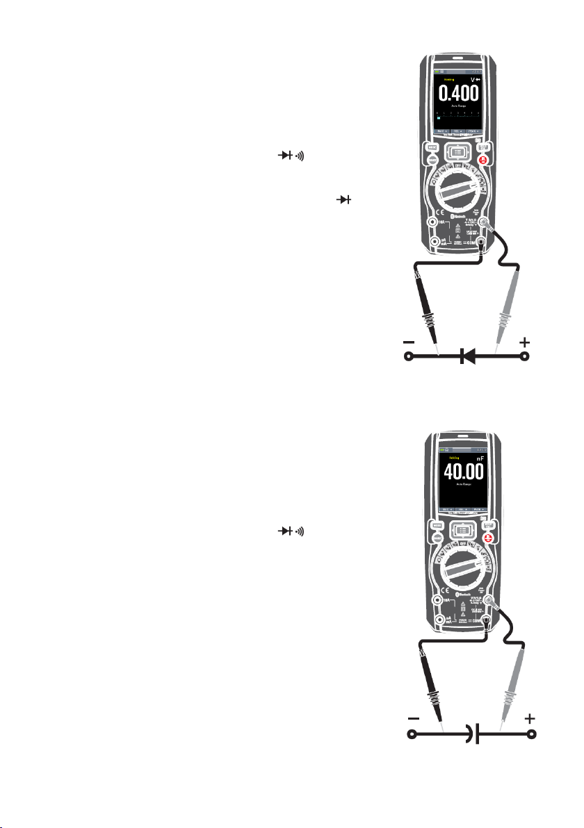
4.7 Diode Test
WARNING: To avoid electric shock, disconnect power to the
unit under test and discharge all capacitors before taking any
diode tests. Remove the batteries and unplug the line cords.
- Set the function switch to the Ω CAP position.
- Insert the black test lead banana plug into the
negative COM jack and the red test lead banana
plug into the positive V jack.
- Press the MODE key to switch the Diode functions.
- Forward voltage will typically indicate 0.400 to
3.000V. Reverse voltage will indicate “OL”. Shorted
devices will indicate near 0V and an open device
will indicate “OL” in both polarities.
4.8 Capacitance Measurements
WARNING: To avoid electric shock, disconnect power to the
unit under test and discharge all capacitors before taking any
capacitance measurements. Remove the batteries and
unplug the line cords.
- Set the function switch to the Ω CAP position.
- Insert the black test lead banana plug into the
negative COM jack. Insert the red test lead banana
plug into the positive V jack.
- Press the MODE key to switch the Capacitance
functions.
- Read the capacitance value in the Display
-50-
Page 51

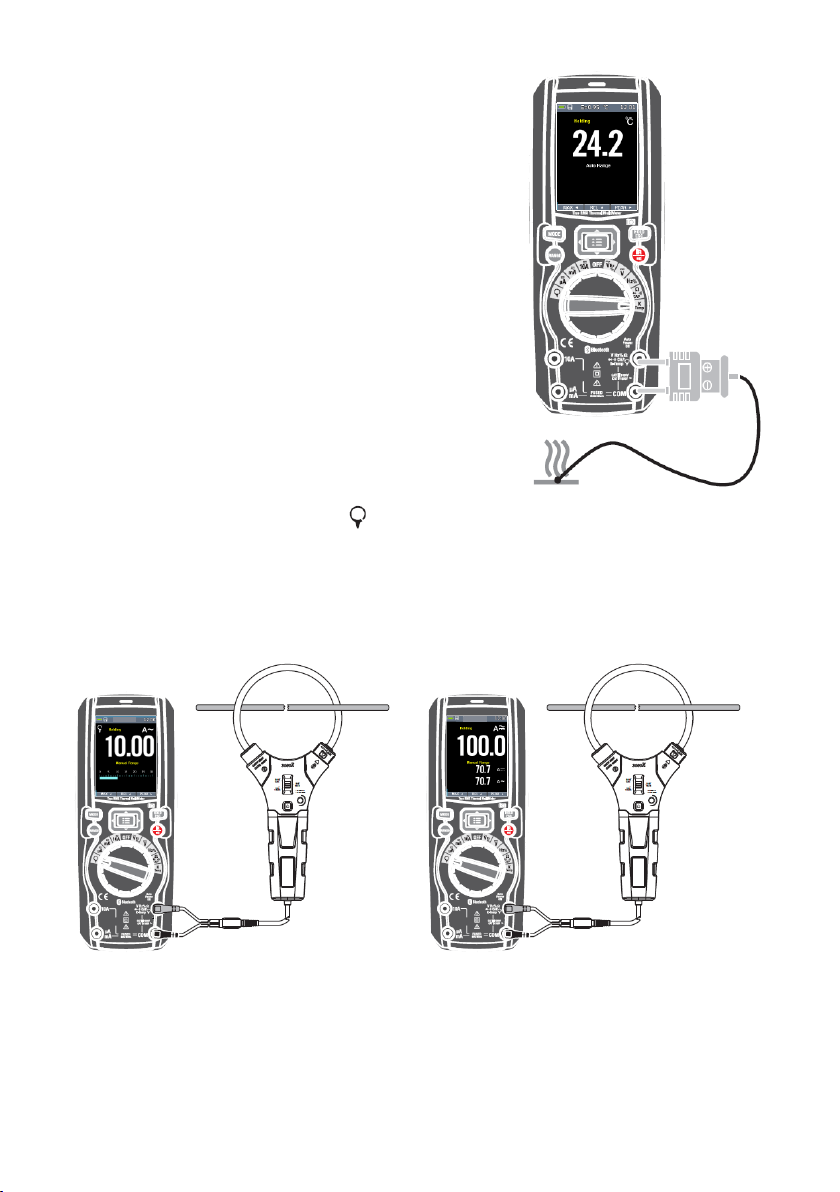
4.9 Temperature Measurements
- Set the function switch to the TEMP (°C or
°F) position.
- Insert the Temperature Probe into the input
jacks, making sure to observe the correct
polarity.
- Read the temperature in the display.
- Press the MODE key to switch the Unit (°C or
°F).
4.10. Flexible Coil Current Measurements (AC)
- Set the function switch to the Flexible coil position.
- Insert the black test lead banana plug into the negative COM jack. Insert the
red test lead banana plug into the positive V jack.
- Read the current in the display.
- Press the RANGE key to switch between ranges:
(30 A at 100 mV/A, 300 A at 10 mV/A, 3,000 A at 1 mV/A)
-51-
Page 52

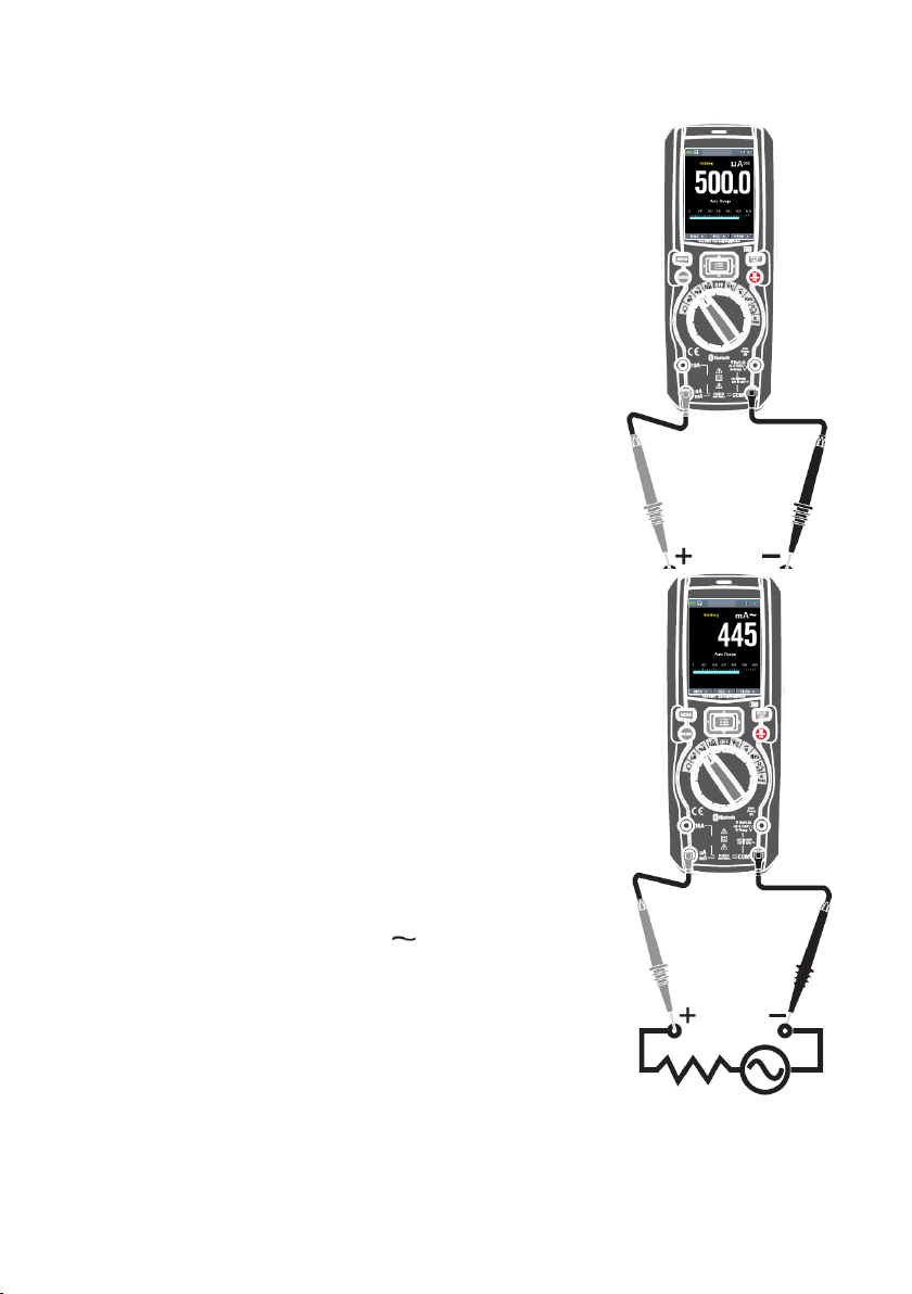
4.11. DC Current Measurements
- Insert the black test lead banana plug into the
negative COM jack.
- For current measurements up to 6000μA DC, set
the function switch to the μA position and insert the
red test lead banana plug into the μA/mA jack.
- For current measurements up to 600mA DC, set
the function switch to the mA position and insert the
red test lead banana plug into the μA/mA jack.
- For current measurements up to 10A DC, set the
function switch to the 10A position and insert the
red test lead banana plug into the 10A jack.
- Press the MODE button to indicate “ ” on the
display.
- Read the current in the display.
4.12. AC Current Measurements
CAUTION: Do not make 10A current measurements for
longer than 30 seconds. Exceeding 30 seconds may cause
damage to the meter and/or the test leads.
- Insert the black test lead banana plug into the
negative COM jack.
- For current measurements up to 6000μA AC, set
the function switch to the μA position and insert the
red test lead banana plug into the μA/mA jack.
- For current measurements up to 600mA AC, set the
function switch to the mA position and insert the red
test lead banana plug into the μA/mA jack.
- For current measurements up to 10A AC, set the
function switch to the 10A position and insert the red
test lead banana plug into the 10A jack.
- Press the MODE button to indicate “ ” on the
display.
- Read the current in the display
-52-
Page 53

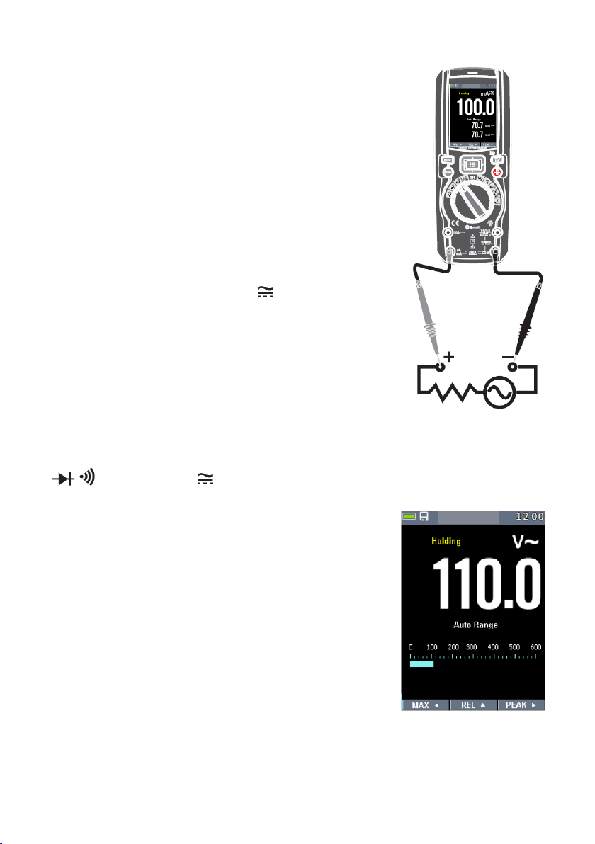
4.13 AC+DC Current Measurements
CAUTION: Do not make 10A current measurements for
longer than 30 seconds. Exceeding 30 seconds may cause
damage to the meter and/or the test leads.
- Insert the black test lead banana plug into the
negative COM jack.
- For current measurements up to 6000μA AC+DC,
set the function switch to the μA position and insert
the red test lead banana plug into the μA/mA jack.
- For current measurements up to 600mA AC+DC, set
the function switch to the mA position and insert the
red test lead banana plug into the μA/mA jack.
- For current measurements up to 10A AC+DC, set
the function switch to the 10A position and insert the
red test lead banana plug into the 10A jack.
- Press the MODE button to indicate “ ” on the
display.
- Read the current in the display.
4.14 Using RANGE
Press the RANGE key to activate the manual mode and to
disable the Autorange function. The message “Manual
Range” appears on the upper left part of the display instead
of “Auto Range”. In manual mode, press the RANGE key to
change measuring range: the relevant decimal point will
change its position. The RANGE key is not active in
positions % Temp 10A In Autorange
mode, the instrument selects the most appropriate ratio for
carrying out measurement. If a reading is higher than the
maximum measurable value, the indication “O.L” appears
on the display. Press and hold the RANGE key for more
than 1 second to exit the manual mode and restore the
Autorange mode.
-53-
Page 54

4.15 Hold Mode
To freeze the display for any function, press key HOLD.
And again press key HOLD to release freeze.
4.16 Capturing Minimum and Maximum Values
The MAX MIN Record mode captures minimum, and
maximum input values.
When the input goes below the recorded minimum value or
above the recorded maximum value, the Meter beeps and
records the new value. This mode is for capturing
intermittent readings, recording minimum and maximum
readings unattended, or recording readings while
equipment operation precludes watching the Meter. To
activate the MAX MIN mode, press soft key labeled ◄. If
the Meter is already in MAX MIN function, pressing ◄
causes the Meter to turn off MAX MIN function.
4.17 Relative Values
To activate the relative mode, press the soft key labeled ▲.
If the Meter is already in the relative function, pressing ▲
causes the Meter to turn off relative.
-54-
Page 55

4.19 Non-Contact AC Voltage Detector (100 to 1000 V AC)
WARNING: Risk of Electrocution. Before use, always test the
Voltage Detector on a known live circuit to verify proper
operation.
WARNING: Insulation type and thickness, distance from the
source, and other factors may effect operation. Always verify
live voltage using other methods before working on electrical
circuits.
- The non-contact voltage detector operates when the
meter is set to any measuring function. The detector
does not operate when Auto Power Off turns the meter
off or when the rotary function switch is set to the off
position.
- Slowly move the detector probe closer to the
conductor being tested.
- If AC voltage within the specified range is present, the
indicator light will illuminate.
NOTES: The detector is designed with high sensitivity. Static
electricity and other sources of electrical energy may randomly activate the detector.
This is normal operation. The detector only activates the indicator light when AC voltage
is present. It does not indicate the voltage level on the LCD display.
-55-
Page 56

5 Thermal Imager and DMM operation
5.1 Thermal Imager basics
In the Thermal imaging and DMM mode, the user can measure a targeted surface’s
temperature and use the Multimeter at the same time, the measured result will display
under the thermal image.
- Press the red “IR” button to activate the Thermal Imager. In Fig5-1 the thermal
image is set to color palette IRON. Select other palettes in the Menu Settings.
- Open the protective lens cover on the back of the meter.
1. The Battery capacity indicator.
2. SD card icon, if this icon is displayed, there is a SD card inserted.
3. Bluetooth icon, if this icon is displayed, the BlueTooth is active.
4. The currently selected Emissivity value. Use the Thermal Settings Menu to change
the emissivity value.
5. The temperature unit icon, Use the Thermal Settings Menu to select °C,℉,K.
6. Current time Display
7. Center cross of the Thermal imager Temperature Measurement, represents the
center spot temperature of the scene.
8. Highest temperature spot of the Thermal imager Temperature Measurement,
represents the highest spot temperature of the scene.
9. Minimum temperature spot of the Thermal imager Temperature Measurement,
represents the Minimum spot temperature of the scene.
10. Current scene of the Thermal image frame
11. Range icon of the meter
-56-
Page 57

12. Max soft button
13. REL soft button
14. PEAK soft button
15. DMM measurement is shown below the thermal image.
16. Unit of the meter
17. Lowest reading measured in the current frame
18. The Thermal scale shows the range color for thermal images. The lighter the color,
the warmer the temperature; the darker the color, the cooler the temperature.
19. Highest reading measured in the current frame.
5.2 Using the Thermal Imager
For basic operation follow these steps:
1.Set the function switch to any position.
2.Press the “IR” button to switch the thermal imager ON. Target the object by the
thermal imager len.
3.The display will show the temperature measurement in the upper left hand corner for
the targeted area along with the currently selected emissivity value.
4.In the Thermal imaging mode, the laser pointer and dispay cross hairs can be used to
assist in targeting. These tools can be switched ON or OFF in the Setting menu.
5.In the Thermal imaging mode, the highest temperature will auto marked by a red
cross, and the lowest temperature will auto marked by a blue cross, the two spots can
be switched ON or OFF in the Setting menu.
6.In the Thermal imaging mode, the meter continues to operate normally as a
Multimeter allowing any of the electrical functions to be used.
7.Press the HOLD button to hold the thermal image frame, then long press the HOLD
button, you will capture the screen and save a bitmap with measure data into SD card,
the saved bitmap later can be analysed by the PC software or smartphone APPs.
8.The thermal imager’s FOV (Field of view) is 21 by 21 degrees.
9.FOV is the largest area that your imager can see at a set distance.
10.This table lists the horizontal FOV, vertical FOV and IFOV for lens:
-57-
Page 58

IFOV (Instantaneous Field of View) is the smallest detail within the FOV that can be
detected or seen at a set distance, the unit is rad. The formula is this:
IFOV = (Pixel Size) / (Lens focal length);
D:S
theoretical
(= 1/ IFOV
) is the calculated spot size based on the pixel size of the
theoretical
Thermal Imager detector array and lens focal length.
Horizontal FOV is 21°, Vertical FOV is 21°, the IFOV is 34um/7.5mm = 4.53mrad;
D:S
theoretical
(= 1/ IFOV
theoretical
) = 220:1
D:S
measure. Typically, D:S
measure
(= 1/ IFOV
) is the spot size needed to provide an accurate temperature
measure
is 2 to 3 times smaller than D:S
measure
, which means the
theoretical
temperature measurement area of the target need to be 2 to 3 times larger than that
determined by the calculated theoretical D:S.
-58-
Page 59

5.3 Using the Multimeter with the Thermal Imager
In IR+DMM mode, MODE key, RANGE key, HOLD key and REL Function are the same
as in DMM mode.
Capturing MAXMIN Values on IR+DMM mode
1. To activate the max/min mode, press the softkey
labeled◄ , and display max value.
2. If the Meter is already in the max/min function, then
Press the ◄ key to display min value, then Press the ◄ key
to display current measurement value. next press again
display max value.
3. Press and hold the ◄ key for more than 1 second to
cause the Meter to turn off max/min.
Capturing Peak Values on IR+DMM mode
1. To activate the peak mode, press the softkey labeled ►,
and display Peak max value.
2. If the Meter is already in the peak function, then Press
the ► key to display Peak min value, then Press the ► key
to display current measurement value. next press again
display Peak max value.
3. Press and hold the ► key for more than 1 second to
causes the Meter to turn off peak.
-59-
Page 60

6 Settings Menus
6.1 Using Settings Menus
Press MENU button to open the Settings Menus, as show below.
Press UP/DOWN button to select menu item or change the value of current focus item.
Press RIGHT/MENU button to enter the submenu or set focus on the current selected
item.
Press LEFT button to return to the previous menu.
If want to exit settings menus, can press MODE/RANGE/HOLD/IR button or press LEFT
button in root menu.
6.2 Settings Details
Palette mode
Thermal imager has five kinds of palette, such as:
Press RIGHT/MENU button to select one of the display color palettes.
6.3 Temp Unit
Press RIGHT/MENU button to set focus on this option and the color of option value will
change to black . In focus state, use the RIGHT/MENU button to toggle ℃, ℉ and
K, use LEFT/RIGHT/MENU button to exit focus state and the color of option value will
change white .
-60-
Page 61

6.4 Measure
Press RIGHT/MENU button to enter measure menu.
Two selections are available: HOT POINT and COLD
POINT. Press RIGHT/MENU button to set cur select item on
or off.
Hot point: This option enables thermal imager automatically
detect the highest temperature point.
Cold point: This option enables thermal imager
automatically detect the lowest temperature point.
6.5 Emissivity
Press RIGHT/MENU button to set focus on this option. In focus state, use UP /DOWN
button to increase or decrease emissivity's value, use LEFT/RIGHT/MENU button to exit
focus state. The available range is 0.01 to 0.99 in 0.01 steps.
6.6 Language
Press RIGHT/MENU button to enter language menu.
Three options are available: Simplified Chinese, Traditional
Chinese and English.
Use UP/DOWN button to select language and use
RIGHT/MENU button to set selected language to be valid.
6.7 Setup
Press RIGHT/MENU button to enter Setup menu.
Five options are available: Beep, Bluetooth, Laser, Brightness and Auto Off.
Beep:Use RIGHT/MENU button to set beep on or off.
Bluetooth: Use RIGHT/MENU button to set bluetooth power
on or off.
Laser: Use RIGHT/MENU button to set laser pointer on or
off.
-61-
Page 62

Brightness: Press RIGHT/MENU button to set focus on this option. In focus state, use
UP/DOWN button to change LCD's brightness, use LEFT/RIGHT/MENU button
to exit focus state. The available brightness's range is 100% to 10% in 10% steps.
Auto Off: Press RIGHT/MENU button to set focus on this option. In focus state, use
UP/DOWN button to choose the time period after which the meter enters the sleep
mode
6.8 Bluetooth Connect
4. Turn on the Bluetooth function on the instrument.
5. Turn on the Bluetooth of smartphone,
press the icon Thermview+ and enter
the home interface. Then press
Connect Device icon on the Home
interface, Bluetooth device name will
appear.
6. Touch the device name listed in
Bluetooth devices list to connect to the
device.
-62-
Page 63

The detail information about Thermview+, please refer to Thermview+ APP help file.
Thermview+ for Android:
Please search in Google Play with keyword
“Thermview+”, download and run.
Thermview+ for iOS:
Please search in Apple store with keyword
“Thermview+”, download and run.
-63-
Page 64

6.9 Time/Date
Press RIGHT MENU button to enter time menu. In this
menu, year, month, day, hour, minute and time format can
be set. The changes take effect after exiting settings
menus.
6.10 Photo
Press RIGHT/MENU button to enter photo menu.
Two options are available: Photo Review and Delete Photo.
Photo Review: Press RIGHT/MENU button to enter image
browser function, and exit settings menus immediately.
Delete Photo: After Press RIGHT/MENU button, dialog box
will be displayed as show below.
Warning: Select 'YES', will delete all the photos on the
memory card which were captured by user.
-64-
Page 65

6.11 Sys Info
Press RIGHT MENU button to enter system information
menu. This menu contains software version, hardware
version and thermal imager version.
6.12 Factory Reset
When select Factory Set option, after press RIGHT/MENU
button, the dialog box will be displayed as show below.
Select 'YES' button, system parameter will be reset.
-65-
Page 66

6.13 Record Measurements
With a measurement on the display (Fig130), press Button key Menu to enter the
instrument’s general menu (Fig131). The screen is shown on the display. Press the
Button ▲ or ▼ key to select Record Item. Press the Button ▶ Enter Record
Menu(Fig132).
In Record Menu. Press the Button ▲ or ▼ key to select Sample Interval Item or
Duration Item. Press the Button ▶ Enter Record setting. Then Press the Button▲ or ▼
key to adjust time.
(Fig133)Setting of sampling interval from 1s to 59min:59s.
(Fig134)Setting of recording duration, from 1min to 9h:59min.
-66-
Page 67

In Record Menu. Press the Button ▲ or ▼ key to select
Start record Item.
Press the Button ▶ Enter Save Record measurement
(Fig135). In Save Record measurement, Press the Button ▶
to stop record. And Press the Button ▲ Save.
In Record Menu. Press the Button ▲ or ▼ key to select
Review Item. Press the Button ▶ Enter View Record
measurement (Fig136).
Press the Button MODE key to Trend record (Fig137). And
Press the Button ◄ or ▶ key to select previous record
measurement or next record measurement. And press the
Button ESC key to exit view record measurement.
-67-
Page 68

In Record View Display, Press the Button ◄ or ▶ to move
the cursor on the graph. And the Button ▲ to activate the
Zoom function of the graph
In Record Menu. Press the Button ▲ or ▼ key to select
Delete all Recordings Item (Fig139). Press the Button ▶
Enter Delete Box. And select Yes or No.
-68-
Page 69

7 Image Browser
In Image Browser mode. User can browse the
pictures in the memory card.
Press LEFT/RIGHT button to select prev or next
picture. Press any other keys to
exit Image Browser mode.
1.LEFT key instruction..
2.Current displayed picture's filename.
3.RIGHT key instruction.
4.Picture display area.
How to capture screen
When in DMM mod or Thermal imaging + DMM mode, use HOLD button to enter hold
mode, as show below. Then press
UP button to capture screen. After saving to TF card completly, multimeter will exit hold
mode.
-69-
Page 70

8 Technical Specifications
Field of view (FOV) / Minimum focus distance
21° x 21°/ 0.5m
Spatial resolution (IFOV)
4.53mrad
IR resolution
80 × 80 pixels
Thermal sensitivity/NETD
<
0.1°C @ +30°C (+86°F) / 100 mK
Image frequency
50Hz
Focus mode
Focus free
Focal length
7.5mm
Focal Plane Array (FPA)/Spectral range
Uncooled microbolometer / 8–14 µm
Object temperature range
–20°C to +260°C (–4°F to +500°F)
Accuracy
±3°C (±5.4°F) or ±3% of reading (Environment temperature
10℃-35°C, object temperature >0°C. )
Range
Resolution Accuracy
Input impedance
Protection against overcharge
600.0mV
0.1mV
±(0.09%reading + 5digits)
>10MΩ
1000VDC/ACrms
6.000V
0.001V
60.00V
0.01V
600.0V
0.1V
±(0.2%reading + 5digits)
1000V
1V
Range
Resolution
Accuracy
(*)
Protection against overcharge
(50Hz÷60Hz)
(61Hz÷1kHz)
6.000V
0.001V
±(0.8%reading+5digits)
±(2.4%reading+5dgt)
1000VDC/ACrms
60.00V
0.01V
600.0V
0.1V 1000V
1V
Range
Resolution
Accuracy (50Hz÷1kHz)
Input impedance
Protection against overcharge
6.000V
0.001V
±(2.4%reading +20dgt)
>10MΩ
1000VDC/ACrms
60.00V
0.01V
600.0V
0.1V
1000V
1V
8.1 Thermal Imager
Accuracy calculated as [%reading + (num. digits*resolution)] at 18°C ÷ 28°C <75%HR
DC Voltage
AC TRMS Voltage
(*) Accuracy specified from 10% to 100% of the measuring range,
sine wave.
Accuracy PEAK function: ±10%rdg, PEAK response time: 1ms
Input impedance: >9MΩ;
AC+ DC TRMS Voltage
-70-
Page 71

DC Current
Range
Resolution
Accuracy
Protection against overcharge
600.0uA
0.1uA
±(0.9%reading + 5digits)
Quick fuse 800mA/1000V
6000uA
1uA 60.00mA
0.01mA
600.0mA
0.1mA ±(0.9%reading + 8digits)
10.00A
0.01A ±(1.5%reading + 8digits)
Quick fuse 10A/1000V
Range
Resolution
Accuracy(*)(50Hz÷1kHz)
Protection against overcharge
600.0uA
0.1uA
±(1.2%reading + 5digits)
Quick fuse 800mA/1000V
6000uA
1uA
60.00mA
0.01mA
600.0mA
0.1mA
10.00A
0.01A ±(1.5%reading + 5digits)
Quick fuse 10A/1000V
Range
Resolution
(50Hz÷60Hz)
(61Hz÷1kHz)
Protection against overcharge
30.00A
0.01A
±(0.8%reading+5digi
ts)
±(2.4%reading+5dgt)
1000VDC/ACrms
300.0A
0.1A
3000A
1A
Function Test current
Max voltage with open circuit
<1.5mA
3.3VDC
Range
Resolution
Accuracy
Buzzer
Protection against overcharge
600.0Ω
0.1Ω
±(0.5%reading + 10dgt)
<50Ω
1000VDC/ACrms
6.000kΩ
0.001kΩ
±(0.5%reading + 5digits)
60.00kΩ
0.01kΩ
600.0kΩ
0.1kΩ
6.000MΩ
0.001MΩ
60.00MΩ
0.01MΩ
±(2.5%reading + 10dgt)
AC TRMS Current
(*) Accuracy specified from 5% to 100% of the measuring range, sine wave.
Accuracy PEAK function: ±10%rdg , AC+DC TRMS Current: accuracy (50Hz÷1kHz):
±(3.0%reading + 20dgt)
Flexible coil Current
Diode test
Resistance and Continuity test
-71-
Page 72

Frequency (electronic circuits)
Range
Resolution
Accuracy
Protection against overcharge
40.00Hz÷10kHz
0.01Hz÷0.001kHz
±(0.5%reading)
1000VDC/ACrms
Range
Resolution
Accuracy
Protection against overcharge
60.00Hz
0.01Hz
±(0.09%rdg+5digits)
1000VDC/ACrms
600.0Hz
0.1Hz
6.000kHz
0.001kHz
60.00kHz
0.01kHz
600.0kHz
0.1kHz
6.000MHz
0.001MHz
10.00MHz
0.01MHz
Range
Resolution
Accuracy
5.0%÷95.0%
0.1%
±(1.2%reading + 2digits)
Range
Resolution
Accuracy
Protection against overcharge
60.00nF
0.01nF
±(1.5%reading + 20dgt)
1000VDC/ACrms
600.0nF
0.1nF
±(1.2%reading + 8digits)
6.000uF
0.001uF
±(1.5%reading + 8digits)
60.00uF
0.01uF
±(1.2%reading + 8digits)
600.0uF
0.1uF
±(1.5%reading + 8digits)
6000uF
1uF
±(2.5%reading + 20dgt)
Range
Resolution Accuracy (*)
Protection against overcharge
-40.0°C ÷ 600.0°C
0.1°C
±(1.5%reading + 3°C)
1000VDC/ACrms
600°C ÷ 1000°C
1°C
-40.0°F ÷ 600.0°F
0.1°F
±(1.5%rdg+ 5.4°F)
600°F ÷ 1800°F
1°F
Sensitivity: 2Vrms
Frequency (electronic circuits)
Sensitivity: >2Vrms (@ 20% 80% duty cycle) and f<100kHz;
>5Vrms (@ 20% 80% duty cycle) and f>100kHz
Duty Cycle
Pulse frequency range: 40Hz÷10kHz, Pulse amplitude:±5V (100us÷100ms)
Capacity
Temperature with K-type probe
(*) Instrument accuracy without probe; Specified accuracy with stable
environmental
For long-lasting measurements, reading increases by 2°C.
temperature at ±1°C.
-72-
Page 73

Reference standards
Safety: IEC/EN61010-1
EMC: IEC/EN 61326-1
Insulation: double insulation
Pollution level: 2
Overvoltage category: CAT IV 600V, CAT III 1000V
Max operating altitude: 2000m (6562ft)
Laser: Class 2, <1mW, 630-670 nm
EN 60825-1:2014
IP65: EN 60529
Bluetooth
Type Bluetooth 4.0 Low Energy
Frequency 2379~2496 MHz
Power 0 dB
Power supply
Battery type: 1x7.4V rechargeable Li-ION battery, 1500mAh Battery
charger power supply: 100/240VAC, 50/60Hz, 12VDC, 2A
Low battery indication: symbol on the display
Auto Power Off: after 15÷60min minutes’ idling (may be disabled)
Fuses: F10A/1000V, 10 x 38mm (input 10A) F800mA/1000V,
6 x 32mm (input mA uA)
Display
Conversion: TRMS
Characteristics: colour TFT, 6000 dots with bargraph
Sampling frequency: 3 times/s
8.2. Environment
Environmental conditions for use
Reference temperature: 18°C ÷ 28°C (64°F ÷ 82°F)
Operating temperature: 5°C ÷ 40°C (41°F ÷ 104°F)
Allowable relative humidity: <80%RH
Storage temperature: -20° ÷ 60°C (-4°F ÷ 140°F)
Storage humidity: <80%RH
-73-
Page 74

All rights, also for translation, reprinting and copy of this manual or parts are reserved.
Reproductions of all kinds (photocopy, microfilm or other) only by written permission of
the publisher.
This manual is according the latest technical knowing. Technical alterations reserved.
We herewith confirm that the units are calibrated by the factory according to the
specifications as per the technical specifications.
We recommend to calibrate the unit again, after 1 year.
© PeakTech® 04/2019/Mi/HR/EHR
PeakTech Prüf- und Messtechnik GmbH – Gerstenstieg 4 - DE-22926 Ahrensburg / Germany
+49 (0) 4102 97398-80 +49 (0) 4102 97398-99
info@peaktech.de www.peaktech.de
-74-
 Loading...