

Page 1

PeakTech
®
1885 / 1890
Bedienungsanleitung /
Operation manual
Programmierbare DC-Schaltnetzteile /
Programmable Switching Mode Power
Page 2

Inhalt
1. Wichtige Sicherheitshinweise …………………………………………………………........……. 3
2. Technische Spezifikation der Netzteil-Serie ..............................................................…... 4
3. Einleitung..........................................................................................................................……. 5
4. Bedien- und Anzeigeelemente ......................................................................................…….. 5
5. Allgemeines Arbeitsprinzip .........................................................................................……… 6
5.1. Schnellübersicht der Tastenfeldfunktionen ...........................................................……. 6
6. Bedienungsanleitung ...........................................................................................................… 7
6.1. Einstellen des Betriebsmodus ……………………………………………………………… 7
6.1.1. Ausgang Ein/Aus ...............................................................................….. 7
6.1.2. Tastenfeld und Drehschalter sperren/entsperren ..................................... 7
6.1.3. Auswahl der PC-Schnittstelle RS-485 .................................................….. 7
6.1.4. Einstellen der oberen Spannungsgrenze ..........................................……. 7
6.1.5. Ausgang beim Einschalten Ein/Aus ...................................................…… 8
6.1.5. Helligkeit der LCD Anzeige ………....................................................…… 8
6.1.5. SCPI Funktion aktivieren / deaktivieren .............................................…… 8
6.2. Grundfunktionen ……………………………………………………………………………….9
6.2.1.Einstellen von Spannung & Strom über Drehschalter & UP-/DN-Tasten ...9
6.2.2.Einstellen von Spannung & Strom über Tastenfeld ................................…9
6.3. Verwenden der Programmierfunktionen ……………………………………………………10
6.3.1. Zeitprogrammierung ..................................................................................10
6.3.2. Programmlauf starten ...........................................................................….11
6.3.4. Auswählen der Voreinstellung ..............................................................….11
7. PC-Schnittstelle .........................................................................................................................12
8.1. Anschließen eines einzelnen Netzteils an den PC über RS-485 .....................................…….12
8.2. Anschlussdiagramm für mehrere Netzteile …………………………………………………12
Anhänge
Anhang A - Befehlssatz .......................................................................................… 13
2
Page 3

1. Sicherheitsvorkehrungen
Dieses Produkt erfüllt die Anforderungen der folgenden Richtlinien der Europäischen Gemeinschaft:
2014/30/EU (Elektromagnetische Verträglichkeit) und 2014/35/EU (Niederspannung) einschl.
2014/32/EU (CE-Kennzeichnung).
Zur Gewährleistung des sicheren Betriebs des Geräts und zur Vermeidung von ernsthaften
Verletzungen durch Kurzschluss (Funken) müssen die folgenden Sicherheitsvorkehrungen beachtet
werden.
Zur Betriebssicherheit des Gerätes und zur Vermeidung von schweren Verletzungen durch Stromoder Spannungsüberschläge bzw. Kurzschlüsse sind nachfolgend aufgeführte Sicherheitshinweise
zum Betrieb des Gerätes unbedingt zu beachten.
Schäden, die durch Nichtbeachtung dieser Hinweise entstehen, sind von Ansprüchen jeglicher Art
ausgeschlossen.
* Dieses Gerät darf nicht in hochenergetischen Schaltungen verwendet werden
* Vor Anschluss des Gerätes an eine Steckdose überprüfen, dass die Spannungseinstellung am
Gerät mit der vorhandenen Netzspannung übereinstimmt
* Gerät nur an Steckdosen mit geerdetem Schutzleiter anschließen
* Gerät nicht auf feuchten oder nassen Untergrund stellen.
* Ventilationsschlitze im Gehäuse unbedingt freihalten (bei Abdeckung Gefahr eines
Wärmestaus im Inneren des Gerätes)
* Keine metallenen Gegenstände durch die Ventilationsschlitze stecken.
* Keine Flüssigkeiten auf dem Gerät abstellen (Kurzschlussgefahr beim Umkippen des Gerätes)
* Gerät nicht in der Nähe starker magnetischer Felder (Motoren, Transformatoren usw.)
betreiben
* Nehmen Sie das Gerät nie in Betrieb, wenn es nicht völlig geschlossen ist.
* Defekte Sicherungen nur mit einer dem Originalwert entsprechenden Sicherung ersetzen.
Sicherung oder Sicherungshalter niemals kurzschließen.
* Gerät, Prüfleitungen und sonstiges Zubehör vor Inbetriebnahme auf eventuelle Schäden bzw.
blanke oder geknickte Kabel und Drähte überprüfen. Im Zweifelsfalle keine Messungen
vornehmen.
* Verwenden Sie ausschließlich 4mm-Sicherheitstestkabelsätze, um eine einwandfreie Funktion
des Gerätes zu gewährleisten.
* Messarbeiten nur in trockener Kleidung und vorzugsweise in Gummischuhen bzw. auf einer
Isoliermatte durchführen.
* Messspitzen der Prüfleitungen nicht berühren.
* Warnhinweise am Gerät unbedingt beachten.
* Gerät darf nicht unbeaufsichtigt betrieben werden
* Gerät keinen extremen Temperaturen, direkter Sonneneinstrahlung, extremer Luftfeuchtigkeit
oder Nässe aussetzen.
* Starke Erschütterung vermeiden.
* Heiße Lötpistolen aus der unmittelbaren Nähe des Gerätes fernhalten.
* Vor Aufnahme des Messbetriebes sollte das Gerät auf die Umgebungstemperatur stabilisiert
sein (wichtig beim Transport von kalten in warme Räume und umgekehrt)
* Messungen von Spannungen über 35V DC oder 25V AC nur in Übereinstimmung mit den
relevanten Sicherheitsbestimmungen vornehmen. Bei höheren Spannungen können
besonders gefährliche Stromschläge auftreten.
* Säubern Sie das Gehäuse regelmäßig mit einem feuchten Stofftuch und einem milden
Reinigungsmittel. Benutzen Sie keine ätzenden Scheuermittel.
* Dieses Gerät ist ausschließlich für Innenanwendungen geeignet.
* Vermeiden Sie jegliche Nähe zu explosiven und entflammbaren Stoffen.
* Öffnen des Gerätes und Wartungs – und Reparaturarbeiten dürfen nur von qualifizierten
Service-Technikern durchgeführt werden.
* Gerät nicht mit der Vorderseite auf die Werkbank oder Arbeitsfläche legen, um Beschädigung
der Bedienelemente zu vermeiden.
* Keine technischen Veränderungen am Gerät vornehmen.
* - Messgeräte gehören nicht in Kinderhände –
3
Page 4

Reinigung des Gerätes:
Vor dem Reinigen des Gerätes, Netzstecker aus der Steckdose ziehen. Gerät nur mit einem feuchten,
fusselfreien Tuch reinigen. Nur handelsübliche Spülmittel verwenden.
Beim Reinigen unbedingt darauf achten, dass keine Flüssigkeit in das Innere des Gerätes gelangt.
Dies könnte zu einem Kurzschluss und zur Zerstörung des Gerätes führen.
2. Technische Spezifikation der Netzteile
Technische Daten P 1890 P 1885
Ausgangsspannung 1-20 V DC 1-40 V DC
Ausgangsstrom 0-10 A 0-5 A
Nennausgangsleistung 200 W
Geräuschspannung (Spitze-Spitze) 30 mV
Lastregelung 300 mV 200mV
Spannungsregelung 10 mV
Eingangsspannung 100-240 V AC, 50/60 Hz
Max. Eingangsleistung 285 W
Leistungsfaktor 0,9
Display 4-stellig – Multifunktions-LCD-Display (Strom-,
Spannungs- und Leistungsmesser)
Genauigkeit ( +/- 1% + 5 Counts für Bereich V < 5V, I < 0,5A),
( +/- 1% + 2 Counts für Bereich V ≥ 5V, I ≥ 0,5A)
LCD-Maße 48 x 66 mm
Kühlung Thermostatgeregelter Lüfter
Betriebstemperatur 0- 40°C
Schutz - Überspannungsschutz,
- Strombegrenzung,
- Übertemperaturschutz.
Zulassungen CE EMC -- EN 55011, CE LVD -- EN 61010
Maße (BxHxT) 193 x 98 x 215 (mm)
Gewicht 3kg
Zubehör - Benutzerhandbuch,
- PC Windows® Software, Befehlssatz, LabView® Treiber,
- USB-Kabel, RS-485-Anschluss und ein 120 Ohm Widerstand
Optionales Zubehör - RS-485-Adapter
Anmerkung - einstellbare Spannungsobergrenze,
- Blindstromkompensation.
Spezifikationen zur Fernprogrammierung
Kommunikationsschnittstelle USB (ein Netzteil) und RS-485 (bis zu 31 Netzteile).
Fernprogrammierungsfunktionen Volle Steuerung der Netzteilfunktionen
Data Logging-Funktion Ja, mit mitgelieferter Software.
Baudrate 9600bps
Vorsichtsmaßnahmen für den Gebrauch
1. Das Gerät verfügt über eine integrierte O.V.P-Funktion (Überspannungsschutz). Wenn die
Ausgangsspannung 10% über dem eingestellten Wert liegt, wird die O.V.P. wird ausgelöst und die
Ausgangsleistung wird abgeschaltet und es erscheint die Warnung> FAULT <.
Wenn Sie diese Warnung erhalten, schalten Sie das Gerät aus und entfernen Sie alle Lasten.
Schalten Sie das Gerät wieder ein und es sollte wieder normal funktionieren.
Falls das Problem weiterhin besteht, muss das Gerät von einem Techniker untersucht werden.
2. In diesem Gerät ist ein Summer eingebaut. Der Summer ertönt, wenn Übertemperatur / Überlast /
Überspannung ausgelöst wurde.
Wenn Sie diesen Warnton hören, schalten Sie das Gerät aus und entfernen Sie alle Lasten.
Überprüfen Sie Ihre Last- und Ausgabeeinstellungen. Lassen Sie das Gerät 30 Minuten abkühlen.
Wenn Sie das Gerät erneut einschalten, sollte es den normalen Betrieb wieder aufnehmen.
Wenn das Problem weiterhin besteht, muss das Gerät von einem Techniker untersucht werden.
p-p
4
Page 5

3. Einleitung
Diese Serie an programmierbaren Schaltnetzteilen wurde für die komplette Fernprogrammierung mit
Data Logging-Funktion entwickelt. Über eine RS- 485-Schnittstelle können bis zu 31 Netzteile
angeschlossen werden. Das ist ideal für Anwendungen insbesondere mit mehreren Netzteilen, die
unterschiedliche Gruppen an Ausgangseinstellungen und Laufzeiten für sich wiederholende
Testungen erfordern.
Als Einzel-Labornetzgerät kann der Benutzer mithilfe des Anzeigefeldes alle Programmierungen und
Ausgangseinstellungen vornehmen.
Dieses Handbuch liefert komplette Befehlssätze zur Vereinfachung der Integration Ihrer eigenen
Steuerungssoftware. Diese Netzteil-Serie erfüllt die Sicherheitsnorm EN-61010 und EN-55011 EMV
für wissenschaftliche, industrielle Geräte gemäß den EU-Richtlinien.
Bewahren Sie dieses Handbuch an einem sicheren Ort auf und wenden Sie sich bei Bedarf von
optionalem Zubehör für RS-485 an Ihren Händler.
HINWEIS:
Labornetzgeräte sind nicht zum Laden von Batterien konzipiert. Eine solche Benutzung kann zu
schwerwiegenden Beschädigungen am Gerät führen, welche von Ansprüchen jeglicher Art
ausgeschlossen sind.
4. Bedien- und Anzeigeelemente
1. Drehschalter (JOG)
2. Auf- & Ab-Tasten (UP/DN)
3. Dualfunktions-Steuertasten
4. Ausgangsbuchse Minus (Blau)
5. Ausgangsbuchse GND (Grün) (an Gehäuse angeschlossen).
6. Ausgangsbuchse Plus (Rot)
7. Ein-/Aus-Schalter
8. AC 100-240 V AC Steckdose mit Eingangssicherung.
9. USB Port
10. RS-485 Port
5
Page 6

5. Allgemeines Arbeitsprinzip
Tasten
Funktion
Abschnitt
Nummerntasten, AUF/AB Tasten und Drehrad
thru
Drücken für numerischen Werte
6.2.2
Drücken zum erhöhen numerischer Werte
6.2.1
Drücken zum verringern numerischer Werte
6.2.1
Jog Wheel
Drehen zum ändern von Strom- und Spannungswerten
6.2.1
Duale Funktionstasten
Shift drücken für zweite Funktionsebene der Tasten
Jegliche Eingabe beenden und zur normalen Funktion zurück
bis
Voreingestellte Programmfunktionen aufrufen
Nutzen Sie um voreingestellte Programme zu beenden
Nutzen Sie bis um den Speicherort des voreingestellten
Programms auszuwählen und zur Bestätigung
6.3.1
6.3.3
Drücken Sie und für das RS-485 Menü
6.1.3
Drücken Sie und um die Tastensperre zu
aktivieren / deaktivieren
6.1.2
Zum bestätigen der durchgeführten Einstellungen drücken
Drücken Sie und um den Ausgang ein- und
auszuschalten
6.1.1
Ausgang beim Einschalten aktivieren
6.1.5
Ausgang beim Einschalten deaktivieren
6.1.5
Spezialfunktion
Maximale Spannungsbegrenzung festlegen
Nutzen Sie bis für die Eingabe numerischer Werte
Drücken Sie zur Bestätigung
6.1.4
Einstellung zwischen Spannung (Vset) und Strom (Iset)
umschalten
Hinweis: Dieser Abschnitt enthält einen zusammenfassenden Überblick über das Gerät. Lesen Sie
diesen Abschnitt, wenn Sie schnell starten möchten.
5.1. Schnellübersicht der Tastenfeldfunktionen
Das vorderseitige Tastenfeld ist folgendermaßen angeordnet:
(1) Zifferntasten, UP/DOWN-Tasten und Drehschalter
(2) 4 Dualfunktions-Steuertasten
Die Anzeigefeldfunktionen lassen sich folgendermaßen zusammenfassen:
6
Page 7

Aktion
LCD-Display
Beschreibung
1.
drücken
Ausgang AKTIVIERT
2.
drücken
Ausgang DEAKTIVIERT
Aktion
LCD-Display
Beschreibung
1.
drücken
Tastenfeld und Drehschalter gesperrt.
2.
drücken
Tastenfeld und Drehschalter entsperrt.
Aktion
LCD-Display
Beschreibung
1.
Erst
dann drücken
485
001
Zugriff auf Auswahl der RS-485 Adresse
2.
bis
Adresse von 1 bis 255 mit numerischen Tasten
festlegen
3.
drücken
Zur Bestätigung diese Taste drücken.
Aktion
LCD-Display
Beschreibung
1.
Erst
dann drücken
OVER V
25,6
Zugriff auf die Einstellung der
Spannungsobergrenze.
In diesem Beispiel ist die aktuelle
Spannungsobergrenze 25,6 V.
2.
bis
Zur Eingabe der gewünschten Spannung.
3.
drücken
Zur Bestätigung diese Taste drücken.
SHIFT
LOCK/UNLOCK
SHIFT
RS-485
ENTER
SHIFT
0
ENTER
9
0
O/P ON/OFF
SHIFT
0
9
6. Bedienungsanleitung
6.1. Einstellen des Betriebsmodus
6.1.1. Ausgang Ein/Aus
6.1.2. Tastenfeld und Drehschalter sperren/entsperren
6.1.3. Auswahl der PC-Schnittstelle RS-485
Hinweis: Durch Drücken von "CLEAR" können Sie jederzeit die Einstellung des Betriebsmodus
beenden zum normalen Betrieb zurückkehren.
6.1.4. Einstellen der Spannungsobergrenze
Hinweis: Durch Drücken von "CLEAR" können Sie jederzeit die Einstellung der
Spannungsobergrenze beenden und zum normalen Betrieb zurückkehren.
7
Page 8

6.1.5. Ausgang beim Einschalten Ein/Aus
Aktion
LCD-Display
Beschreibung
1.
Erst
dann UP drücken
PrUP
ON (Ein)
Dies aktiviert den Ausgang beim Einschalten des
Geräts, d.h. wenn Sie das Netzteil einschalten, ist
der Ausgang ebenfalls automatisch AN und zeigt den
zuletzt eingestellten Spannungswert.
2.
Dann
und DN
PrUp
OFF (Aus)
Dies deaktiviert den Ausgang beim Einschalten des
Geräts, d.h. der Ausgang bleibt beim nächsten
Einschalten des Geräts AUS. Aus
Sicherheitsgründen ist dies die Standardeinstellung!!
Aktion
LCD-Display
Beschreibung
1.
Drücke
dann
und drücken, um das
Helligkeitsmenü der Anzeige zu öffnen
2.
Drehen
Drehrad zur Auswahl der Helligkeit
drehen. 0 bedeutet Hitergrundbeleuchtung
aus. 9 bedeutet volle Helligkeit.
3.
Drücke
Enter zur Bestätigung drücken
Aktion
LCD-Display
Beschreibung
1.
Drücke
dann
Drücken Sie und um das
SCPI Menü zu öffnen
2.
Drehen
Wählen Sie Y oder N (Ja oder Nein) mit
dem Drehschalter aus
3.
Drücke
Enter zur Bestätigung drücken
6
Bl
SHIFT
SHIFT
6.1.6 Adjust LCD brightness
6.1.7 Adjust LCD brightness
8
Page 9
Aktion
LCD-Anzeige
Beschreibung
1.
drücken
Spannungseinstellung.
2.
Drehen
oder
UP & DN drücken
Zum Einstellen des
Spannungspegels
Drehschalter drehen oder
UP-/DN-Tasten drücken.
3.
drücken
I-set
Stromeinstellung.
4.
Drehen
oder
UP & DN drücken
Zum Einstellen des
Stroms Drehschalter
drehen oder UP-/DNTasten drücken.
5.
drücken
Zur Bestätigung diese
Taste drücken.
Aktion
LCD-Anzeige
Beschreibung
1.
2.
drücken
Gewünschte Spannung eingeben durch
Drücken der Tasten bis
Zum Start der
Spannungseinstellung
diese Taste drücken.
Einstellen der Spannung
durch Drücken der
Zifferntasten des
Zahlenfeldes.
3.
4.
drücken
Gewünschten Strom eingeben durch
Drücken der Tasten bis
Zum Start der
Stromeinstellung diese
Taste drücken.
Einstellen des Stroms
durch Drücken der
Zifferntasten des
Zahlenfeldes.
5.
drücken
Zur Bestätigung der
Spannungs- und
Stromeinstellungen Enter
drücken.
0
9
0
9
ENTER
ENTER
ENTER
ENTER
ENTER
ENTER
6.2. Grundfunktionen
6.2.1. Einstellen von Spannung & Strom über Drehschalter und UP-/DN-Tasten
6.2.2. Einstellen von Spannung & Strom über Tastenfeld
Hinweis: Durch Drücken von "CLEAR" können Sie jederzeit die Einstellung von Spannung und
Strom beenden und zum normalen Betrieb zurückkehren.
9
Page 10

6.3. Verwenden der Programmierfunktionen
Aktion
LCD-Anzeige
Beschreibung
1.
Drücke
dann
Drücken Sie und zur Eingabe
der Stufe für das Zeitprogramm.
2.
Nutze
oder
bis
Drehrad oder numerische Tasten nutzen, um
die Stufe des Zeitprogramm auszuwählen.
3.
drücke und
Up und Down Tasten nutzen, um die
verschiedenen Einstellungen des
Zeitprogramms durchzuschalten. Der
ausgewählte Teil blinkt als Indikation zur
Änderung.
4.
Nutze
oder
bis
Drehrad oder numerische Tasten zur
Einstellung der Strom-, Spannungs- oder
Zeitwerte nutzen.
5.
Drücke
Enter zur Bestätigung drücken.
6.3.1. Zeitprogrammierung
Hinweis: Durch Drücken von "CLEAR" können Sie jederzeit das Zeitprogramm beenden und
zum normalen Betrieb zurückkehren.
10
Page 11

6.3.2. Programmlauf starten
Action
LCD Display
Description
1.
Press
Then
Press and to enter in run menu.
2.
Use
or
thru
Use JOG or numbering keypad select number
of steps to be run start from step 0.
The minimum steps to be run is 2.
3.
Press
Press this key next to set number of cycle to
be run.
4.
Use
or
thru
Use JOG or numbering keypad select number
of cycle to be run.
5.
Press
Press this key to start running
6.
Press this key terminate the program running
anytime.
Aktion
LCD-Anzeige
Beschreibung
1.
Drücke
dann bis
Drücken Sie und dann bis
um die Voreinstellung auszuwählen.
z.B. + für die Voreinstellung 4
2.
Drehe
und
Drehrad für die V- und I-Einstellung des
Preset einzusetellen, wenn gewünscht
3.
Drücke
Taste zur Bestätigung drücken
4.
Drücke
dann
Drücken Sie und um das
Voreinstellungsprogramm zu verlassen.
02
rVMP
Hinweis: Durch Drücken von "CLEAR" können Sie jederzeit das Zeitprogramm beenden und zum
normalen Betrieb zurückkehren.
6.3.4. Auswählen der Voreinstellung
Hinweis: Durch Drücken von "CLEAR" können Sie jederzeit die Auswahl von Voreinstellungen beenden
und zum normalen Betrieb zurückkehren.
11
Page 12

7. Bedienungsanleitung PC-Schnittstelle
USB to RS-485 Adapter
(Optional Accessory)
Connect to
USB to RS-485 Adapter
(Optional Accessory)
USB
Dieser Abschnitt zeigt den Anschluss von:
einem Netzteil über die RS-232-Schnittstelle
2 oder mehr (bis zu 31) Netzteilen über die RS-485-Schnittstelle.
7.1. Anschließen mehrerer Netzteile an den PC über RS-485
Verwenden Sie bei mehreren anzuschließenden Netzteilen die RS-485-Schnittstelle über den RS-485Anschluss auf der Rückseite der Netzteile. Bis zu 31 Netzteile können über die RS-485-Schnittstelle
angeschlossen werden.
Sie benötigen ein USB zu RS-485-Adapter (optionales Zubehör) und die in den Abbildungen unten
dargestellten Anschlussanordnung.
8.2. Anschlussdiagramm für mehrere Netzteile.
Anschlussdiagramm für Adapter und RS-485-Anschlüsse.
Für mehr Informationen, s. Anhang B und Anhang C.
12
Page 13

Anhang
Command Code & Return Data
Description
Input Command:
SESS <address> <CR>
Return Data from Power Supply:
[OK] [CR]
Disable front panel
keypad and make PS to
Remote Mode
Input Command:
ENDS <address> <CR>
Return Data from Power Supply:
[OK] [CR]
Enable front panel
keypad and make PS to
exit Remote Mode
Input Command:
CCOM <address> <RS> {000-256} <CR>
Return Data from Power Supply:
[OK] [CR]
Change RS485
<RS> = 0 -> RS-232
<RS> = 1 -> RS-485
Input Command:
GCOM <address> <CR>
Return Data from Power Supply:
[RS] RS485 Address [??] [CR]
[OK] [CR]
Get the RS-485
address
Input Command:
GMAX <address> <CR>
Return Data from Power Supply:
Voltage [???] Current [???] [CR]
[OK] [CR]
Get maximum voltage
and current of PS
Input Command:
GOVP <address> <CR>
Return Data from Power Supply:
Voltage [???] [CR]
[OK] [CR]
Get Upper Voltage
Limit of PS
Input Command:
GETD <address> <CR>
Return Data from Power Supply:
Get Voltage & Current
reading from PS
BEFEHLSSATZ
Anmerkungen zur Verwendung des Fernprogrammiermodus
Die USB/485-Schnittstelle ist immer für den Anschluss an einen PC zur Fernprogrammierung bereit.
Befehlssatz
{ }-Befehlsdaten, [ ] – zurückgegebene Daten, [OK] = "OK", [CR] = 0 dh
???? = 30h, 30h, 30h, 30h - 39h, 39h, 39h, 39h (4 bytes data)
??? = 30h, 30h, 30h - 39h, 39h, 39h (3 bytes data)
?? = 30h, 30h – 39h, 39h (2 bytes data)
Fett – Eingabebefehl
Kursiv – vom Netzteil zurückgegebene Daten
13
Page 14

Command Code & Return Data
Description
Voltage [????] Current [????] [0] [CR]
[OK] [CR]
Voltage [????] Current [????] [1] [CR]
[OK] [CR]
PS in CV mode
PS in CC mode
Input Command:
GETS <address> <CR>
Return Data from Power Supply:
Voltage [???] Current [???] [CR]
[OK] [CR]
Get Voltage & Current
Set Value from PS
Input Command:
GETM <address> <CR>
Return Data from Power Supply:
Memory 1 Voltage [???] Current [???] [CR]
Memory 2 Voltage [???] Current [???] [CR]
. . . . .
. . . . .
. . . . .
Memory 9 Voltage [???] Current [???] [CR]
[OK] [CR]
Get All Preset Memory
Values from PS
Input Command:
GETM <address> location {1-9} <CR>
Return Data from Power Supply:
Voltage [???] Current [???] [CR]
[OK] [CR]
Get Memory from
Specific Preset of PS
Input Command:
GETP <address> <CR>
Return Data from Power Supply:
Program 00 Voltage [???] Current [???] Minute [??] Second [??] [CR]
Program 01 Voltage [???] Current [???] Minute [??] Second [??] [CR]
. . . . . . .
. . . . . . .
. . . . . . .
Program 19 Voltage [???] Current [???] Minute [??] Second [??] [CR]
[OK] [CR]
Get all the Timed
Program Memory of PS
Input Command:
GETP <address> program {00-19} <CR>
Return Data from Power Supply:
Voltage [???] Current [???] Minute [??] Second [??] [CR]
[OK] [CR]
Get Timed Program
Memory from Specific
Program of PS
Input Command:
GPAL <address> [CR]
Return Data from Power Supply:
Reading voltage [####] V [ON]
Reading current [####] A [ON]
Reading watt [####] W [ON]
Get LCD Display
Information
14
Page 15

Command Code & Return Data
Description
Timer minute [####] second [##] timer [ON] colon [ON] m [ON] s [ON]
Setting voltage [###] V-const [ON] V-bar [ON] V [ON]
Setting current [###] I-Const [ON] I-bar [ON] A [ON]
Program [#] Program [ON] P-bar [ON]
SETTING [ON] Key lock [ON] Key open [ON] FAULT [ON] Output on [ON]
Output off [ON] Remote [ON] [CR]
[OK] [CR]
Input Command:
VOLT <address> voltage {000-XXX} <CR>
Return Data from Power Supply:
[OK] [CR]
Set Voltage Level
XXX-Max. Output
Rating
Voltage = XX.X V
Current = X.XX V
Input Command:
CURR <address> current {000-XXX} <CR>
Return Data from Power Supply:
[OK] [CR]
Set Current Level
Input Command:
SOVP <address> voltage {000-XXX} <CR>
Return Data from Power Supply:
[OK] [CR]
Set Upper Voltage Limit
of PS
Input Command:
SOUT <address> 1 <CR>
Return Data from Power Supply:
[OK] [CR]
Disable Output of PS
Input Command:
SOUT <address> 0 <CR>
Return Data from Power Supply:
[OK] [CR]
Enable Output of PS
Input Command:
POWW <address> location {1-9}0 <CR>
Return Data from Power Supply:
[OK] [CR]
Enable the output
when switch on the
power supply.
Input Command:
POWW <address> location {1-9}1 <CR>
Return Data from Power Supply:
[OK] [CR]
Disable the output
when switch on the
power supply.
Input Command:
PROM <address> location {1-9} Voltage {000-XXX} Current {000-XXX} <CR>
Return Data from Power Supply:
[OK] [CR]
Set Voltage and
Current values of
Preset Memory
Input Command:
PROP <address> location {00-19} Voltage {000-XXX} Current {000-XXX}
Set Voltage, Current
15
Page 16

Command Code & Return Data
Description
Minute {00-99} Second {00-59} <CR>
Return Data from Power Supply:
[OK] [CR]
and Time period of
Timed Program
Input Command:
RUNM <address> location {1-9} <CR>
Return Data from Power Supply:
[OK] [CR]
Recall Preset Memory
1-9
Input Command:
RUNP <address> times {000-256} <CR>
Return Data from Power Supply:
[OK] [CR]
Run Timed Program
(000 = run infinite
times)
Input Command:
STOP <address> <CR>
Return Data from Power Supply:
[OK] [CR]
Stop Timed Program
Alle Rechte, auch die der Übersetzung, des Nachdruckes und der Vervielfältigung dieser Anleitung
oder Teilen daraus, vorbehalten.
Reproduktionen jeder Art (Fotokopie, Mikrofilm oder ein anderes Verfahren) nur mit schriftlicher
Genehmigung des Herausgebers gestattet.
Letzter Stand bei Drucklegung. Technische Änderungen des Gerätes, welche dem Fortschritt dienen,
vorbehalten.
Hiermit bestätigen wir, dass alle Geräte, die in unseren Unterlagen genannten Spezifikationen erfüllen
und werkseitig kalibriert geliefert werden. Eine Wiederholung der Kalibrierung nach Ablauf von 1 Jahr
wird empfohlen.
© PeakTech® 07/2019 / AW/EHR
16
Page 17

Table of Contents
1. Safety precautions ………………………………………………………….........................……… 18
2. Technical specifications ..............................................................…………………………….. 19
3. Introduction.......................................................................................................................……. 19
4. Controls and indicators ……….......................................................................................…….. 20
5. General operation principle .........................................................................................……… 21
5.1. Quick reference of keypad functions ...........................................................……….…. 21
6. User manual ..........................................................................................................................… 22
6.1. Operation modes …………………………………………………………………………….. 22
6.1.1. Output ON/OFF ...............................................................................…..... 22
6.1.2. Lock/ Unlock the Keypad and Jog Dial …………....................................... 22
6.1.3. RS-485 Address setting ……………....................................................….. 22
6.1.4. Upper voltage limit setting ……………..............................................……. 22
6.1.5. Output Enable/Disable at Power Up...................................................…… 23
6.1.6. Adjust LCD brightness ………............................................................…… 23
6.1.7. Enable/disable SCPI function …………..............................................…… 24
6.2. Basic Operation ……………………………………………………………………………...…24
6.2.1. Setting of Voltage and Current by Jog Dial and UP & DOWN Key….…….24
6.2.2. Setting of Voltage and Current Using Keypad ........................................…25
6.3. Using the Programming Features ……………………………………………..……..………25
6.3.1. Preset Program ..........................................................................................25
6.3.2. Setting of Timed Program...........................................................................26
6.3.4. Run Timed Programming.......................................................................….26
7. PC-Connection ...........................................................................................................................27
8.1. Connect Multiple Power Supplies to PC via RS-485......................................……………….….27
8.2. Connection diagram for multiple power supply….….….…………………………………...27
APPENDIX
Appendix A – Command Set .......................................................................................… 28
17
Page 18

1. Safety Precautions
This product complies with the requirements of the following European Community Directives:
2004/108/EC (Electromagnetic Compatibility) and 2006/95/EC (Low Voltage) as amended by
2004/22/EC (CE-Marking).
To ensure safe operation of the equipment and eliminate the danger of serious injury due to shortcircuits (arcing), the following safety precautions must be observed.
Damages resulting from failure to observe these safety precautions are exempt from any legal claims
whatever.
* Do not use this instrument for high-energy industrial installation measurement.
* Prior to connection of the equipment to the mains outlet, check that the available mains
voltage correspond to the voltage setting of the equipment.
* Connect the mains plug of the equipment only to a mains outlet with earth connection.
* Do not place the equipment on damp or wet surfaces.
* Do not cover the ventilations slots of the cabinet to ensure that air is able to ciculate freely
inside.
* Do not insert metal objects into the equipment by the way of ventilation slots
* Do not place water-filled containers on the equipment (danger of short-circuit in case of
knockover of the container)
* Do not operate the equipment near strong magnetic fields (motors, transformers etc.).
* Do not operate the meter before the cabinet has been closed and screwed safely as terminal
can carry voltage.
* Replace a defective fuse only with a fuse of the original rating. Never short-circuit fuse or fuse
holding.
* Check test leads and probes for faulty insulation or bare wires before connection to the
equipment.
* Please use only 4mm-safety test leads to ensure immaculate function.
* To avoid electric shock, do not operate this product in wet or damp conditions. Conduct
measuring works only in dry clothing and rubber shoes, i. e. on isolating mats.
* Never touch the tips of the test leads or probe.
* Comply with the warning labels and other info on the equipment.
* The measurement instrument is not to be to operated unattended.
* Do not subject the equipment to direct sunlight or extreme temperatures, humidity or
dampness.
* Do not subject the equipment to shocks or strong vibrations.
* Keep hot soldering irons or guns away from the equipment.
* Allow the equipment to stabilize at room temperature before taking up measurement
(important for exact measurements).
* Use caution when working with voltages above 35V DC or 25V AC. These Voltages pose
shock hazard.
* Periodically wipe the cabinet with a damp cloth and mid detergent. Do not use abrasives or
solvents.
* The meter is suitable for indoor use only
* Do not store the meter in a place of explosive, inflammable substances.
* Opening the equipment and service – and repair work must only be performed by qualified
service personnel
* Do not place the equipment face-down on any table or work bench to prevent damaging the
controls at the front.
* Do not modify the equipment in any way
* Measuring instruments don’t belong to children hands.
Cleaning the cabinet:
Prior to cleaning the cabinet, withdraw the mains plug from the power outlet.
Clean only with a damp, soft cloth and a commercially available mild household cleanser. Ensure that
no water gets inside the equipment to prevent possible shorts and damage to the equipment.
18
Page 19

Precautions For Use
1. The unit has a built-in Tracking O.V.P (Over voltage Protection) features. In the event of output
voltage becoming 10% greater than the set value, the O.V.P. will be triggered and the output power
will be cut off and >FAULT< warning appears.
When you get this warning , switch off the unit and remove all loading, switch the unit back on
again and it should resume normal operation.
In the event this problem persists, the unit must be investigated by your agent.
2. This unit has a buzzer built inside. The buzzer will sound when over temperature/ overload/ over
voltage has been triggered.
When you get this warning sound , switch off the unit and remove all loading.
Check your load and output settings.
Allow the unit to cool down for 30 minutes.
If you switch on the unit again, it should resume the normal operation.
In the event of this problem persists, the unit must be investigate by your agent.
2. Technical Specifications of Power Supplies
Specifications P 1890 P 1885
Output voltage 1-20 V DC 1-40 V DC
Output current 0-10 A 0-5 A
Rated Output Power 200 W
Ripple & Noise (p-p) 30 mV
Load Regulation 300 mV 200mV
Line Regulation 10 mV
Input Voltage 100-240 V AC, 50/60 Hz
Max. Input Power 285 W
Power Factor 0,9
Display Meter 4 digits – Display LCD Ammeter, Voltmeter and Power Meter
Meter´s Accuracy ( +/- 1% + 5 counts for range V < 5V, I < 0.5A),
( +/- 1% + 2 counts for range V ≥ 5V, I ≥ 0.5A)
LCD Dimension 48 x 66 mm
Cooling System Thermostatic Control Fan
Operating Temperature 0- 40°C
Protection -Tracking OVP (Over Voltage Protection),
-Current Limiting,
-Over Temperature Protection.
Approvals CE EMC -- EN 55011, CE LVD -- EN 61010
Dimension (WxHxD) 193 x 98 x 215 (mm)
Weight 3kg
Accessory -User's Manual,
-PC Windows® software, Command Set, LabView® Driver,
-USB cable, RS-485 Connector and one 120ohms Resistor
Optional Accessory -USB to RS-485 Adapter
Remarks -Adjustable Upper Voltage limit,
-Power Factor Correction.
Remote Programming Specifications
Communications Interface USB (single device) and RS-485 (up to 31 Power Supplies).
Remote Programming Functionality Full control of power supply functions and data readback.
Data Logging Yes, with supplied software.
Baud Rate 9600bps
p-p
3. Introduction
This series of Programmable Switching Mode Power Supplies are designed for full remote
programming with data logging functionality. Up to 31 power supplies can be connected via RS- 485. It
is ideal for applications which require various groups of output settings and running periods for
repetitive tests especially with multiple power supplies.
The front panel allows users to all programming and output settings as a stand alone laboratory power
supply.
Full command sets are given in this manual to facilitate the integration of your own control software.
19
Page 20

This series of power supplies have obtained the safety approval EN-61010 and EN-55011 EMC
approval for scientific , industrial equipment of the CE directives.
Please keep this manual in a safe place and contact your vendor for any special requirement in
optional accessories for RS-485.
NOTE:
Laboratory Power Supplies are not designed for charging batteries. Any use of this type can cause
serious damage to the device, which are exempt from any legal claims whatever.
4. Controls and Indicators
1. Jog Dial
2. Up & Down Key
3. Dual Function Control Key
4. Black colour negative polarity output terminal
5. Green colour ground terminal (connected to chassis).
6. Red colour positive polarity output terminal.
7. Power Switch
8. AC 100-240 V AC Power Socket with input power fuse.
9. RS-232 Port
10. RS-485 Port
20
Page 21

5. General Operation Principle
Keypad
Function
Section
Number Keys, UP/DOWN Keys and Jog Wheel
thru
Press to select numerical values
6.2.2
Press to ascend the numerical values
6.2.1
Press to descend the numerical values
6.2.1
Jog Wheel
Rotate to adjust the voltage and current settings
6.2.1
Dual Function Control Keys
Press to access second function of the control keys
Press to terminate any input process and the unit will exit to normal
operation
thru
Press to use recall preset program features.
Use to exit the use of any preset program
Use thru to specify the location of preset program to be used
Use to confirm
6.3.1
6.3.3
Press and to enter RS-485 set menu
6.1.3
Press and to Lock/Unlock the Keypad and Jog
Wheel
6.1.2
Press to confirm the new settings
Press and to Enable/Disable the output
6.1.1
Press to Enable the output at power up
6.1.5
Press to Disable the output at power up
6.1.5
SPECIAL Function
Press to get to the Upper Voltage Limit Setting
Use thru to input the numerical values
Use to confirm
6.1.4
Switch between set output Voltage and output Current
Note: This section contains a condensed overview of the unit. Read this section to quickly get started.
5.1 Quick Reference of Keypad Functions
The front Keypad is organised as follow:
(1) Number Keys, UP/DOWN Keys and Jog Wheel
(2) 4 Dual Function Control Keys
The front panel functions are summarized as follow:
21
Page 22

6. User Manual
Action
LCD Display
Description
1.
Press
Then
Output ENABLE
2.
Press
Then
Output DISABLE
Action
LCD Display
Description
1.
Press
Then
Keypad and Jog Dial Locked
2.
Press
Then
Keypad and Jog Dial UnLocked
Action
LCD Display
Description
1.
Press
Then
This will enter into RS-485 address set menu.
2.
to
Use numbering keypad to key in address from
1 to 255 for RS-485 connection
3.
Press
Press this key to confirm
Action
LCD Display
Description
1.
Press
Then
This will enter into Upper Voltage Limit
Adjustment.
e.g. 25.6V present upper voltage limit.
2.
to
Use the number key to input your desired
voltage
3.
Press
Press this key to confirm
485
001
6.1 Setting Operation Modes
6.1.1. Enable/Disable Output
6.1.2 Lock/ Unlock the Keypad and Jog Dial
6.1.3 RS-485 address setting
6.1.4 Upper Voltage Limit Setting
Note : Whenever to terminate the Upper Voltage Limit Setting, press “CLEAR” to return to normal
operation.
22
Page 23

6.1.5 Output Enable/Disable at Power Up
Action
LCD Display
Description
1.
Press
Then
This will enable the output at power up.
i.e. When you switch on the power supply, the
output is also ON automatically with last set
voltage value.
2.
Press
Then
This will disable the output at power up.
i.e. The output will be OFF at next power up.
This is the default setting for safety reason !!
Action
LCD Display
Description
1.
Press
Then
Press and to enter into brightness
set menu.
2.
Rotate
Use JOG adjust LCD brightness. It has 10
level of brightness. 0 means LCD brightness
off. 9 means the most brightest.
3.
Press
Press this key to confirm
6
Bl
6.1.6 Adjust LCD brightness
23
Page 24

6.1.7 Enable/Disable SCPI
Action
LCD Display
Description
1.
Press
Then
Press and to enter into SCPI
enable/disable menu
2.
Rotate
Use JOG select between Y and N
3.
Press
Press this key to confirm
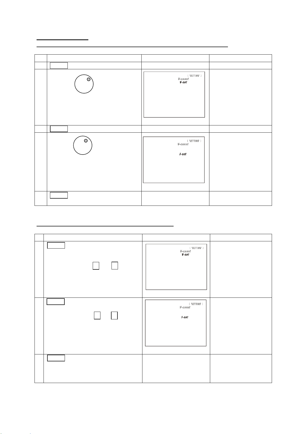
Action
LCD Display
Description
1.
Press
Press to switch between V-set and Iset.
2.
Rotate or
Press and
Rotate JOG or Press & Key to set
the voltage/current level.
Press Rotate JOG to switch between digit to
be adjust.
6.2 Basic Operation
6.2.1 Setting of Voltage and Current by Jog Dial and UP & DOWN Key
24
Page 25

6.2.2 Setting of Voltage and Current Using Keypad
Action
LCD Display
Description
1.
Press
Press to switch between V-set and Iset.
2.
to
Setting voltage/current by pressing numbers
on Keypad.
3.
Press
Press this key to confirm
Action
LCD Display
Description
1.
Press
Then thru
Press and then thru to
select Preset program.
e.g. + to select preset program 4
2.
Use
and
Use JOG and V-set/I-set adjust Voltage an d
Current setting if you want to adjust the preset
value.
3.
Press
Press this key to confirm
4.
Press
Then
Press and to exit preset
program.
Note : whenever to terminate the settings of voltage and current, press “CLEAR” to return to the
normal operation.
6.3 Using the Programming Features
6.3.1 Preset Program
Note : whenever to terminate the Timed Program, press “CLEAR” to return to the normal operation.
25
Page 26

6.3.2 Setting of Timed Program
Action
LCD Display
Description
1.
Press
Then
Press and to enter into timed
program step setting.
2.
Use
or
thru
Use JOG or numbering Keypad to select step
to be review.
3.
Press and
Use UP/DOWN key to move around voltage,
current and time setting of step.
The select part will flash to indicate it is under
modification.
4.
Use
or
thru
Use JOG or numbering keypad to modify the
voltage, current and time.
5.
Press
Press this key to confirm
Action
LCD Display
Description
1.
Press
Then
Press and to enter in run menu.
2.
Use
or
thru
Use JOG or numbering keypad select number
of steps to be run start from step 0.
The minimum steps to be run is 2.
3.
Press
Press this key next to set number of cycle to
be run.
02
rVMP
Note : whenever to terminate the Timed Program, press “CLEAR” to return to the normal operation.
6.3.3 Run Timed Programming
26
Page 27

Action
LCD Display
Description
4.
Use
or
thru
Use JOG or numbering keypad select number
of cycle to be run.
5.
Press
Press this key to start running
6.
Press this key terminate the program running
anytime.
Note : whenever to terminate the Preset Program, press “CLEAR” to return to the normal operation.
USB to RS-485 Adapter
(Optional Accessory)
Connect to
USB to RS-485 Adapter
(Optional Accessory)
USB
7. PC connection
The new SDP series can be connect use USB or RS-485. It is auto select between USB and RS-
485.
*Please do not connect both USB and RS-485 at the same.
Connect Multiple Power Supplies to PC via RS-485
For multiple power supplies, use the RS-485 Interface through the RS-485 port at rear panel of the
power supply. Up to 31 power supplies can be connected via RS-485.
You will need a USB to RS-485 Adapter and the connection shown in Figure 6a & 6b.
Figure 7a. Connection diagram for multiple power supply
Figure 7b. Connection diagram between USB Adapter and RS-485 Connectors.
27
Page 28

APPENDIX A
Command Code & Return Data
Description
Input Command:
SESS <address> <CR>
Return Data from Power Supply:
[OK] [CR]
Disable front panel
keypad and make PS to
Remote Mode
Input Command:
ENDS <address> <CR>
Return Data from Power Supply:
[OK] [CR]
Enable front panel
keypad and make PS to
exit Remote Mode
Input Command:
CCOM <address> <RS> {000-256} <CR>
Return Data from Power Supply:
[OK] [CR]
Change RS485
<RS> = 0 -> RS-232
<RS> = 1 -> RS-485
Input Command:
GCOM <address> <CR>
Return Data from Power Supply:
[RS] RS485 Address [??] [CR]
[OK] [CR]
Get the RS-485
address
Input Command:
GMAX <address> <CR>
Return Data from Power Supply:
Voltage [???] Current [???] [CR]
[OK] [CR]
Get maximum voltage
and current of PS
Input Command:
GOVP <address> <CR>
Return Data from Power Supply:
Voltage [???] [CR]
[OK] [CR]
Get Upper Voltage
Limit of PS
Input Command:
GETD <address> <CR>
Get Voltage & Current
reading from PS
COMMMAND SET
Remarks in using the Remote Programming Mode The USB/485 interface is always ready for
connection to PC for remote programming operation .
{ }- command data, [ ] - return data, [OK] = "OK", [CR] = 0dh
???? = 30h, 30h, 30h, 30h - 39h, 39h, 39h, 39h (4 bytes data)
??? = 30h, 30h, 30h - 39h, 39h, 39h (3 bytes data)
?? = 30h, 30h – 39h, 39h (2 bytes data)
<address> 30h, 30h - 3fh, 3fh (2 bytes data).
Bold – Input Command
Italic – Return Data from Power Supply
PS = Power Supply
28
Page 29

Command Code & Return Data
Description
Return Data from Power Supply:
Voltage [????] Current [????] [0] [CR]
[OK] [CR]
Voltage [????] Current [????] [1] [CR]
[OK] [CR]
PS in CV mode
PS in CC mode
Input Command:
GETS <address> <CR>
Return Data from Power Supply:
Voltage [???] Current [???] [CR]
[OK] [CR]
Get Voltage & Current
Set Value from PS
Input Command:
GETM <address> <CR>
Return Data from Power Supply:
Memory 1 Voltage [???] Current [???] [CR]
Memory 2 Voltage [???] Current [???] [CR]
. . . . .
. . . . .
. . . . .
Memory 9 Voltage [???] Current [???] [CR]
[OK] [CR]
Get All Preset Memory
Values from PS
Input Command:
GETM <address> location {1-9} <CR>
Return Data from Power Supply:
Voltage [???] Current [???] [CR]
[OK] [CR]
Get Memory from
Specific Preset of PS
Input Command:
GETP <address> <CR>
Return Data from Power Supply:
Program 00 Voltage [???] Current [???] Minute [??] Second [??] [CR]
Program 01 Voltage [???] Current [???] Minute [??] Second [??] [CR]
. . . . . . .
. . . . . . .
. . . . . . .
Program 19 Voltage [???] Current [???] Minute [??] Second [??] [CR]
[OK] [CR]
Get all the Timed
Program Memory of PS
Input Command:
GETP <address> program {00-19} <CR>
Return Data from Power Supply:
Voltage [???] Current [???] Minute [??] Second [??] [CR]
[OK] [CR]
Get Timed Program
Memory from Specific
Program of PS
Input Command:
GPAL <address> [CR]
Return Data from Power Supply:
Reading voltage [####] V [ON]
Reading current [####] A [ON]
Get LCD Display
Information
29
Page 30

Command Code & Return Data
Description
Reading watt [####] W [ON]
Timer minute [####] second [##] timer [ON] colon [ON] m [ON] s [ON]
Setting voltage [###] V-const [ON] V-bar [ON] V [ON]
Setting current [###] I-Const [ON] I-bar [ON] A [ON]
Program [#] Program [ON] P-bar [ON]
SETTING [ON] Key lock [ON] Key open [ON] FAULT [ON] Output on [ON]
Output off [ON] Remote [ON] [CR]
[OK] [CR]
Input Command:
VOLT <address> voltage {000-XXX} <CR>
Return Data from Power Supply:
[OK] [CR]
Set Voltage Level
XXX-Max. Output
Rating
Voltage = XX.X V
Current = X.XX V
Input Command:
CURR <address> current {000-XXX} <CR>
Return Data from Power Supply:
[OK] [CR]
Set Current Level
Input Command:
SOVP <address> voltage {000-XXX} <CR>
Return Data from Power Supply:
[OK] [CR]
Set Upper Voltage Limit
of PS
Input Command:
SOUT <address> 1 <CR>
Return Data from Power Supply:
[OK] [CR]
Disable Output of PS
Input Command:
SOUT <address> 0 <CR>
Return Data from Power Supply:
[OK] [CR]
Enable Output of PS
Input Command:
POWW <address> location {1-9}0 <CR>
Return Data from Power Supply:
[OK] [CR]
Enable the output
when switch on the
power supply.
Input Command:
POWW <address> location {1-9}1 <CR>
Return Data from Power Supply:
[OK] [CR]
Disable the output
when switch on the
power supply.
Input Command:
PROM <address> location {1-9} Voltage {000-XXX} Current {000-XXX} <CR>
Return Data from Power Supply:
[OK] [CR]
Set Voltage and
Current values of
Preset Memory
Input Command:
30
Page 31

Command Code & Return Data
Description
PROP <address> location {00-19} Voltage {000-XXX} Current {000-XXX}
Minute {00-99} Second {00-59} <CR>
Return Data from Power Supply:
[OK] [CR]
Set Voltage, Current
and Time period of
Timed Program
Input Command:
RUNM <address> location {1-9} <CR>
Return Data from Power Supply:
[OK] [CR]
Recall Preset Memory
1-9
Input Command:
RUNP <address> times {000-256} <CR>
Return Data from Power Supply:
[OK] [CR]
Run Timed Program
(000 = run infinite
times)
Input Command:
STOP <address> <CR>
Return Data from Power Supply:
[OK] [CR]
Stop Timed Program
This manual is according the latest technical knowing. Technical changings, which are in the interest
of progress, reserved.
We herewith confirm that the units are calibrated by the factory according to the specifications as per
the technical specifications.
We recommend to calibrate the unit again, after 1 year.
© PeakTech® 07/2019 / AW./EHR.
PeakTech Prüf- und Messtechnik GmbH – Gerstenstieg 4 –DE-22926 Ahrensburg / Germany
+49-(0) 4102-97398 80 +49-(0) 4102-97398 99
info@peaktech.de www.peaktech.de
31
 Loading...