

Peak MC-600H Installation And Service Manual
MC-600H
Motorcycle lift

CONTENTS
I. Product Features and Specifications…………………..................…….2
II. Installation requirement...…………………………..................……..…3
III. Steps of Installation...………………………….................…………..…4
IV. Exploded View………………………………………….....................….…..9
V. Test Run…….……………………………………..…….…..........................12
VI. Operation Instruction.…………………………................…..…….…...13
VII. Maintenance……………………………………..................….……….....14
VIII. Trouble shooting.……………………………….…................……….…15
IX. MC-600H parts list……..…………….………...................................….16
1
I .PRODUCT FEATURES AND SPECIFICATIONS
● Hydraulic direct-drive cylinders, designed and made on ANSI standard,
utilizing oil seal in cylinder
● Self-lubricating UHMW Polyethylene sliders and bronze bush
● Non-skid diamond platforms
● Automatic safety release system
● Optional: Width extension kit and platform extension kit
Model
Capacity
Lifting
Height
Lifting
Time
Overall
Length
Overall
Width
Minimum
Height
Gross
weight
Motor
MC-600H
600KG
1090mm
23s
2745mm
750mm
155mm
290kg
1.5HP
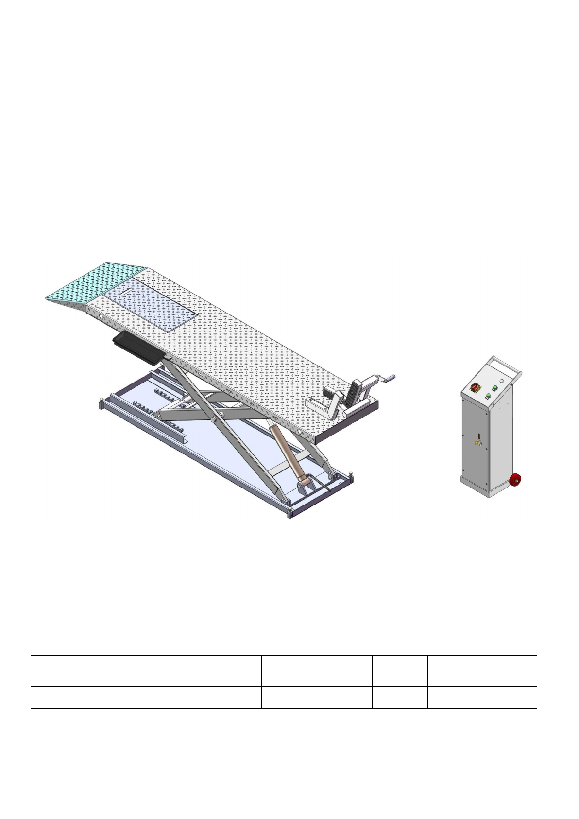
Fig.1
Motorcycle lift MC-600H:
MODEL MC-600H SPECIFICATION
2
II . INSTALLATION REQUIREMENT
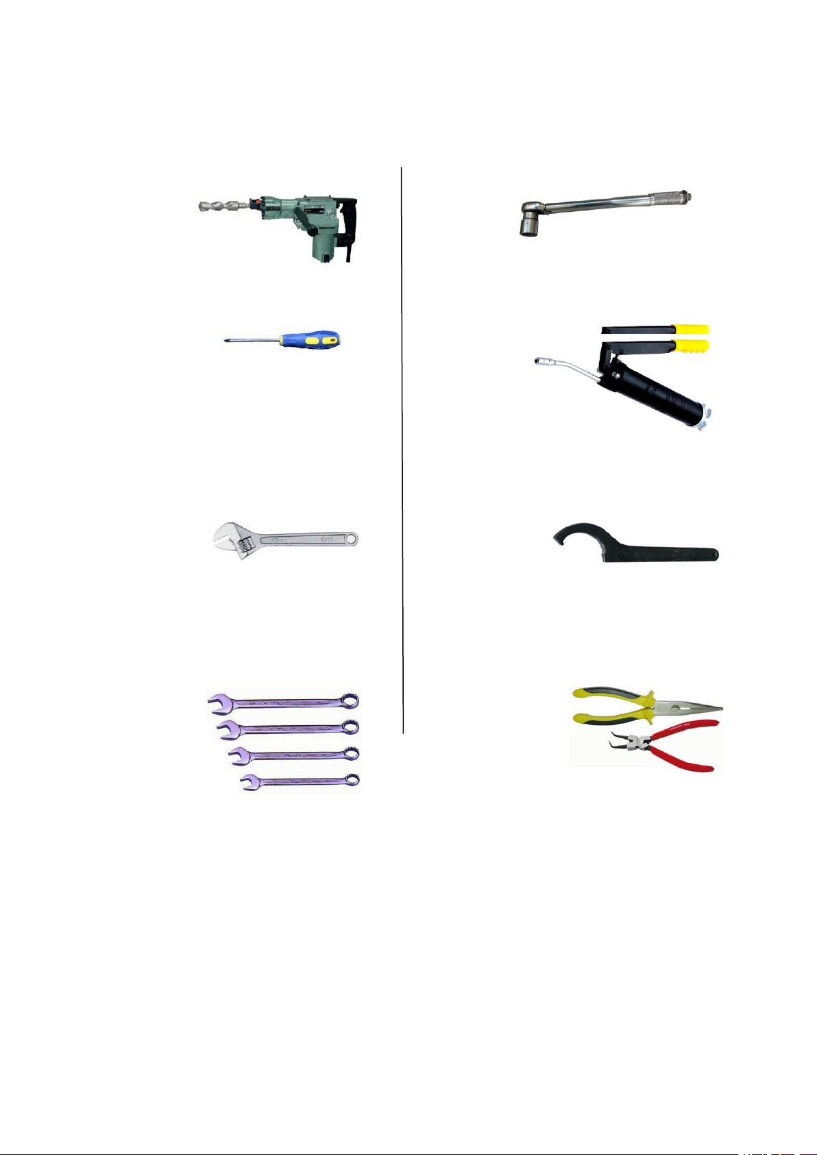
Fig.2
Pliers
Grease gun
Hook Spanner(40~42mm)
A. TOOLS REQUIRED
Rotary Hammer Drill (Φ19)
Screw
English Spanner (12")
Ratchet Spanner with Socket:(28
#
)
Wrench Set:(13
#
、15#、17#、19#)
3
B. SPECIFICATIONS OF CONCRETE
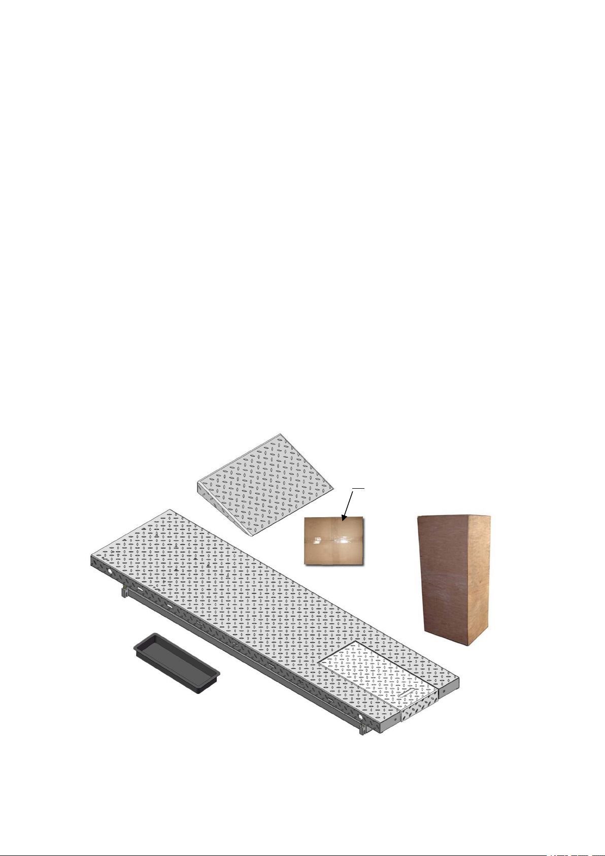
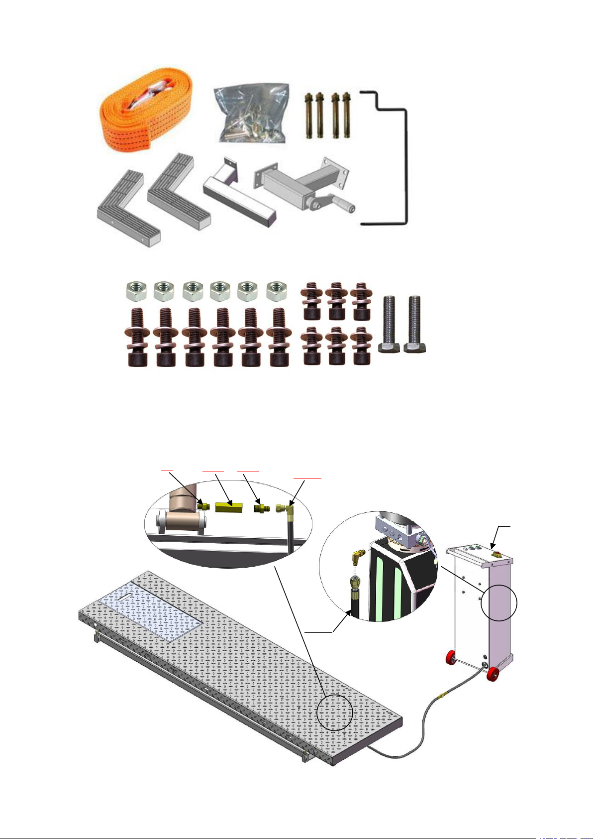
A. Check the parts before assembly to make sure all the parts are completed.
1. Packaged cargo( lift, drive-in ramp, Parts box, control cabinet). Move the parts
aside, open the outer packing and check the parts according to the shipment parts
list. see Fig.3
Fig.3
57
Specifications of concrete must be adhere to the specifications as
following. Failure to do so may result in lift and/or vehicle falling.
1. Concrete must be thickness 100mm minimum and without reinforcing steel bars,
and must be dried completely before lift installation.
2. Concrete must be of test strength 210kg/cm2minimum.
C. POWER SUPPLY
The power capacity must be more than 2.2kw, The source cable size must be
2.5mm² and in good condition of contacting with floor.
III.STEPS OF INSTALLATION
4
2. Open the parts box, check the parts according to the parts list (See Fig. 4).
Fig.4
Fig.5
Fig.6
53
53-12
51
51-1
51-2
53-12
3. Open the parts bag, check the parts according to the parts list (See Fig. 5).
B. Put the lift and control cabinet in good order and connect the oil hose, see
Fig.6
5
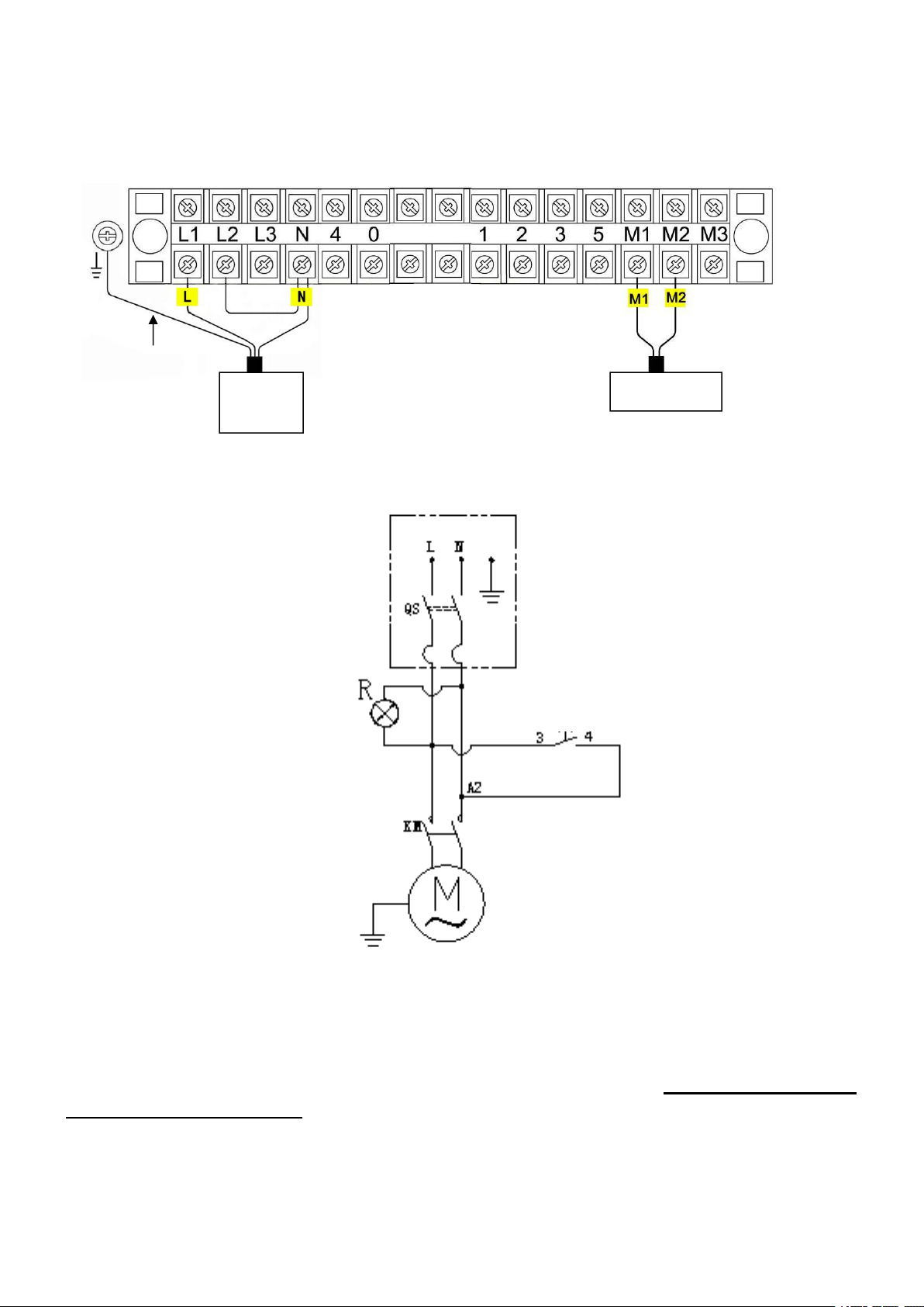
C. Install Electrical System
1. Connect the wire according to below diagram. ( Fig.7 )
Power
wire
Motor wire
Fig.7
Ground
Fig.8
3PH
Switch button
SB(UP)
2.2 Schematic circuit diagram(Fig.8)
D. Fastening all the oil hose fittings, fill the power unit with right amount
hydraulic oil ( in order to ensure the working life of hydraulic system and the
machine reach the best performance, please fill in the no.46 high quality
anti-wear hydraulic oil. )
E. Install adjustable fixing device. See Fig 9
 Loading...