

Peak IPEH-004026, IEPH-004040, IPEH-004027 User Manual
PCAN-PCI Express FD
CAN FD Interface for PCI Express
User Manual
Document version 1.2.0 (2017-06-15)

PCAN-PCI Express FD – User Manual
2
Relevant products
Product name Model Part number
PCAN-PCI Express FD Single Channel
PCAN-PCI Express FD Dual Channel
PCAN-PCI Express FD Four Channel
One CAN channel
Two CAN channels
Four CAN channels
IPEH-004026
IPEH-004027
IEPH-004040
The cover picture shows the product PCAN-PCI Express FD Four Channel. Other
product models have an identical form factor but vary in equipment.
CANopen® and CiA® are registered community trade marks of CAN in Automation
e.
v.
All other product names mentioned in this manual may be the trademarks or
registered trademarks of their respective companies. They are not explicitly marked
by “™” and “®”.
Copyright © 2017 PEAK-System Technik GmbH
Duplication (copying, printing, or other forms) and the electronic distribution of this
document is only allowed with explicit permission of PEAK-System Technik GmbH.
PEAK-System Technik GmbH reserves the right to change technical data without
prior announcement. The general business conditions and the regulations of the
license agreement apply. All rights are reserved.
PEAK-System Technik GmbH
Otto-Roehm-Strasse 69
64293 Darmstadt
Germany
Phone: +49 (0)6151 8173-20
Fax: +49 (0)6151 8173-29
www.peak-system.com
info@peak-system.com
Doc
ument version 1.2.0 (2017-06-15)

PCAN-PCI Express FD – User Manual
3
Contents
1 Introduction 5
1.1 Properties at a Glance 5
1.2 System Requirements 7
1.3 Scope of Supply 7
2 Installing the Software and the Card 8
3 Connecting a CAN Bus 10
3.1 Connection over D-Sub connector 10
3.2 Slot Bracket with D-Sub Connectors 11
3.3 Voltage Supply of External Devices 12
3.4 Activating the Daisy Chain 14
3.5 Activating the Internal Termination 18
3.6 Cabling 20
3.6.1 Termination 20
3.6.2 Example of a Connection 20
3.6.3 Maximum Bus Length 21
4 Software and API 22
4.1 Monitor Software PCAN-View 22
4.1.1 Receive/Transmit Tab 25
4.1.2 Trace Tab 27
4.1.3 PCAN-PCI Express FD Tab 28
4.1.4 Bus load Tab 29
4.1.5 Error Generator Tab 30
4.1.6 Status Bar 31
4.2 Linking Own Programs with PCAN-Basic Version
4 or Higher 32
4.2.1 Features of PCAN-Basic 33
4.2.2 Principle Description of the API 34
4.2.3 Notes about the License 35

PCAN-PCI Express FD – User Manual
4
5 Technical Specifications 36
Appendix A CE Certificate 38
Appendix B Dimension Drawing 39
Appendix C Quick Reference 40

PCAN-PCI Express FD – User Manual
5
1 Introduction
The plug-in card PCAN-PCI Express FD allows the connection of a
PC with PCI Express slots to CAN FD and CAN networks. There is
galvanic isolation of up to 500 Volts between the computer and CAN
sides. The card is available as a single, dual, or four-channel
version.
The new CAN FD standard (CAN with Flexible Data rate) is primarily
characterized by higher bandwidth for data transfer. The maximum
of 64 data bytes per CAN FD frame (instead of 8 so far) can be
transmitted with bit rates up to 12 Mbit/s. CAN FD is downwardcompatible to the CAN 2.0 A/B standard, thus CAN FD nodes can be
used in existing CAN networks. However, in this case the CAN FD
extensions are not applicable.
The monitor software PCAN-View and the programming interface
PCAN-Basic for the development of applications with CAN
connection are included in the scope of supply and support the new
CAN FD.
Device drivers exist for different operating systems, so programs
can easily access a connected CAN bus.
Tip: At the end of this manual (Appendix C) you can find a
Quick Reference with brief information about the installation
and operation of the PCAN-PCI Express FD card.
1.1 Properties at a Glance
PC plug-in card (PCI Express x1) for PCI Express slots
1, 2, or 4 High-speed CAN channels (ISO 11898-2)
Complies with CAN specifications 2.0 A/B and FD

PCAN-PCI Express FD – User Manual
6
CAN FD support for ISO and Non-ISO standard switchable
CAN FD bit rates for the data field (64 bytes max.) from 25 kbit/s
up to 12 Mbit/s
CAN FD bit rates from 25 kbit/s up to 1 Mbit/s
CAN bus connection via D-Sub, 9-pin (according to CiA® 303-1)
FPGA implementation of the CAN FD controller
NXP TJA1044GT CAN transceiver
Galvanic isolation on the CAN connection up to 500 V,
separately for each CAN channel
CAN termination can be activated through a solder jumper,
separately for each CAN channel
PCI Express data transfer via bus master DMA
DMA memory access operations with 32- and 64-bit addresses
Measurement of bus load including error frames and overload
frames on the physical bus
Induced error generation for incoming and outgoing CAN
messages
5-Volt supply to the CAN connection through a solder jumper,
e.g. for external bus converter
Extended operating temperature range from -40 to 85 °C
(-40 to 185 °F)
Note: This manual describes the use of the PCAN-PCI Express
card with Windows. You find device drivers for Linux and the
corresponding application information on the provided DVD in
the directory branch Develop and on our website at
www.peak-system.com/linux.

PCAN-PCI Express FD – User Manual
7
1.2 System Requirements
A vacant PCI Express slot in the computer (specification 2.x)
Windows 10, 8.1, 7 (32/64-bit) or Linux (32/64-bit)
1.3 Scope of Supply
Plug-in card PCAN-PCI Express FD
Slot bracket with D-Sub connectors for the CAN bus
(only four-channel version)
Device drivers for Windows 10, 8.1, 7 and Linux (32/64-bit)
CAN monitor PCAN-View for Windows
Programming interface PCAN-Basic for developing applications
with CAN connection
Programming interfaces for standardized protocols from the
automotive sector
Manual in PDF format

PCAN-PCI Express FD – User Manual
8
2 Installing the Software and
the Card
This chapter covers the software setup for the PCAN-PCI Express FD
card in Windows and the installation of the card in the computer.
Install the driver before
you install the card.
Do the following to install the driver:
1. Start Intro.exe from the supplied DVD.
The navigation program starts.
2. In the main menu, select Drivers and click on Install now.
3. Confirm the message of the User Account Control related to
"Installer database of PEAK Drivers".
The driver setup starts.
4. Follow the program instructions.
Do the following to install the card:
Attention! Electrostatic discharge (ESD) can damage or destroy
components on the card. Take precautions to avoid ESD.
1. Shut down the computer.
2. Disconnect the computer’s power supply.
3. Open the computer case.
4. Insert the PCI Express card into a vacant PCI Express slot.
5. Close the computer case.
6. Reconnect the computer power supply.
7. Turn on the computer and start Windows.

PCAN-PCI Express FD – User Manual
9
Windows detects the new hardware and completes the driver
installation.
Do the following to check the operational readiness:
1. Open the Windows Start menu.
2. Type peakcpl and press Enter .
The information window for PEAK hardware appears. The plug-in
card must be displayed in the table on the CAN Hardware tab.
PCAN-PCI Express FD – User Manual
10
3 Connecting a CAN Bus
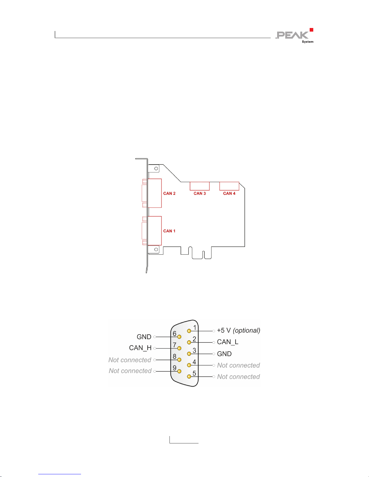
3.1 Connection over D-Sub connector
The High-speed CAN bus (ISO 11898-2) is connected to the 9-pin
D-Sub connector. The pin assignment for CAN corresponds to the
specification CiA® 303-1.
Figure 1: Position of the sockets on the four-channel card (IPEH-004040);
dual channel card (IPEH-004027) only CAN 1 and CAN 2;
single channel card (IPEH-004026) only CAN 1
Figure 2: Pin assignment of High-speed CAN;
male connector on the card (IPEH-004026/27/40)
PCAN-PCI Express FD – User Manual
11
Low power devices (e.g. bus converters) can be supplied directly
with 5 volts over pin 1 of the CAN connector. Pin 1 is not in use at
the delivery state. For more information, see the next section
63.2.
Tip: Connect a CAN bus with a different transmission standard
via a bus converter. PEAK-System offers different bus converter
modules like the PCAN-TJA1054 for a Low-speed CAN bus
according to ISO 11898-3.
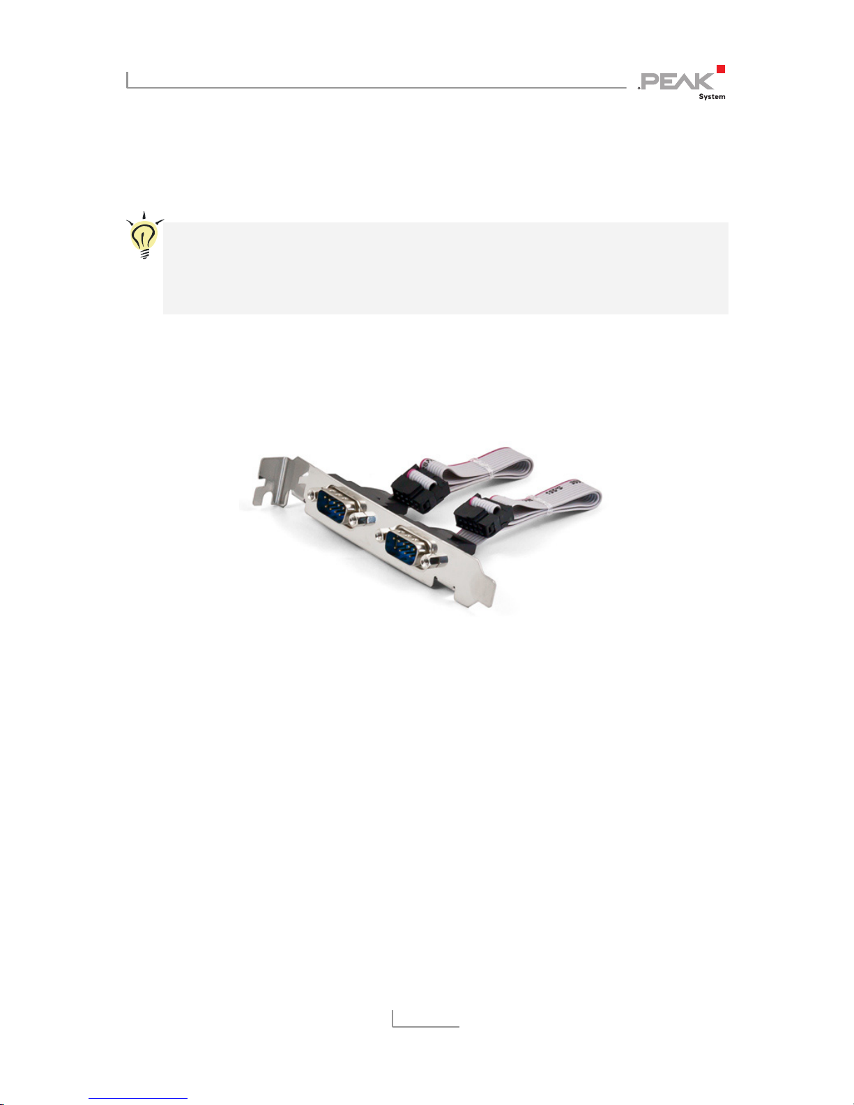
3.2 Slot Bracket with D-Sub Connectors
Figure 3: Dual channel slot bracket
Only four-channel card (IPEH-004040): To connect a CAN bus to the
four-channel card, use the supplied slot bracket. After you have
connected the cables from the slot bracket with the 10-pin sockets
of CAN port 3 and 4, you can connect the CAN busses with the DSub sockets.
PCAN-PCI Express FD – User Manual
12
3.3 Voltage Supply of External Devices
External devices with low power consumption (e.g. bus converters)
can be directly supplied via the CAN connector. With a solder bridge
per CAN channel on the PCAN-PCI Express FD board, a 5-Volt
supply can optionally be routed to pin 1 of the D-Sub connector.
The current output is limited to 50 mA.
Do the following to activate the voltage supply:
Risk of short circuit! Solder with great care to avoid unwanted
short circuits on the card.
Attention! Electrostatic discharge (ESD) can damage or destroy
components on the card. Take precautions to avoid ESD.
Set the solder bridges corresponding to the desired settings.
Figure 4 on page 13 shows the solder field positions on the fourcha
nnel card (IPEH-004040). The solder fields for the single and dual
channel versions (IPEH-004026/27) are located in the same positions
and can therefore also be taken from this figure. The table below
contains the possible settings.
Risk of short circuit! The 5-Volt supply is not protected
separately. Therefore, turn off the computer before you
connect and disconnect CAN cables or peripheral systems.
 Loading...