

Peak IPEH-003026, IPEH-003027, IPEH-003040 User Manual
PCAN-PCI Express
CAN Interface for PCI Express
User Manual
Document version 3.5.1 (2017-01-30)

PCAN-PCI Express – User Manual
2
Relevant products
Product name Model Part number Ser. no.
PCAN-PCI Express Single
Channel galv. isolated
One C
AN channel IPEH-003026
PCAN-PCI Express Dual
Channel galv. Isolated
Two CAN channels IPEH-003027
starting at
01000
PCAN-PCI Express Four
Channel galv. isolated
Four CAN channels IPEH-003040
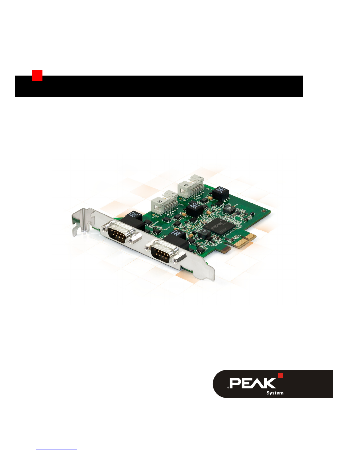
The cover picture shows the product PCAN-PCI Express Four Channel galvanic
isolated. Other product versions have an identical form factor but vary in equipment.
CANopen® and CiA® are registered community trade marks of CAN in Automation
e.
v.
All other product names mentioned in this manual may be the trademarks or
registered trademarks of their respective companies. They are not explicitly marked
by “™” and “®”.
Copyright © 2017 PEAK-System Technik GmbH
Duplication (copying, printing, or other forms) and the electronic distribution of this
document is only allowed with explicit permission of PEAK-System Technik GmbH.
PEAK-System Technik GmbH reserves the right to change technical data without
prior announcement. The general business conditions and the regulations of the
license agreement apply. All rights are reserved.
PEAK-System Technik GmbH
Otto-Roehm-Strasse 69
64293 Darmstadt
Germany
Phone: +49 (0)6151 8173-20
Fax: +49 (0)6151 8173-29
www.peak-system.com
info@peak-system.com
Doc
ument version 3.5.1 (2017-01-30)

PCAN-PCI Express – User Manual
3
Contents
1 Introduction 5
1.1 Properties at a Glance 5
1.2 System Requirements 6
1.3 Scope of Supply 6
2 Installing the Software and the Card 8
3 Connecting the CAN Bus 10
3.1 Connection over D-Sub connector 10
3.1.1 Slot Bracket with D-Sub Connectors 12
3.2 Voltage Supply of External Devices 13
3.3 Cabling 15
3.3.1 Termination 15
3.3.2 Example of a Connection 15
3.3.3 Maximum Bus Length 16
4 Software and API 17
4.1 Monitor Software PCAN-View 17
4.1.1 Receive/Transmit Tab 19
4.1.2 Trace Tab 21
4.1.3 PCAN-PCI Express Tab 22
4.1.4 Status Bar 22
4.2 Linking Own Programs with PCAN-Basic 23
4.2.1 Features of PCAN-Basic 24
4.2.2 Principle Description of the API 25
4.2.3 Notes about the License 26
5 Technical Specifications 27
Appendix A CE Certificate 29

PCAN-PCI Express – User Manual
4
Appendix B Dimension Drawing 30
Appendix C Quick Reference 31

PCAN-PCI Express – User Manual
5
1 Introduction
The PCAN-PCI Express card enables the connection of a PC with
PCI Express slots to CAN networks. There is galvanic isolation of up
to 500 Volts between the computer and CAN sides. The card is
available as a single, dual, or four-channel version.
The monitor software PCAN-View and the programming interface
PCAN-Basic for the development of applications with CAN
connection are included in the scope of supply.
Device drivers exist for different operating systems, so programs
can easily access a connected CAN bus.
Tip: At the end of this manual (Appendix C) you can find a
Quick Reference with brief information about the installation
and operation of the PCAN-PCI Express card.
1.1 Properties at a Glance
PC plug-in card (PCIe x1) for PCI Express slots
1, 2 or 4 High-speed CAN channels (ISO 11898-2)
Bit rates from 5 kbit/s up to 1 Mbit/s
Compliant CAN specifications 2.0A (11-bit ID)
and 2.0B (29-bit ID)
CAN bus connection via D-Sub,
9-pin (in accordance with CiA® 303-1)
FPGA implementation of the CAN controller
(SJA1000 compatible)
NXP PCA82C251 CAN transceiver

PCAN-PCI Express – User Manual
6
Galvanic isolation on the CAN connection up to 500 V, separate
for each CAN channel
5-Volt supply to the CAN connection can be connected through a
solder jumper, e.g. for external bus converter
Extended operating temperature range from -40 to 85 °C
(-40 to 185 °F)
Note: This manual describes the use of the PCAN-PCI Express
card with Windows. You can find device drivers for Linux and
the corresponding application information on the provided DVD
in the directory branch Develop and on our website under
www.peak-system.com/linux.
1.2 System Requirements
A vacant PCI Express slot in the computer
Operating system Windows 10, 8.1, 7 (32/64-bit)
or Linux (32/64-bit)
1.3 Scope of Supply
PCAN-PCI Express card
Slot bracket with D-Sub connectors for the CAN bus
(only four-channel version)
Device drivers for Windows 10, 8.1, 7 and Linux (32/64-bit)
CAN monitor PCAN-View for Windows
Programming interface PCAN-Basic for developing applications
with CAN connection

PCAN-PCI Express – User Manual
7
Programming interfaces for standardized protocols from the
automotive sector
Manual in PDF format

PCAN-PCI Express – User Manual
8
2 Installing the Software and
the Card
This chapter covers the software setup for the PCAN-PCI Express
card in Windows and the installation of the card in the computer.
Install the driver before
you install the card.
Do the following to install the driver:
1. Start Intro.exe from the root directory of the DVD.
The navigation program starts.
2. Select in the main menu Drivers and click on Install now.
3. Confirm the message of the User Account Control related
"Installer database of PEAK Drivers".
The driver setup starts.
4. Follow the program instructions.
Do the following to install the card:
Attention! Electrostatic discharge (ESD) can damage or destroy
components on the card. Take precautions to avoid ESD.
1. Four-channel version only: Connect the 10-pin connector of
CAN ports 3 and 4 with a cable from the slot bracket.
2. Shut down the computer.
3. Disconnect the computer’s power supply.
4. Open the computer case.
5. Insert the PCI Express card into an available PCI Express
slot.

PCAN-PCI Express – User Manual
9
6. Four-channel version only: The additional slot bracket with
connectors used by the four-channel version needs a further
place.
7. Insert the PCI Express card into an available PCI Express
slot.
8. Close the computer case.
9. Reconnect the computer power supply.
10. Turn on the computer and start Windows.
Windows detects the new hardware and completes the driver
installation.
Do the following to check the operational readiness:
1. Open the Windows Start menu.
2. Type peakcpl and press Enter .
The information window for PEAK hardware appears. The plug-in
card must be displayed in the table on the CAN Hardware tab.
PCAN-PCI Express – User Manual
10
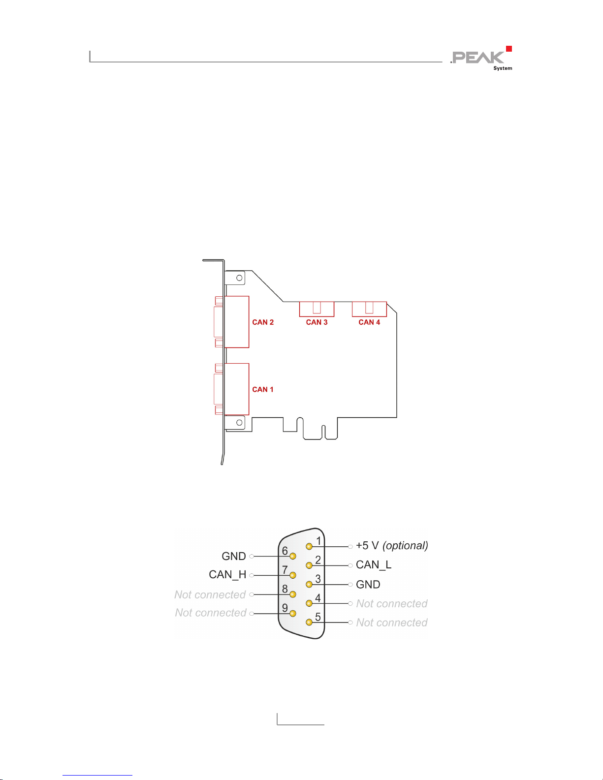
3 Connecting the CAN Bus
3.1 Connection over D-Sub connector
A High-speed CAN bus (ISO 11898-2) is connected to the 9-pin
D-Sub connector. The pin assignment for CAN corresponds to the
specification CiA® 303-1.
Figure 1: Position of the sockets for the CAN connection,
CAN 3 (upper left position), CAN 4 (upper right position)
Figure 2: Pin assignment of High-speed CAN connection
(view onto a male connector on the PCAN-PCI Express card)
 Loading...