

Peak IPEH-002090, IPEH-002091, IPEH-002093, IPEH-002092 User Manual
PCAN-PC Card
CAN Interface for the PC Card Slot
User Manual
Document version 2.4.1 (2016-07-07)

PCAN-PC Card – User Manual
2
Relevant products
Product name Model Part number
PCAN-PC Card Single Channel One CAN channel IPEH-002090
PCAN-PC Card Dual Channel Two CAN channels IPEH-002091
PCAN-PC Card Single Channel
opto-decoupled
One CAN channel, galvanic
isolation for CAN connection
IPEH-002092
PCAN-PC Card Dual Channel
opto-decoupled
Two CAN channels, galvanic
isolation for CAN connections
IPEH-002093
The cover picture shows the product PCAN-PC Card Dual Channel. The Single
Channel models have an identical form factor but only one breakout cable for the
CAN connection.
CANopen® and CiA® are registered community trade marks of CAN in Automation
e.
V.
All other product names mentioned in this document may be the trademarks or
registered trademarks of their respective companies. They are not explicitly marked
by “™” and “®”.
Copyright © 2016 PEAK-System Technik GmbH
Duplication (copying, printing, or other forms) and the electronic distribution of this
document is only allowed with explicit permission of PEAK-System Technik GmbH.
PEAK-System Technik GmbH reserves the right to change technical data without
prior announcement. The general business conditions and the regulations of the
license agreement apply. All rights are reserved.
PEAK-System Technik GmbH
Otto-Roehm-Strasse 69
64293 Darmstadt
Germany
Phone: +49 (0)6151 8173-20
Fax: +49 (0)6151 8173-29
www.peak-system.com
info@peak-system.com
Doc
ument version 2.4.1 (2016-07-07)

PCAN-PC Card – User Manual
3
Contents
1 Introduction 5
1.1 Properties at a Glance 5
1.2 System Requirements 6
1.3 Scope of Supply 6
2 Installing the Software and the Card 7
3 Connecting CAN Bus 8
3.1 Connection over D-Sub Connector 8
3.2 Voltage Supply of External Devices 9
3.3 Cabling 9
3.3.1 Termination 9
3.3.2 Example of a Connection 10
3.3.3 Maximum Bus Length 10
4 Operation 12
4.1 Status LED 12
4.2 Removing the Card 12
5 Software and API 13
5.1 CAN Monitor PCAN-View for Windows 13
5.1.1 Receive/Transmit Tab 15
5.1.2 Trace Tab 17
5.1.3 PCAN-PC Card Tab 18
5.1.4 Status Bar 19
5.2 Linking Own Programs with PCAN-Basic 20
5.2.1 Features of PCAN-Basic 21
5.2.2 Principle Description of the API 22
5.2.3 Notes about the License 23
6 Technical Specifications 24

PCAN-PC Card – User Manual
4
Appendix A CE Certificate 26
Appendix B Dimension Drawing 27
Appendix C Quick Reference 28

PCAN-PC Card – User Manual
5
1 Introduction
The PCAN-ExpressCard provides a connection between a CAN bus
and a laptop or desktop PC with an ExpressCard slot. The card is
available in single and dual-channel versions. There are also galvanically separated versions which guarantee galvanic separation
up to a maximum of 300 Volts between the PC and CAN sides.
The monitor software PCAN-View and the programming interface
PCAN-Basic for the development of applications with CAN
connection are included in the scope of supply.
Device drivers exist for different operating systems, so programs
can easily access a connected CAN bus.
Tip: At the end of this manual (Appendix C) you can find a
Quick Reference with brief information about the installation
and operation of the PCAN-PC Card.
1.1 Properties at a Glance
Card for the PC Card slot
Form factor Type II, maximum 5 mm in height
1 or 2 High-speed CAN channels (ISO 11898-2)
Bit rates from 5 kbit/s up to 1 Mbit/s
Compliant with CAN specifications 2.0A (11-bit ID)
and 2.0B (29-bit ID)
CAN bus connection via D-Sub, 9-pin
(in accordance with CiA® 303-1)
NXP SJA1000 CAN controller, 16 MHz clock frequency

PCAN-PC Card – User Manual
6
NXP PCA82C251 CAN transceiver
Software option to switch on 5 Volt supply to CAN connection,
e.g. for external bus converter
Galvanic isolation on the CAN connection up to 100 V (only
opto-decoupled models), separate for each CAN connection
Operating temperature range from 0 to 70 °C (32 to 158 °F)
Note: This manual describes the use of the PCAN-PC Card with
Windows. You can find device drivers for Linux and the
corresponding application information on the provided DVD in
the directory branch Develop and on our website under
www.peak-system.com/linux.
1.2 System Requirements
A vacant PC Card slot at the computer, PCMCIA type II
Operating system Windows 10, 8.1, 7 (32/64-bit)
or Linux (32/64-bit)
1.3 Scope of Supply
PCAN-PC Card CAN interface
Device drivers for Windows 10, 8.1, 7 and Linux (32/64-bit)
CAN monitor PCAN-View for Windows
Programming interface PCAN-Basic for developing applications
with CAN connection
Programming interfaces for standardized protocols from the
automotive sector
Manual in PDF format

PCAN-PC Card – User Manual
7
2 Installing the Software and
the Card
This chapter covers the software setup for the PCAN-PC Card under
Windows and the installation of the card.
Install the driver before
you install the card.
Do the following to install the driver:
1. Start Intro.exe from the root directory of the DVD.
The navigation program starts.
2. Select in the main menu Drivers and click on Install now.
3. Confirm the message of the User Account Control related
"Installer database of PEAK Drivers".
The driver setup starts.
4. Follow the program instructions.
Do the following to install the card:
1. Insert the PCAN-ExpressCard into an ExpressCard slot of
your computer. The computer can remain powered on.
Windows notifies that new hardware has been detected. The
drivers are found and installed by Windows automatically.
2. Check the LED on the card. If the LED (one for each CAN
channel) is red
, then the driver was initialized successfully.
PCAN-PC Card – User Manual
8
3 Connecting CAN Bus
The arrangement of the CAN channels at the PCAN-PC Card is as
follows:
Figure 1: Arrangement of the CAN channels
(CAN 2 only with Dual Channel models)
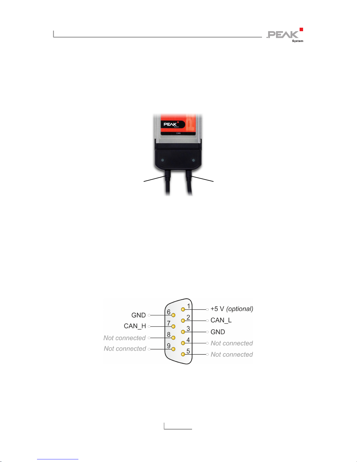
3.1 Connection over D-Sub Connector
A High-speed CAN bus (ISO 11898-2) is connected to the 9-pin
D-Sub connector. The pin assignment for CAN corresponds to the
specification CiA® 303-1.
Figure 2: Pin assignment High-speed CAN
(view onto a male D-Sub connector at the PCAN-PC Card)
CAN 1
CAN 2

PCAN-PC Card – User Manual
9
With pin 1 devices with low power consumption (e.g. bus
converters) can be directly supplied via the CAN connector. At
delivery this pin is deactivated. You can find a detailed description
in the following section 3.2.
Tip: You can connect a CAN bus with a different transmission
standard via a bus converter. PEAK-System offers different bus
converter modules (e.g. PCAN-TJA1054 for a Low-speed CAN
bus according to ISO 11898-3).
3.2 Voltage Supply of External Devices
External devices with low power consumption (e.g. bus converters)
can be directly supplied via the CAN connector (with the Dual
Channel model simultaneously for both CAN connectors). With the
provided Windows software PCAN-View, the 5-Volt supply can be
activated onto pin 1 of the D-Sub CAN connector.
The galvanically decoupled models of the card have an
interconnected DC/DC converter. Therefore, the current output is
limited to 50 mA.
You find further information about the use of this option in PCANView in section 5.1.3.
3.3 Cabling
3.3.1 Termination
A High-speed CAN bus (ISO 11898-2) must be terminated on both
ends with 120 Ohms. Otherwise, there are interfering signal
reflections and the transceivers of the connected CAN nodes (CAN
interface, control device) will not work.
 Loading...