

Peak IOM57, PK-IOM5711, PK-IOM5731 Installation Instructions Manual
*2410143985C*
24-10143-985, Rev. C
(barcode for factory use only)
PEAK® IOM57 Input/Output Modules
Installation Instructions
PK-IOM5711, PK-IOM5731
Application
The PEAK IOM57 field controllers belong to the PEAK Controller family. Input/Output Module (IOM) controllers
expand the number of points that are connected to an OEM SMART Equipment controller (PEAK) to monitor and
control a wide variety of HVAC/R equipment.
PEAK IOM57 field controllers operate on an RS-485 BACnet® MS/TP bus as BACnet Application Specific
Controllers (B-ASCs) and integrate into Johnson Controls® and third-party BACnet systems.
North American Emissions Compliance
United States
This equipment has been tested and found to comply with the limits for a Class A digital device pursuant to
Part 15 of the FCC Rules. These limits are designed to provide reasonable protection against harmful
interference when this equipment is operated in a commercial environment. This equipment generates, uses,
and can radiate radio frequency energy and, if not installed and used in accordance with the instruction manual,
may cause harmful interference to radio communications. Operation of this equipment in a residential area may
cause harmful interference, in which case users will be required to correct the interference at their own expense.
Part No. 24-10143-985, Rev. C
Issued June 2018
Canada
This Class (A) digital apparatus meets all the requirements of the Canadian Interference-Causing Equipment
Regulations.
Cet appareil numérique de la Classe (A) respecte toutes les exigences du Règlement sur le matériel brouilleur
du Canada.
Installation
Observe the following guidelines when you install a field controller:
• Transport the controller in the original container to minimize vibration and shock damage.
• Verify that all parts shipped with the controller.
• Do not drop the controller or subject it to physical shock.
Parts included
• One controller with removable terminal blocks. Power, sensor actuator (SA), and field controller (FC) bus are
re
movable.
• One installation instructions sheet.
Materials and special tools needed
• Three fasteners appropriate for the mounting surface (M4 screws or #8 screws).
• One 20 cm (8 in.) or longer piece of 35 mm DIN rail and appropriate hardware for DIN rail mount (only).
• Small straight-blade screwdriver to secure wires in the terminal blocks.
PEAK® IOM57 Input/Output Modules Installation Instructions
1
Mounting
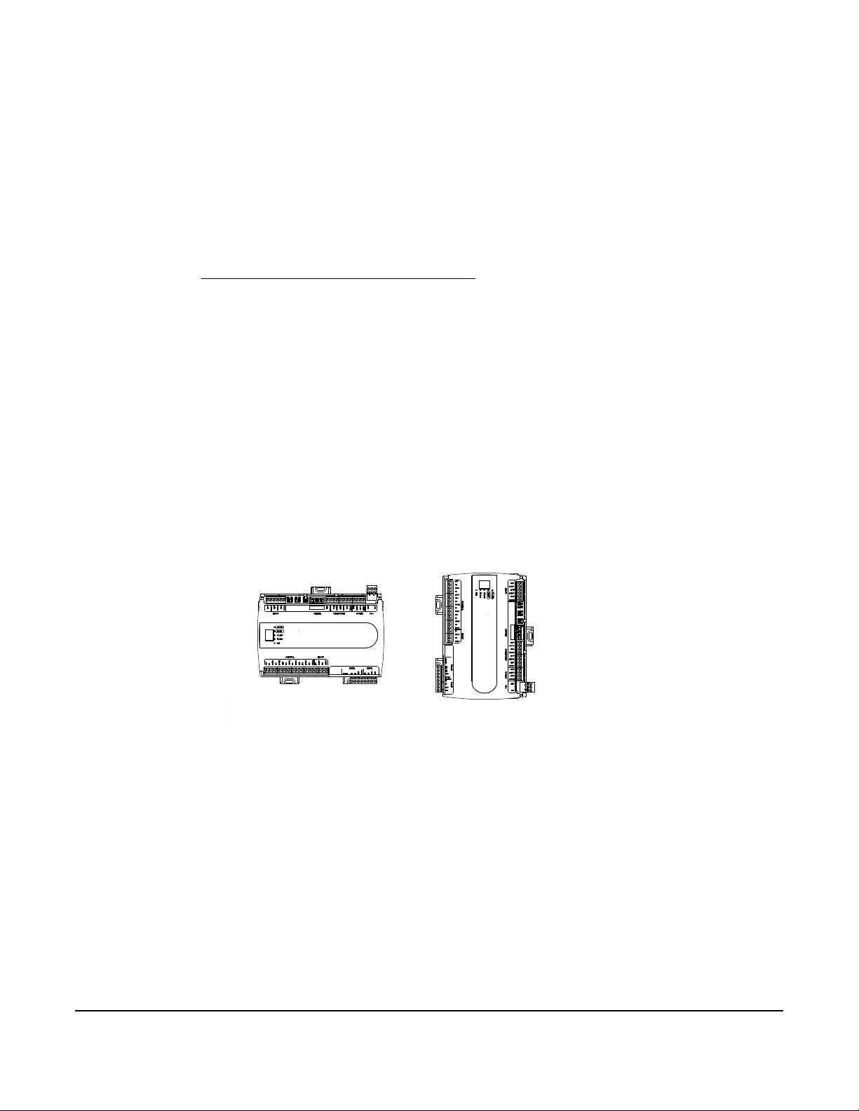
Figure 1: Controller mounting positions
V
FIG:fec_mounting_positions
Observe these guidelines when you mount a field controller:
• Ensure the mounting surface can support the controller, DIN rail, and any user-supplied enclosure.
• Mount the controller horizontally on a 35 mm DIN rail whenever possible.
• Mount the controller in the proper mounting position Figure 1.
• Mount the controller on hard, even surfaces whenever possible in wall-mount applications.
• Use shims or washers to mount the controller securely and evenly on the mounting surface.
• Mount the controller in an area that is free of corrosive vapors, and observe the ambient conditions
requirements in PEAK IOM57 Series technical specifications
• Provide for sufficient space around the controller for cable and wire connections to ensure easy cover removal
and good ventilation through the controller (50 mm [2 in.] minimum on the top, bottom, and front of the
controller).
• Do not mount the controller on surfaces prone to vibrations, such as duct work.
• Do not mount the controller in areas where electromagnetic emissions from other devices or wiring can
interfere with controller communication.
Observe these additional guidelines when you mount a field controller in a panel or enclosure:
• Mount the controller so that the enclosure walls do not obstruct cover removal or ventilation through the
controller.
.
• Mount the controller so that the power transformer and other devices do not radiate excessive heat to the
controller.
• Do not install the controller in an airtight enclosure.
Horizontal Mount Position
Preferred for Wall Mounting
Required for DIN Rail Mounting
ertical Mount Position
Acceptable for Wall Mounting
DIN rail mount applications
Mounting the controller horizontal on 35 mm DIN rail is the preferred mounting method.
To mount a field controller on a 35 mm DIN rail:
1. Securely mount a 20 cm (8 in.) or longer section of 35 mm DIN rail and mount the controller in the horizontal
and centered position, as shown in Figure 1.
2. Pull the bottom mounting clip outward from the controller to the extended position, as shown in Figure 2.
3. Hang the controller on the DIN rail through the hooks at the top of the DIN rail channel on the back of the
controller, and position the controller against the DIN rail. See Figure 2 for details.
PEAK® IOM57 Input/Output Modules Installation Instructions
2
4. To secure the controller on the DIN rail, push the bottom mounting clip in and up.
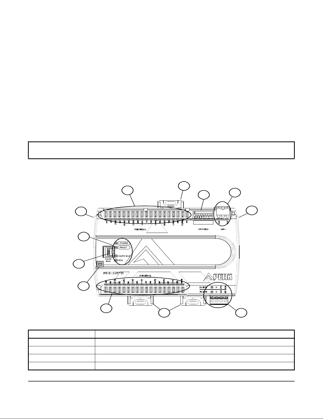
Figure 2: PEAK IOM5711 physical features
1
2
2
3
4
4
5
8
9
6
6
7
To remove the controller from the DIN rail, pull the bottom mounting clip out to the extended position and
carefully lift the controller off the DIN rail.
Wall mount applications
To mount a field controller directly on a wall or other flat vertical surface, complete the following steps:
1. Pull the bottom mounting clip outward and ensure that it is locked in the extended position, as shown in
Figure 2.
2. Position the controller in the proper mounting position shown in Figure 2 and mark the mounting hole locations
on the wall or surface. Alternatively, hold the controller up to the wall or surface in the proper mounting position
and mark the hole locations through the mounting clips.
3. Drill holes in the wall or surface at the marked locations, and insert appropriate wall anchors in the holes if
necessary.
4. Hold the controller in place, and insert the screws through the mounting clips and into the holes or wall
anchors. Carefully tighten all of the screws.
IMPORTANT: Do not overtighten the mounting screws. Overtightening the screws may damage the mounting
clips.
Table 1: PEAK IOM5731 physical features (Part 1 of 2)
Callout Physical feature: description and references
1 Device address DIP switch block
2 Mounting clip
3 24 VAC, Class 2 supply power terminal block
4 Cover lift tab
PEAK® IOM57 Input/Output Modules Installation Instructions
3
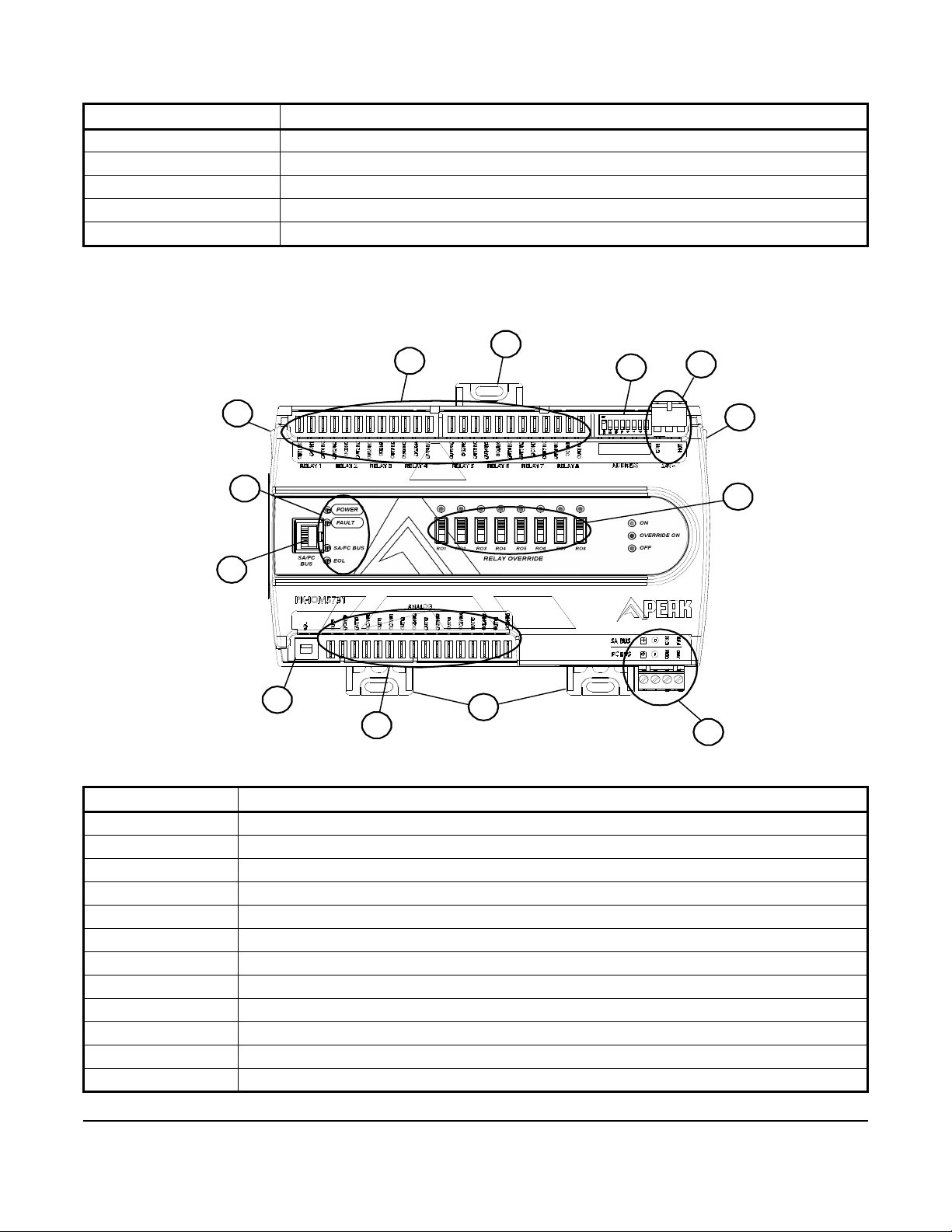
Table 1: PEAK IOM5731 physical features (Part 2 of 2)
Figure 3: IOM5731 physical features
1
2
2
3
4
4
5
8
9
7
12
11
10
Callout Physical feature: description and references
5 SA bus or FC bus
6 Universal inputs (UI) (not available on IOM5731)
7 End-of-Line (EOL) switch (located under the cover)
8 SA bus or FC bus port (RJ-12 6-pin modular jack)
9 LED status indicators
Table 2: IOM5711 physical features
Callout Physical feature: Description and references
1 Device address DIP Switch Block
2 Mounting clip
3 24 VAC, Class 2 supply power terminal block
4 Cover lift tab
5 SA bus or FC bus
6 Universal inputs (UI) (not available on IOM5731)
7 End-of-Line (EOL) switch
8 SA bus or FC bus port (RJ-12 6-pin modular jack)
9 LED status indicators
10 Analog outputs (AO) (not available on IOM5711)
11 Relay override switches (not available on IOM5711)
12 Relay outputs (not available on IOM5711)
PEAK® IOM57 Input/Output Modules Installation Instructions
4
Wiring
Risk of Electric Shock.
Disconnect or isolate all power supplies before making electrical connections. More than one disconnection or
isolation may be required to completely de-energize equipment. Contact with components carrying hazardous
voltage can cause electric shock and may result in severe personal injury or death.
Risque de décharge électrique.
Débrancher ou isoler toute alimentation avant de réaliser un branchement électrique. Plusieurs isolations et
débranchements sont peut-être nécessaires pour -couper entièrement l'alimentation de l'équipement. Tout contact
avec des composants conducteurs de tensions dangereuses risque d'entraîner une décharge électrique et de
provoquer des blessures graves, voire mortelles.
Risk of Property Damage.
Do not apply power to the system before checking all wiring connections. Short circuited or improperly connected
wires may result in permanent damage to the equipment.
Risque de dégâts matériels.
Ne pas mettre le système sous tension avant d'avoir vérifié tous les raccords de câblage. Des fils formant un
court-circuit ou connectés de façon incorrecte risquent d'endommager irrémédiablement l'équipement.
IMPORTANT: Do not exceed the controller electrical ratings. Exceeding controller electrical ratings can result in
permanent damage to the controller and void any warranty.
IMPORTANT: Use copper conductors only. Make all wiring in accordance with local, national, and regional
regulations.
IMPORTANT: Electrostatic discharge can damage controller components. Use proper electrostatic discharge
precautions during installation, setup, and servicing to avoid damaging the controller.
For detailed information on configuring and wiring an MS/TP bus, FC bus, and SA bus, refer to the MS/TP
Communications Bus Technical Bulletin (LIT-12011034).
Terminal blocks and bus ports
See Figure 2 for terminal block and bus port locations on the controller. Observe the following guidelines when
wiring a controller.
Input and output terminal blocks
Most of the input terminal blocks are mounted on the bottom of the controller and the output terminal blocks are
mounted on the top of the controller. See Table 4 for more information about I/O terminal functions, requirements,
and ratings.
PEAK® IOM57 Input/Output Modules Installation Instructions
5
SA/FC bus terminal block
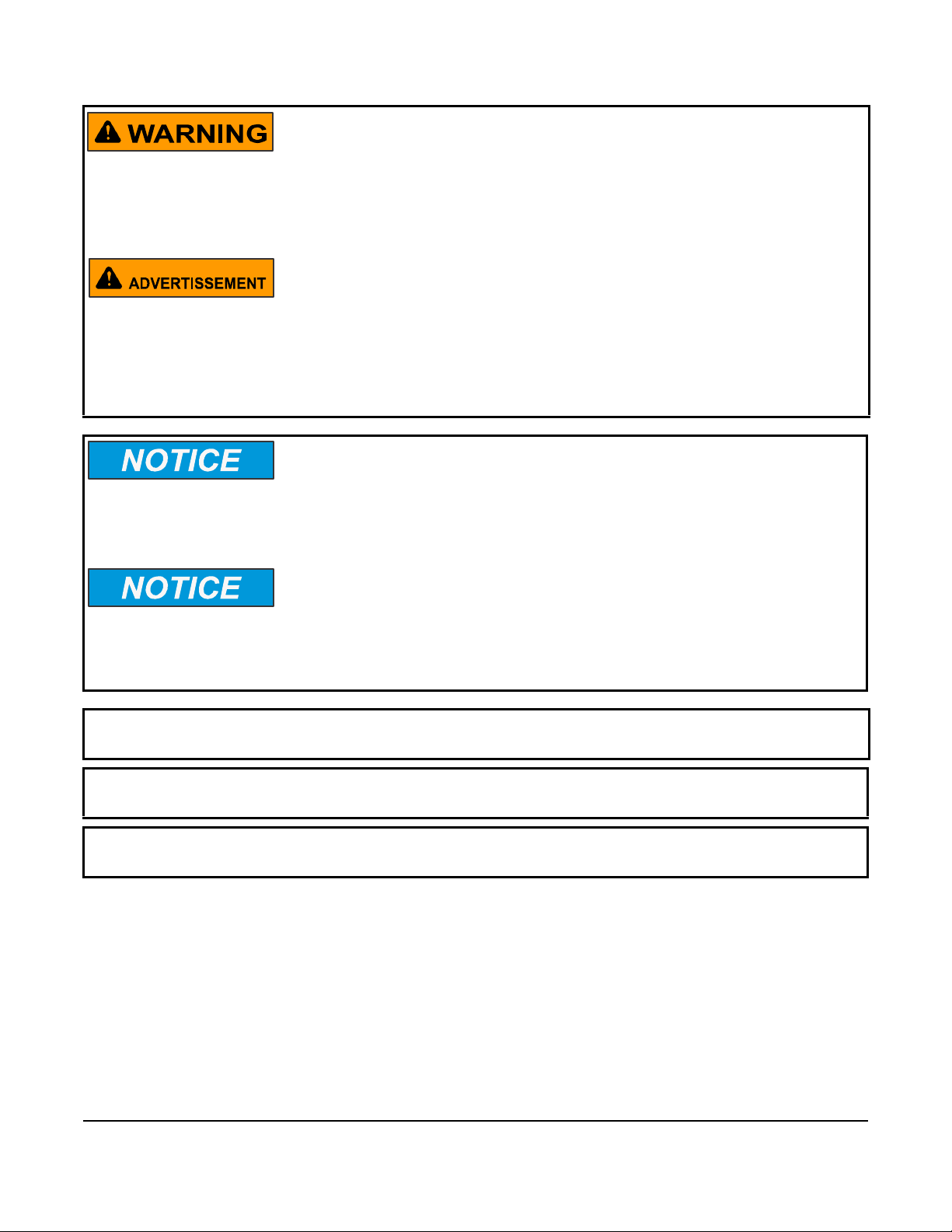
Figure 4: FC bus terminal block wiring
Stranded 3-Wire Twisted Shielded Cable
Isolated Shield
Connection
Terminal
+
_
COM
SHLD
To N ex t
Device on
the FC Bus
Segment
FC Bus
Terminal
Block Plugs
FIG: fc _bus_terms
+
_
COM
SHLD
Terminating Device
on FC Bus Segment
To Nex t
Device on
the FC Bus
Segment
Daisy Chained Device
on FC Bus Segment
Figure 5: SA bus terminal block wiring
Stranded, 4-Wire (2 Twisted Pair) Shielded Cable
(One twisted pair is the and leads.
+ -
The second pair is COM and SA PWR.)
Cable Shield
Connection
To N ex t
Device on
the SA Bus
FIG:sa_b us_terms
SA Bus
Terminal
Block Plugs
Terminating Device
on SA Bus
Daisy Chained Device
on SA Bus
To N ex t
Device on
the SA Bus
+
COM
SA PWR
+
COM
SA PWR
You can connect an IOM to an SA bus or an FC bus, but not to both buses simultaneously. The SA/FC bus terminal
block is a removable, 4-terminal plug that fits into a board-mounted jack.
When you connect the IOM to an FC bus, wire the bus terminal block plugs on the controller and the other
controllers in a daisy-chain configuration using 3-wire twisted, shielded cable as shown in Figure 4. See Table 6 for
more information.
When you connect the IOM to an SA bus, wire the bus terminal block plugs on the controller and other SA bus
devices in a daisy-chain configuration using 4-wire twisted, shielded cable as shown in Figure 5. See Table 4 for
more information.
Note: The SA PWR/SHLD terminal does not supply 15 VDC. The SA PWR/SHLD terminal is isolated and you can
use the terminal to connect (daisy chain) the 15 VDC power leads on the SA bus (Figure 5) or the cable shields on
the FC bus (Figure 4). The SA bus supervisor advanced application field equipment controller (FAC), field
equipment controller (FEC), or VAV modular assembly (VMA) supplies 15 VDC to devices on the SA bus that
require power.
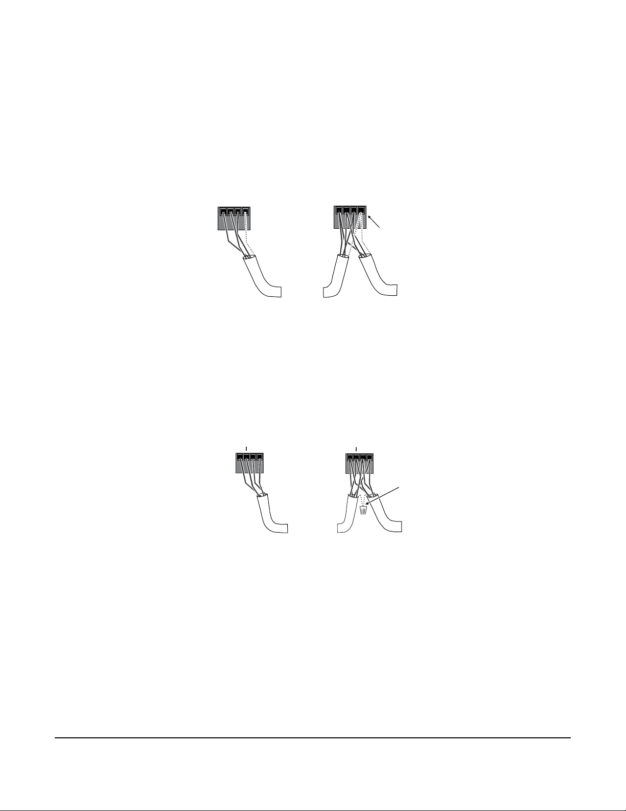
SA/FC bus port
The SA/FC bus port on the front of the controller is an RJ-12, 6-position modular jack that provides a connection for
devices on the SA bus, a Wireless Commissioning Converter, ZigBee® wireless dongle, or a ZFR1811 Wireless
Router, depending on which bus the IOM is operating on.
PEAK® IOM57 Input/Output Modules Installation Instructions
6
The SA/FC bus port connects internally to the SA/FC bus terminal block. See Figure 6 for more information. The
Figure 6: Pin number assignments for sensor,
SA bus, and FC bus ports on controllers
SA or FC Bus
-
Bus and Power Common
Power
(15 VDC)
(RJ-12 Modular Jack)
Bus and Power Common
FIG:fec_rj1 2_pinout
2
3
4
5
6
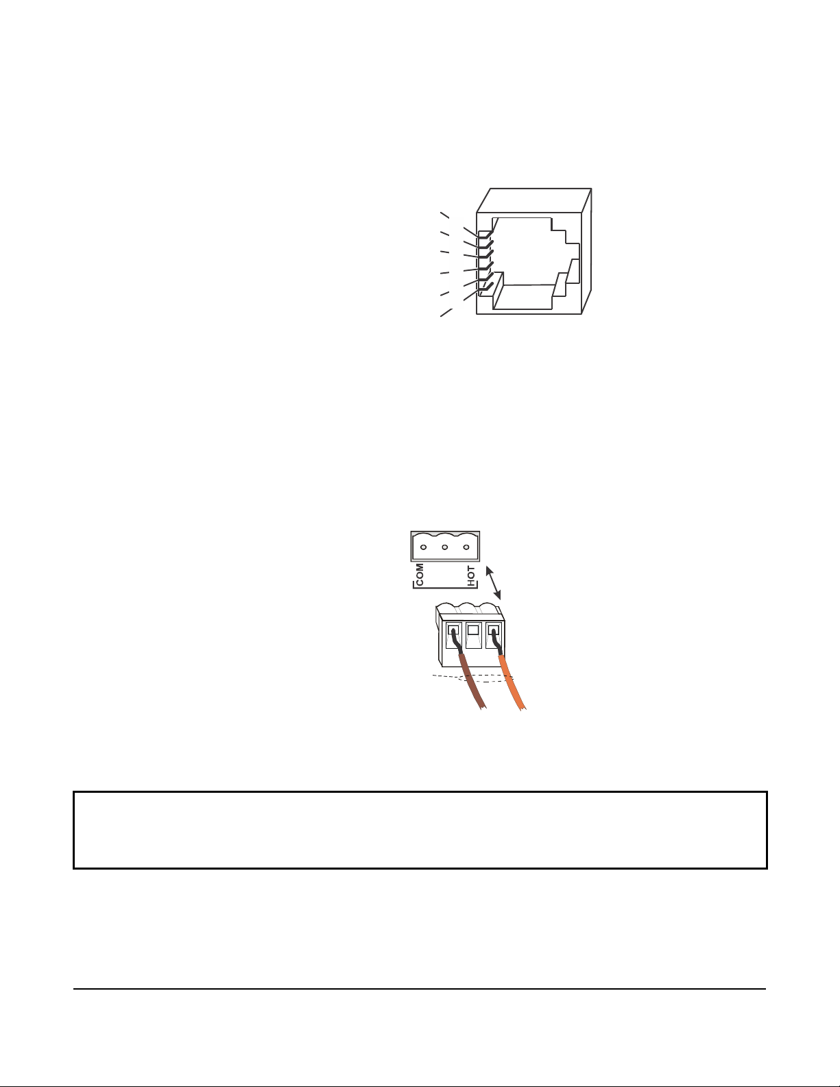
Figure 7: 24 VAC supply power terminal
block wiring
Supply Power
Ter minal Bl oc k
Jack
Supply Power
Terminal Block
Plug
Wire s from
Johnson Controls
24 VAC, Class 2
Power Transformer
Brown Wire
(COM)
Orange Wire
(24 VAC)
FIG:fec_power _port
24V~
COM
HOT
Disconnect supply power to controller by unplugging
Supply Power Plug from Supply Power Jack.
SA/FC bus port pin assignment is also shown in Figure 6.
Sensor, SA Bus, or FC Bus Port
Power
(15 VDC)
SA or FC Bus +
1
Supply power terminal block
The 24 VAC supply power terminal block is a gray, removable, 3-terminal plug that fits into a board-mounted jack
on the upper-right of the controller.
Wire the 24 VAC supply power wires from the transformer to the HOT and COM terminals on the terminal plug as
shown in Figure 7. The middle terminal on the supply power terminal block is not used. See Table 6 for more
information about the supply terminal block.
Note: The supply power wire colors may differ on transformers from other manufacturers. Refer to the transformer
manufacturer’s instructions and project installation drawings for wiring details.
IMPORTANT: Connect 24 VAC supply power to the controller and all other network devices so that transformer
phasing is uniform across the network devices. Powering network devices with uniform 24 VAC supply power
phasing reduces noise, interference, and ground loop problems. The controller does not require an earth ground
connection.
PEAK® IOM57 Input/Output Modules Installation Instructions
7
 Loading...