

Peak Genius 3023 Installation Manual
Fountain Crescent
Inchinna Business Park
Inchinnan, PA4 9RE
Scotland, UK
T: +44 (0)141 812 8100
F: +44 (0)141 812 8200
W: www.peakscientific.com
E: info@peakscientific.com
Part No. IG-Genius 3023
Rev. 01
Page Page 1 of 9
x 1
x 2
Installation Guide – Genius 3023 Generator
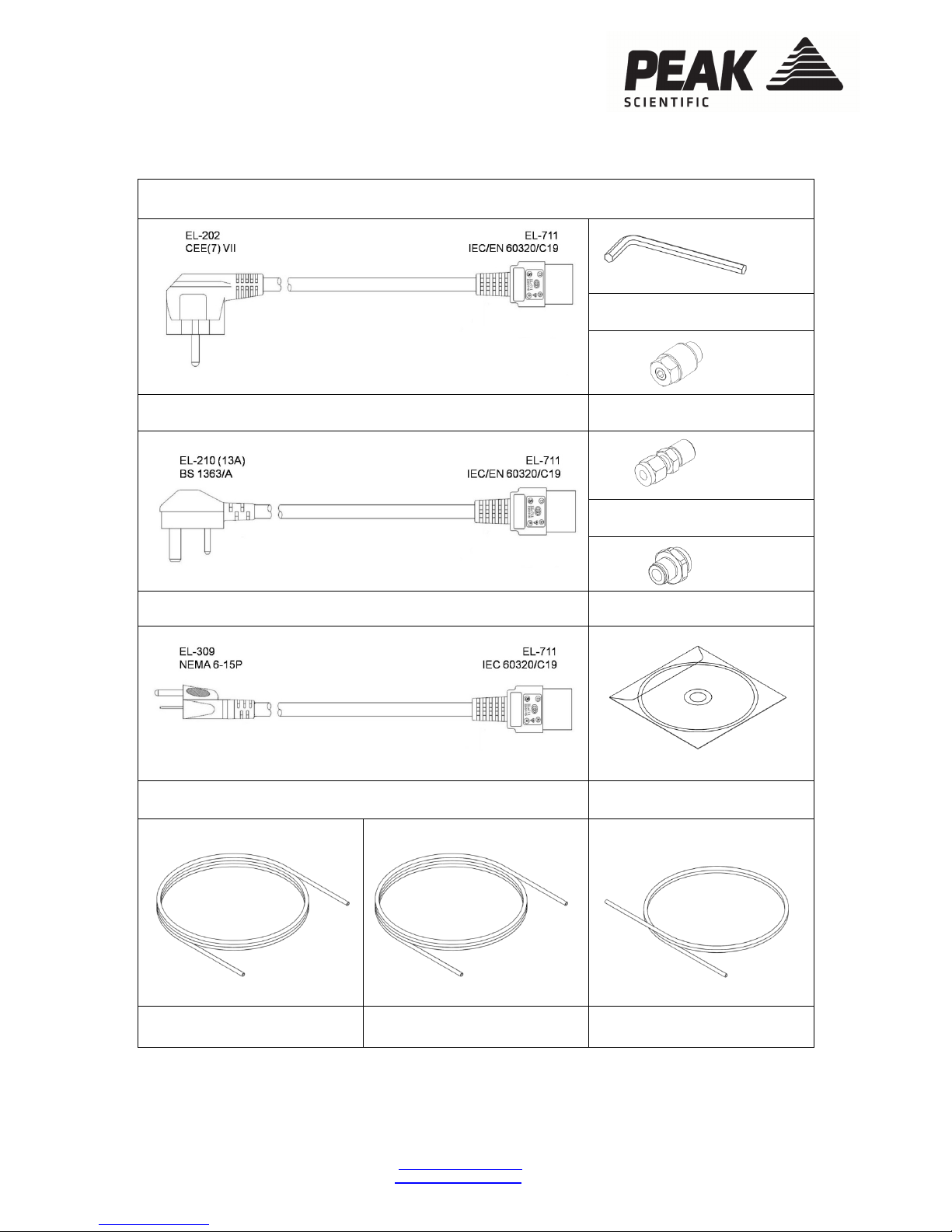
FITTINGS KIT
8mm Hex Key
Mains Cable – Euro Silencer Fitting
¼” Compression Fitting
Mains Cable – UK 6mm Push-fit Fitting
Mains Cable - US CD containing User Manual
¼” Teflon Tube 6mm Teflon Tube 6mm Nylon Tube
x 1
x 3
x 6m
x 6m
x 4m
x 1
x 2
x 1
x 1
Fountain Crescent
Inchinna Business Park
Inchinnan, PA4 9RE
Scotland, UK
T: +44 (0)141 812 8100
F: +44 (0)141 812 8200
W: www.peakscientific.com
E: info@peakscientific.com
Part No. IG-Genius 3023
Rev. 01
Page Page 2 of 9
INSTALLATION
1.
2.
3.
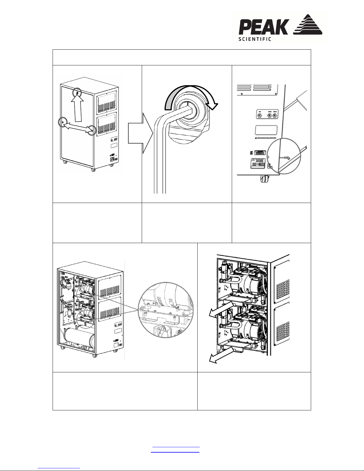
Unpack the generator from
the shipping crate and place
on a flat surface. To remove
the transit brackets, firstly
remove the RH side panel.
Using the Hex-Key provided in
the fittings kit, turn the locks
90
o
to the right.
An earth lead is connected
to the inside of the panel.
This can be disconnected
by pulling it off the spade
connector on the door.
4.
5.
With the RH side panel removed you now have
access to the RH transit brackets. These are
located under both of the RH compressors and are
painted red. To remove the transit brackets
remove the 4 screws on each bracket as indicated.
Once these screws have been
removed the transit brackets can be
pulled out as shown.
Fountain Crescent
Inchinna Business Park
Inchinnan, PA4 9RE
Scotland, UK
T: +44 (0)141 812 8100
F: +44 (0)141 812 8200
W: www.peakscientific.com
E: info@peakscientific.com
Part No. IG-Genius 3023
Rev. 01
Page Page 3 of 9
6.
7.
Remove the LH side panel as before,
taking care to disconnect the earth lead
located on the inside of the door panel.
Repeat steps 4 and 5 to remove the LH transit
brackets located under both of the LH
compressors. These will pull out in the same
way.
**NOTE**
Do not discard the transit brackets or screws as these
will be needed again if the
unit is to be transported from its current location.
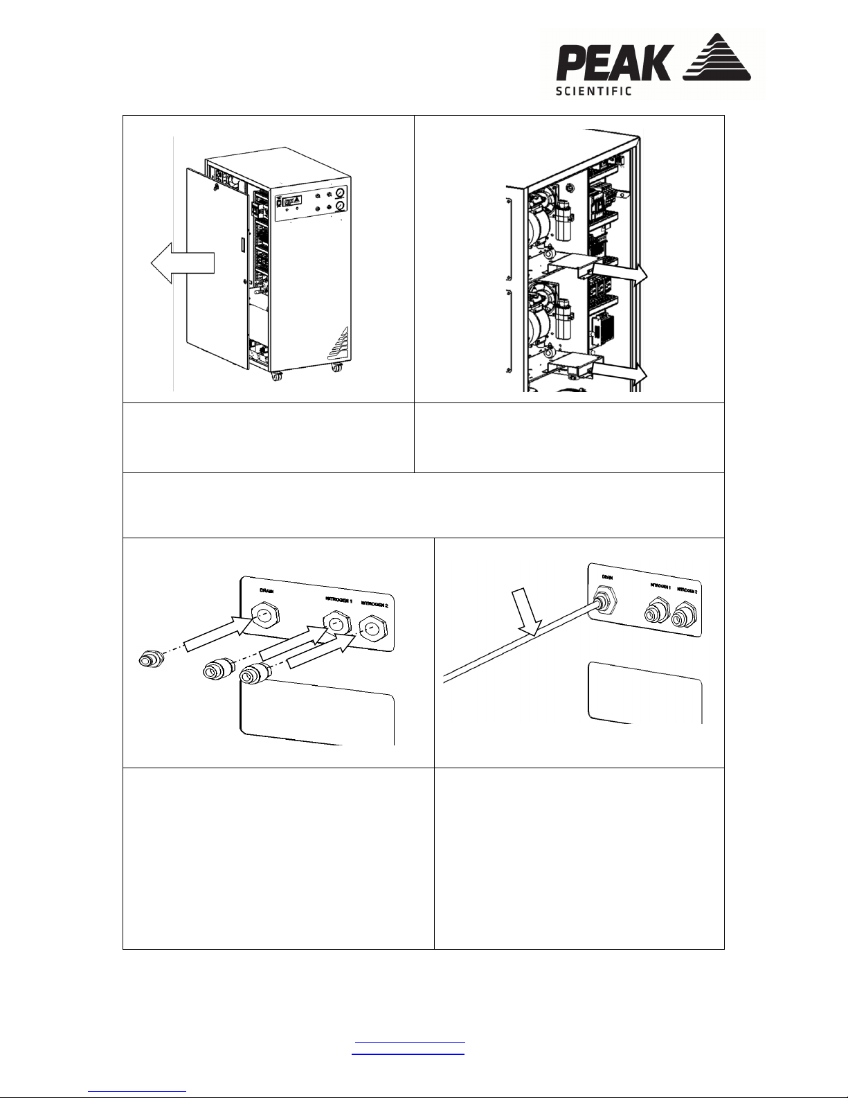
8.
9.
From the fittings kit, select one of the 6mm
push-fit fittings and connect it to the port
marked ‘DRAIN’ on the rear of the unit using a
16mm or 5/8” spanner.
Fit the silencers fitting into the ports marked
‘NITROGEN’. These only needs to be hand
tight as these are a temporary fitting for the
purge run and will be removed again prior to
connecting to the instrument.
Connect the 4m Nylon tube to the drain
line, ensure the tube is pushed fully in and
gripped securely by the fitting.
Fit the other end of the drain line to a
suitable drain connection or container. The
container must NOT have an airtight seal
as water and air will be expelled
periodically under a slight pressure.
2m Nylon to Drain
 Loading...