

Peak Genius 1023, Genius 1022, Genius NM32LA, Genius NM32LA-A Installation Manual
Genius 1022, 1023 & NM32LA (All Models)
Installation Guide
Copyright © Peak Scientific Instruments Ltd 2017 — Genius1022-1023-NM32LA Installation Guide Rev 2 PN IG-0001 RSID 1390 EN —10/11/2017

Page 2
Change History
Rev Comment Name Date
How to use this Installation Guide
This document is intended to be used only as a Quick Start Guide, to facilitate safe and
correct installation and initial configuration of your Peak Scientific gas generator.
For more extensive user operation directions, we recommend you download the User
Manual from the website.
Please visit www.peakscientific.com/downloads to
download the full User Manual for your gas generator.
Thank you for selecting Peak Scientific to meet your laboratory gas generation needs,
and should you require any further assistance or support please do not hesitate to
contact Peak Scientific or Peak Partner from which you purchased your generator.
Page 3
Safety Notices
Peak Scientific Instruments cannot anticipate every possible circumstance which may
represent a potential hazard. The warnings detailed within this document detail the
most known potential hazards, but by definition cannot be all inclusive. If the user
employs an operating procedure, item of equipment or a method of working which
is not specifically recommended by Peak Scientific, the user must ensure that the
equipment will not be damaged or become hazardous to persons or property.
Symbols
This document uses the following symbols to highlight specific areas important to the
safe and proper use of the Generator
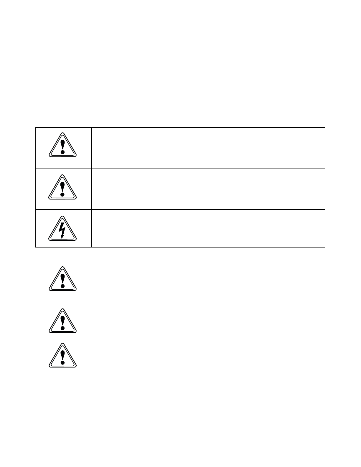
A WARNING notice denotes a hazard. It calls attention to an operating procedure,
process or similar, which if not correctly performed or adhered to, could cause
personal injury or in the worst case death. Do not proceed beyond a WARNING
notice until the indicated conditions are fully understood or met.
A CAUTION notice denotes a hazard. It calls attention to an operating procedure,
process or similar, which if not correctly performed or adhered to, could cause
damage to the Generator or the Application. Do not proceed beyond a CAUTION
notice until the indicated conditions are fully understood or met.
Caution, risk of electric shock. Ensure power to the Generator has been removed
before proceeding.
Safety Notice to Users
These instructions must be read thoroughly and understood before
installation and operation of your Peak Generator. Use of the generator
in a manner not specified by Peak Scientific MAY impair the SAFETY
provided by the equipment.
When handling, operating or carrying out any maintenance, personnel
must employ safe engineering practices and observe all relevant local
health and safety requirements and regulations. The attention of UK
users is drawn to the Health and Safety at Work Act 1974, and the
Institute of Electrical Engineers regulations.
If the equipment is used in a manner not specified by the manufacturer,
the protection provided by the equipment may be impaired.
WARNING
WARNING
WARNING
WARNING
CAUTION
Page 3
Page 4
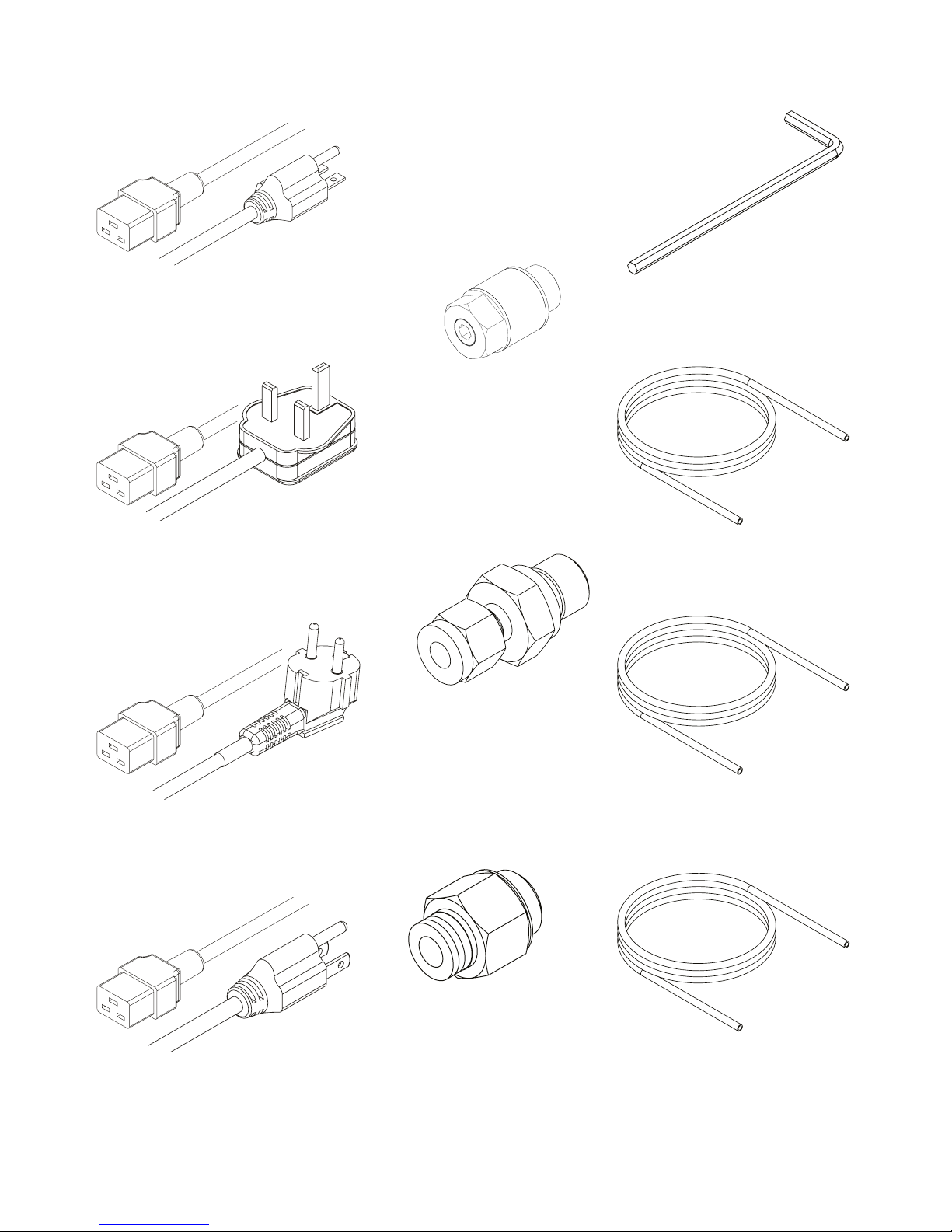
Fittings Kit
x1*
UK Mains Cable C19 04-1025
x1*
US Mains Cable 230V C19 6-15 04-1024
x1*
EU Mains Cable C19 04-1026
x3m
6mm Teflon White 00-1302
x3m
1/4” Teflon Tubing 00-1266
x3m
6mm OD x 4mm ID PE 00-1282
x1
8mm Hex Key 00-0007
x1
Flow Control SIlencer 02-1096
x1
1/4” Compression Fitting
02-4421
x2
1/4” - 6mm Push Fit Fitting
02-4600
x1**
US Mains Cable 110V C19 5-15 04-1035
* Genius 1022, 1023 and NM32LA Only
** NM32LA 110V Only
Page 5
Unpack the generator from the shipping crate and position on a flat surface, in
desired area.
1.
2.
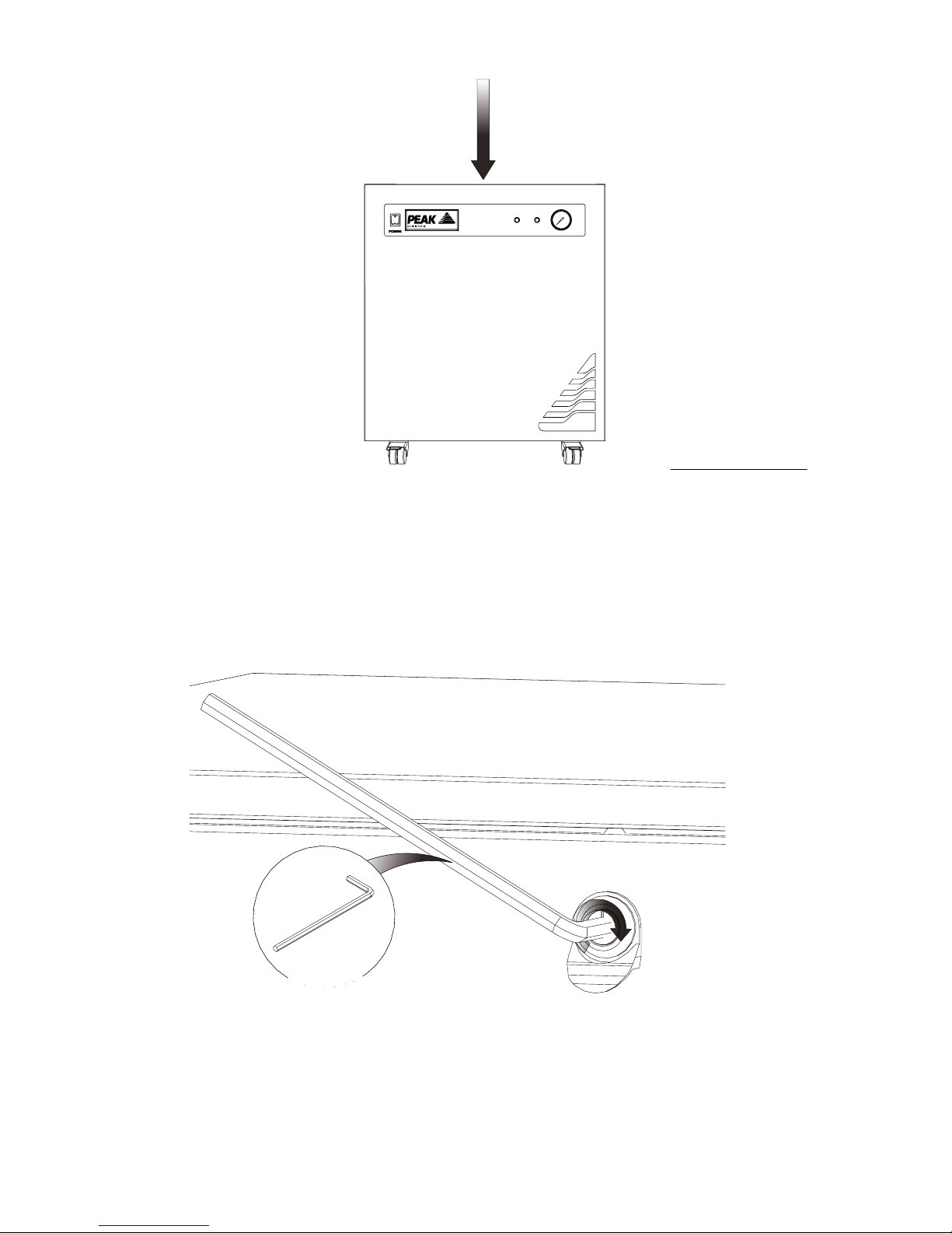
First remove the compressor transit brackets.
These can be accessed by removing the generator side panels. Starting with the left
hand side panel, use the 8mm Hex Key 00-0007, and turn the lock 90° to the right.
0°
0°
00-0007
Page 6
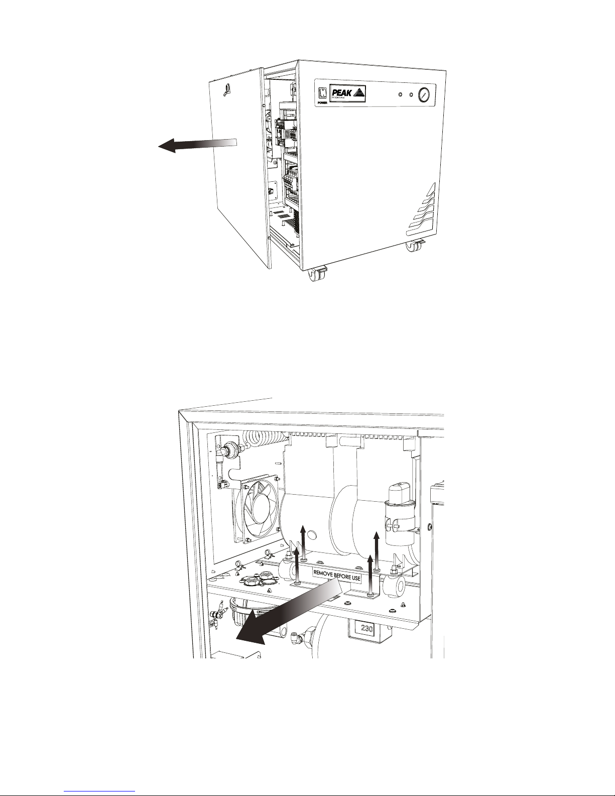
3.
Once unlocked remove the left hand side panel, ensuring you disconnect the earth
lead located in the lower middle of the panel.
4.
The transit bracket is located below the compressor and has a sticker on it stating
‘Remove before use’. To remove the transit bracket, remove the four screws as
indicated, then slide the bracket out from underneath the compressor. Please retain
the bracket and screws for future transportation.
 Loading...