

Peak DLA200 Installation And Operating Handbook

Handbook Issue 1.00, 20
th
October 2009
1997
EN 55022 CLASS B
EN 50082-1
EN 60950
PEAK COMMUNICATIONS Ltd.
Kirklees House, 22 West Park Street
Brighouse, West Yorkshire
HD6 1DU, England
Phone 01484 714200
Fax 01484 723666
IMPORTANT NOTE: THE INFORMATION AND SPECIFICATIONS
CONTAINED IN THIS DOCUMENT SUPERCEDE ALL PREVIOUSLY
PUBLISHED INFORMATION CONCERNING THIS PRODUCT
PEAK COMMUNICATIONS Ltd maintains a continuing programme of product
improvement and therefore reserves the right to change specifications without notice
Installation and Operating handbook
DLA200 Dual Line Amplifier Unit

Issue 1.00 DLA200 Dual Line Amplifier Units Page 2
INTRODUCTION
The DLA200 units are able to power 2 MLA Amplifier units.
The DLA200 units are housed in 19 inch 1'U' high chassis, suitable for rack mounting. They are 400 mm
deep and may be fitted with rack slides if required.
EMC AND SAFETY
EMC
The DLA200 units have been designed to comply with the following standards;
Emissions : EN 55022 Class B; Limits and methods of measurement of radio interference
characteristics of Information Technology Equipment.
Immunity : EN 50082 Part 1; Generic immunity standard, part 1: Domestic, commercial and light
industrial environment.
The equipment must be operated with its lid on at all times. If it is necessary to remove the lid for routine
servicing or fault finding then it is essential that the lid is fitted back correctly before normal operation.
For the Alarm and Remote Control data interfaces all 'D' type connectors must have grounding fingers on
the plug shell to guarantee continuous shielding. The back-shells must comply with the requirements of
VDE 0871 and FCC 20708, providing at least 40 dB of attenuation from 30 MHz to 1 GHz.
Connecting cables must be of the shielded
Operation of the equipment in a non standard manner will invalidate compliancy to these
standards.
Safety
To ensure safety of operator the DLA200 units have been designed to comply with the following safety
standard;
EN 60950 Safety of information technology equipment, including electrical business machines.
Before operation the user must ensure that the installation complies with the information given.
The equipment is designed to operate in a static 19 inch rack system conforming to IEC 297-2. Operation
of the equipment in transportable vehicles equipped with the means of providing a stable environment is
permissible. Operation of the equipment on board vehicles, ships or aircraft without means of
environmental conditioning will invalidate the safety compliancy; please contact the factory for further
advice. Operation of the equipment in an environment other than that stated in the specifications will also
invalidate the safety compliancy. The equipment must not be operated above 2000 metre altitude,
extremes of temperature; excessive dust, moisture or vibration; flammable gases; corrosive or explosive
atmospheres.
Installation
The equipment is classified in EN 60950 as a pluggable equipment class A for connection to the mains
supply, as such it is provided with mains inlet cords suitable for use in the country of operation. In normal
circumstances they will be of an adequate length for installation in the rack. If a mains cord proves to be

Issue 1.00 DLA200 Dual Line Amplifier Units Page 3
too short then any replacement must have a similar type fuse (if fitted) and be manufactured to similar
specification: check for HAR, BASEC or HOXXX-X ratings on the cable. The connector ends should be
marked with one of the following : BS1636A (UK free plug 13 amp); BSI, VDE, NF-USE, UL, CSA,
OVE, CEBEC, NEMKO, DEMKO, SETI, IMQ, SEV and KEMA-KEUR for the IEC 6 amp free socket.
Schuko and North American free plugs must have similar markings.
The installation of the equipment and the connection to the mains supply must be made in compliance to
local or national wiring regulations for a category II impulse over voltage installation. The positioning of
the equipment must be such that the mains supply socket outlet for the equipment should be near the
equipment and easily accessible or that there should be another suitable means of disconnection from the
mains supply.
The equipment is designed to operate from a TN type power supply system as specified in EN 60950.
This is a system that has separate earth, line and neutral conductors. The equipment is not designed to
operate with an IT power system, which has no direct connection to earth.
SPECIFICATION
DLA units are used to power the MLA series of amplifiers a brief overview of which is included below
Frequency MLA1450; 950-1450MHz
MLA1750; 950-1750MHz
MLA2150; 950-2150MHz
Connector 50Ω, SMA, female. Option 1a; N-Type, Option 1c; BNC
Return Loss Input 16dB typical, Output 18dB typical
Gain 20dB minimum
Gain flatness ±0.25dB (bandwidths <500MHz)
±0.5dB (bandwidths <800MHz)
±1dB (bandwidths <1200MHz)
Active Directivity 22dB typical
20dB minimum
RF Input power -10dBm max. (no load, no damage)
TOIP +25dBm typical
1dB Output GCP +13dBm typical
Noise Figure 7 to 9dB typ. (frequency dependent)
Issue 1.00 DLA200 Dual Line Amplifier Units Page 4
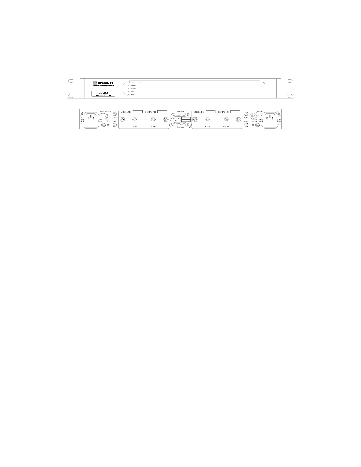
UNIT DESCRIPTION
Front panel and Rear panel
The DLA200 unit front panels have 5 indicator lights
Front panel indicators
SUMMARY ALARM GREEN both units no fault. Ext reference locked block 1 and 2
RED unit failure
BLOCK 1 GREEN Line amplifier OK and ONLINE
AMBER Line amplifier OK and OFFLINE
RED Line amplifier failure see rear panel interface connector for condition.
BLOCK 2 GREEN Line amplifier OK and ONLINE
AMBER Line amplifier OK and OFFLINE
RED Line amplifier failure see rear panel interface connector for condition.
PSU 1 GREEN mains input present
RED mains input failure
PSU 2 GREEN mains input present
RED mains input failure
Rear panel connections
INTERFACE Alarms monitoring and control of the Converter units.
Unit 2 Amplifier N/O 1
Unit 2 Amp Common 2
Unit 2 N/C 3
Unit 2 Common 4
Unit 2 power N/C 5
Unit 2 Power Common 6
Unit 2 Online 7
Ground 8
9 Unit 1 Amplifier N/O
10 Unit 1 Amp Common
11 Unit 1 N/C
12 Unit 1 Common
13 Unit 1 Power N/C
14 Unit 1 Power Common
15 Unit 1 Online
 Loading...