

Peak Atlas DCA55 User manual
GB55-10
Peak Atlas DCA
Semiconductor Component Analyser
Model DCA55
Designed and manufactured with pride in the UK
User Guide
©
Peak Electronic Design Limited 2000/2012
In the interests of development, information in this guide is subject to change without notice - E&OE

Atlas DCA User Guide November 2012 – Rev 10
Want to use it now?
We understand that you want to use your Atlas DCA right now. The
unit is ready to go and you should have little need to refer to this user
guide, but please make sure that you do at least take a look at the
notices on page 4!
Contents Page
Introduction....................................................................................3
Important Considerations...............................................................4
Analysing semiconductors .............................................................5
Diodes......................................................................................7
Diode Networks .......................................................................8
LEDs........................................................................................9
Bicolour LEDs .......................................................................10
Bipolar Junction Transistors (BJTs).......................................11
Digital Transistors..................................................................18
Enhancement Mode MOSFETs .............................................19
Depletion Mode MOSFETs ...................................................20
Junction FETs (JFETs) ..........................................................21
Thyristors (SCRs) and Triacs.................................................22
Taking care of your Atlas DCA....................................................23
Battery replacement ...............................................................23
Self Tests ...............................................................................24
Appendix A - Technical Specifications........................................25
Appendix B - Warranty Information............................................26
Appendix C - Disposal information .............................................27
Page 2

Atlas DCA User Guide November 2012 – Rev 10
Introduction
The Peak Atlas DCA is an intelligent semiconductor analyser that offers great
features together with refreshing simplicity. The Atlas DCA brings a world of
component data to your fingertips.
Summary Features:
• Automatic component type identification
Bipolar transistors
Darlington transistors
Enhancement Mode MOSFETs
Depletion Mode MOSFETs
Junction FETs
Low power sensitive Triacs
Low power sensitive Thyristors
Light Emitting Diodes
Bicolour LEDs
Diodes
Diode networks
• Automatic pinout identification, just connect any way round.
• Special feature identification such as diode protection and resistor
shunts.
• Gain measurement for bipolar transistors.
• Leakage current measurement for bipolar transistors.
• Silicon and Germanium detection for bipolar transistors.
• Gate threshold measurement for Enhancement Mode MOSFETs.
• Semiconductor forward voltage measurement for diodes, LEDs and
transistor Base-Emitter junctions.
• Automatic and manual power-off.
Page 3
Atlas DCA User Guide November 2012 – Rev 10
Important Considerations
Please observe the following guidelines:
•
This instrument must NEVER be connected to powered
equipment/components or equipment/components with any
stored energy (e.g. charged capacitors). Failure to comply
with this warning may result in personal injury, damage to
the equipment under test, damage to the Atlas DCA and
invalidation of the manufacturer’s warranty.
•
The Atlas DCA is designed to analyse semiconductors that
are not in-circuit, otherwise complex circuit effects will
result in erroneous measurements.
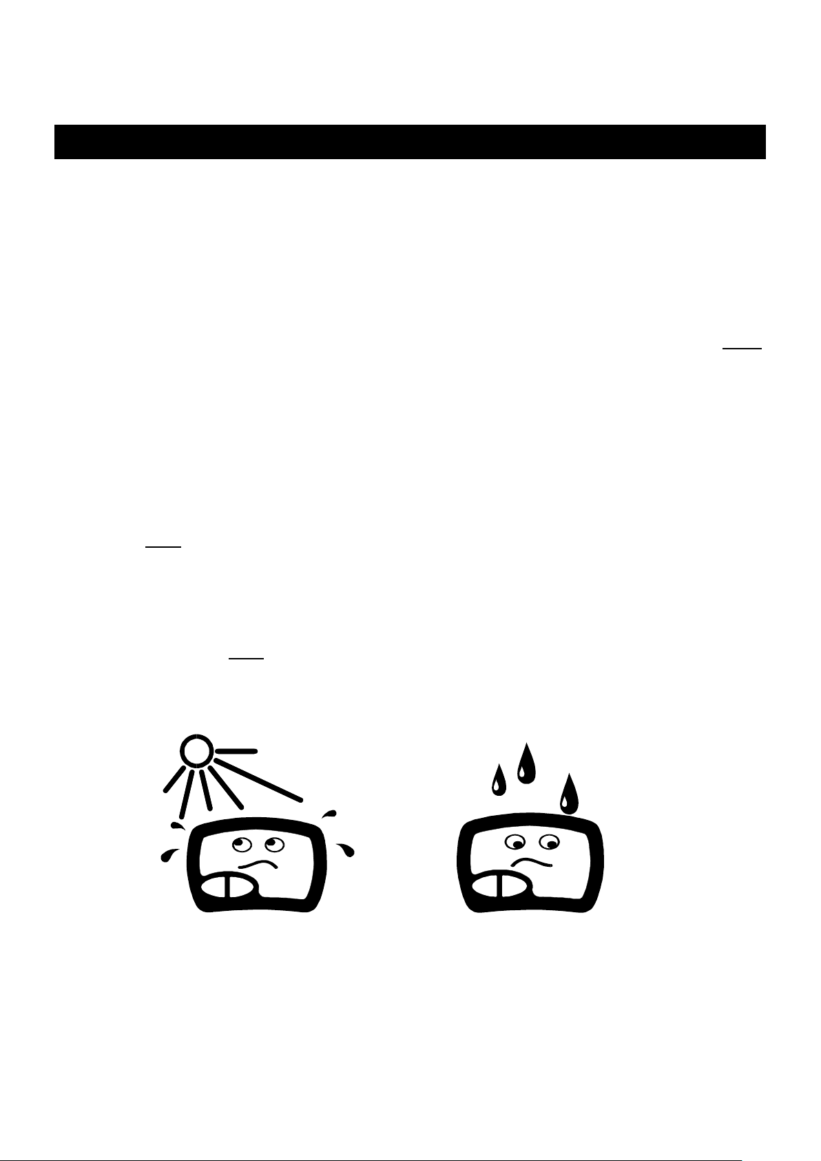
•
Avoid rough treatment or hard knocks.
•
This unit is not waterproof.
•
Only use a good quality Alkaline battery.
Page 4
Atlas DCA User Guide November 2012 – Rev 10
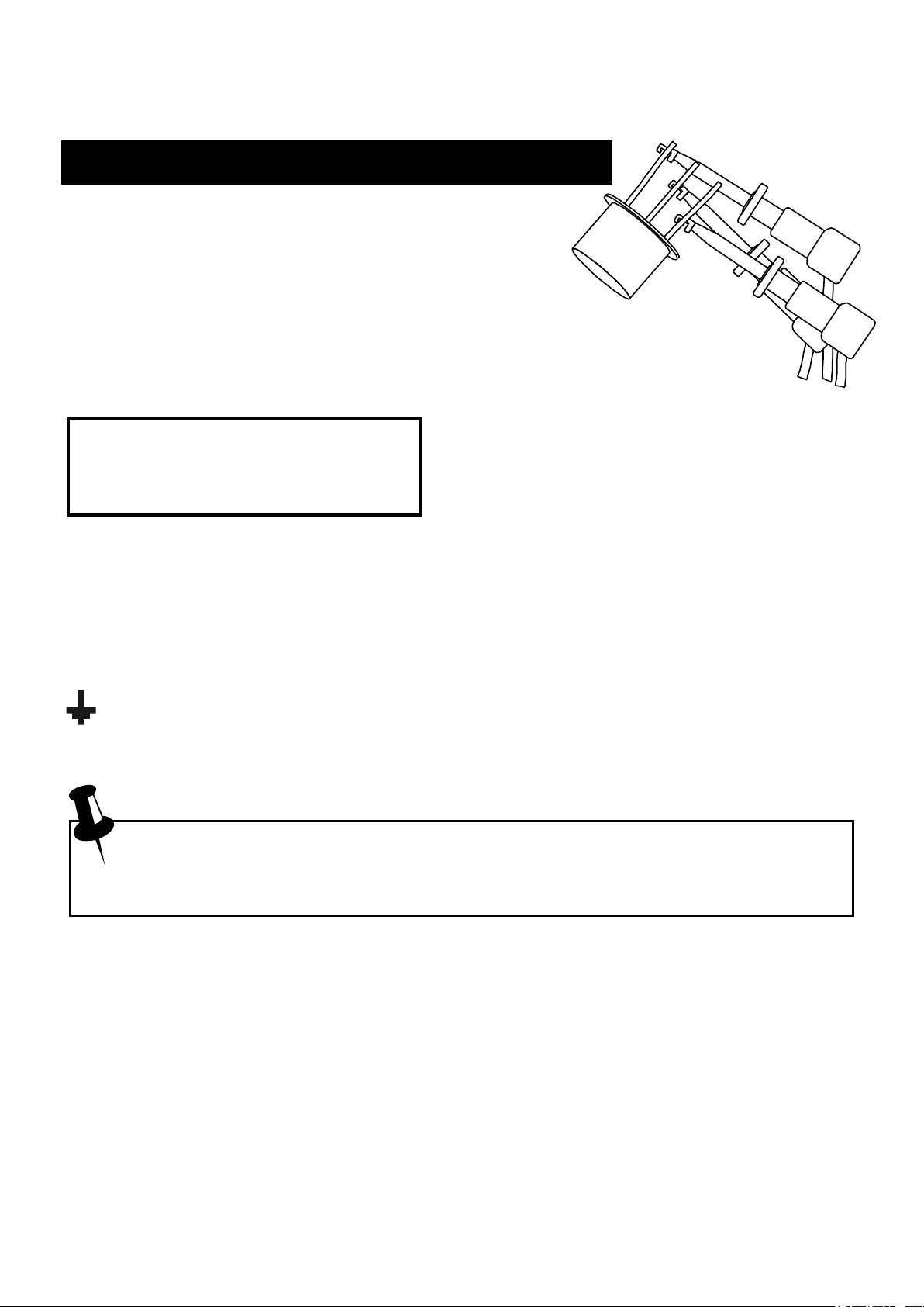
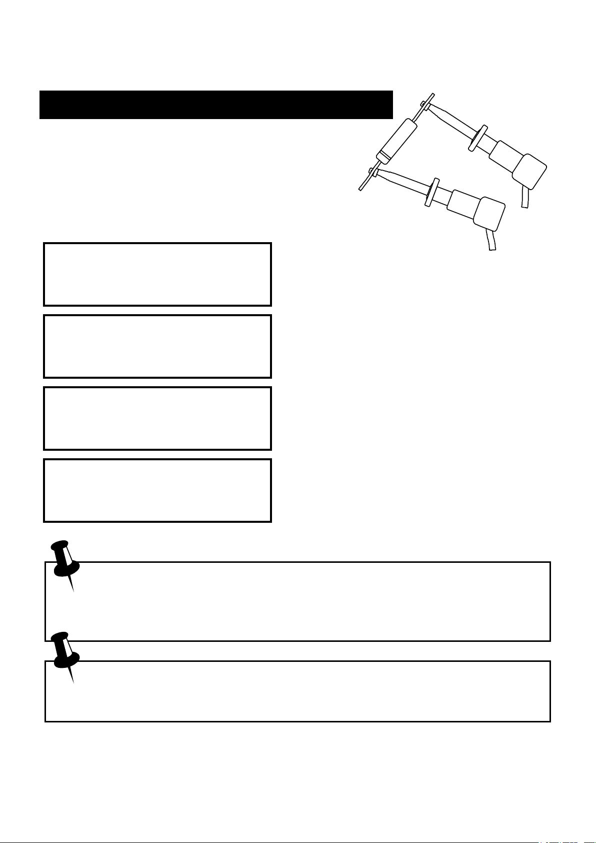
Analysing Components
The Atlas DCA is designed to analyse discrete,
unconnected, unpowered components. This
ensures that external connections don’t influence
the measured parameters. The three test probes can be
connected to the component any way round. If the component has
only two terminals, then any pair of the three test probes can be used.
The Atlas DCA will start component
Atlas DCA55 Rx.x
analysis when the on-test button is
is analysing....
Depending on the component type, analysis may take a few seconds to
complete, after which, the results of the analysis are displayed. Information is
displayed a “page” at a time, each page can be displayed by briefly pressing the
scroll-off button.
The arrow symbol on the display indicates that more pages are available
to be viewed.
Although the Atlas DCA will switch itself off if left unattended, you
can manually switch the unit off by holding down the scroll-off
button for a couple of seconds.
pressed.
Page 5
Atlas DCA User Guide November 2012 – Rev 10
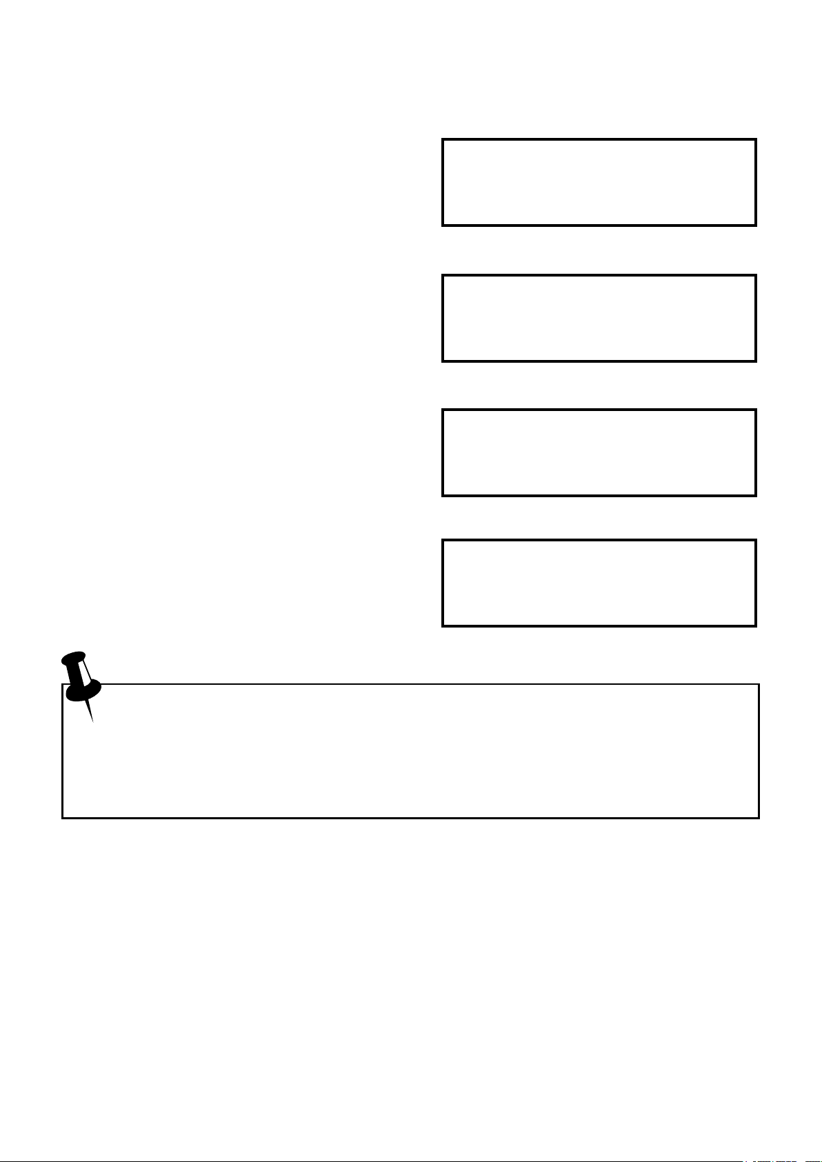
If the Atlas DCA cannot detect any
component between any of the test
probes, the following message will be
displayed:
If the component is not a supported
component type, a faulty component or
a component that is being tested incircuit, the analysis may result in the
following message being displayed:
Some components may be faulty due to
a shorted junction between a pair of the
probes. If this is the case, the following
message (or similar) will be displayed:
If all three probes are shorted (or very
No component
detected
Unknown/Faulty
component
Short circuit on
Green Blue
low resistance) then the following
message will be displayed:
It is possible that the Atlas DCA may detect one or more diode
junctions or other component type within an unknown or faulty part.
This is because many semiconductors comprise of PN (diode)
junctions. Please refer to the section on diodes and diode networks for
more information.
Short circuit on
Red Green Blue
Page 6
Atlas DCA User Guide November 2012 – Rev 10
Diodes
The Atlas DCA will analyse almost any type of
diode. Any pair of the three test clips can be
connected to the diode, any way round. If the
unit detects a single diode, the following
message will be displayed:
Diode or diode
junction(s)
RED GREEN BLUE
Anod Cath
Forward voltage
Vf=0.67V
Test current
If=4.62mA
Pressing the scroll-off
button will then display the pinout for
the diode. In this example, the Anode of
the diode is connected to the Red test
clip and the Cathode is connected to the
Green test clip, additionally, the Blue
test clip is unconnected. The forward
voltage drop is then displayed, this gives
an indication of the diode technology. In
this example, it is likely that the diode is
a silicon diode. A germanium or
Schottky diode may yield a forward
voltage of about 0.25V. The current at
which the diode was tested is also
displayed.
Note that the Atlas DCA will detect only one diode even if two diodes
are connected in series when the third test clip is not connected to the
junction between the diodes. The forward voltage drop displayed
however will be the voltage across the whole series combination.
The Atlas DCA will determine that the diode(s) under test is an LED
if the measured forward voltage drop exceeds 1.50V. Please refer to
the section on LED analysis for more information.
Page 7
Atlas DCA User Guide November 2012 – Rev 10
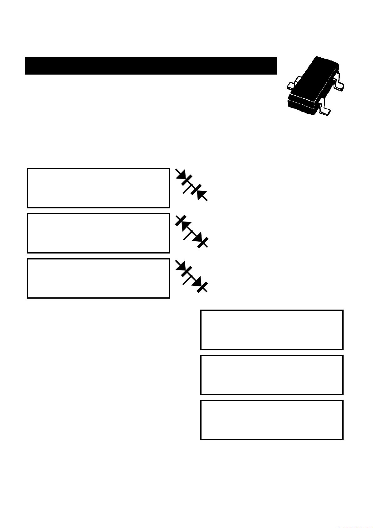
Diode Networks
The Atlas DCA will intelligently identify popular types of
three terminal diode networks. For three terminal devices
such as SOT-23 diode networks, the three test clips must all
be connected, any way round. The instrument will identify the type of diode
network and then display information regarding each detected diode in
sequence. The following types of diode networks are automatically recognised
by the Atlas DCA:
Both cathodes connected
Common cathode
together, such as the BAV70
diode network
Common anode
diode network
Series
diode network
Following the component identification,
the details of each diode in the network
will be displayed.
Firstly, the pinout for the diode is
displayed, followed by the electrical
device.
Anodes of each diode are
connected together, the
BAW56W is an example.
Here, each diode is connected
in series. An example is the
BAV99.
Pinout for D1...
RED GREEN BLUE
information, forward voltage drop and
the current at which the diode was
tested. The value of the test current
depends on the measured forward
voltage drop of the diode.
Following the display of all the details for the first diode, the details of the
second diode will then be displayed.
Page 8
Cath Anod
Forward voltage
D1 Vf=0.64V
Atlas DCA User Guide November 2012 – Rev 10
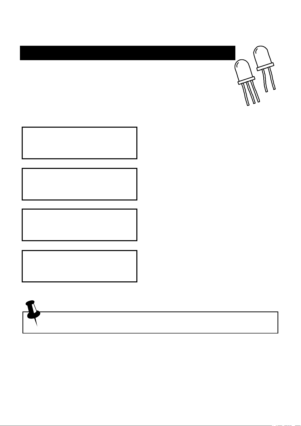
LEDs
An LED is really just another type of diode, however, the
Atlas DCA will determine that an LED or LED network has
been detected if the measured forward voltage drop is larger
than 1.5V. This also enables the Atlas DCA to intelligently
identify bicolour LEDs, both two-terminal and three-terminal varieties.
Like the diode analysis, the pinout, the
LED or diode
forward voltage drop and the associated
junction(s)
RED GREEN BLUE
Cath Anod
Forward voltage
Vf=1.92V
Test current
If=3.28mA
test current is displayed.
Here, the Cathode (-ve) LED terminal is
connected to the Green test clip and the
Anode (+ve) LED terminal is connected
to the Blue test clip.
In this example, a simple green LED
yields a forward voltage drop of 1.92V.
The test current is dependant on the
forward voltage drop of the LED, here
the test current is measured as 3.28mA.
Some blue LEDs (and their cousins, white LEDs) require high
forward voltages and may not be detected by the Atlas DCA.
Page 9
 Loading...