

PDS KTA BOX, KT-150 Installation Instructions Manual
KTA Instructions
Orders Call: 1- 800-688 -5776
INSTALLATION INSTRUCTIONS FOR KTA SYSTEM FAN POWER SUPPLY/INDICATOR
PANEL WITH MATCHING 24-VOLT AC FAN
Description of System:
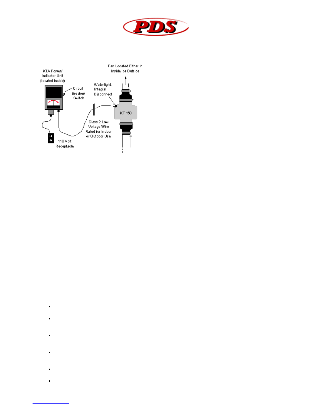
The system consists of one (1) Power Supply/Indicator Box and
one (1) matching 24 volt fan. This system is typically used in
applications where low voltage Class 2 wiring from the power
supply to a remotely located fan is advantageous. It is also
used in applications where it is desirous to have an indication
as to whether the fan is still performing in the manner in
which it was originally installed. The KTA system provides both
of these features.
The KTA Fan system is designed to be a part of a ventilation,
depressurization, or exhaust system where non- explosive or
non-flammable air mixtures will be encountered. The
manufacturer cannot make any representations as to the
entire system of which the KTA and fan are integral parts,
since they are designed and installed by others.
THE PHYSIOLOGICAL EFFECTS REGARDING THE END USE APPLICATION OF THIS PRODUCT CANNOT BE
DETERMINED, SINCE IT IS INTEGRAL TO A SYSTEM TO BE INSTALL BY OTHERS.
The KTA is provided as a matched set consisting of a fan and a power supply/indicator panel. The two units are to
be installed as a matched set. The use of this power supply or fan, in conjunction with any other fan or means of
power, respectively; may be hazardous and will void all warranties. See installation precautions on the following
page. The two matched components are as follows:
POWER SUPPLY/INDICATOR BOX (KTA Box): This is a wall mounted power supply for placement in non - hazardous
environments. It receives power from a 120 volt power receptacle via the 6 foot grounded plug - in cord attached to
the bottom of the box. The unit provides a 24-volt output for power to a matching 24 volt, input fan. It also has an
analog indicator that is proportional to the airflow of the system.
KT - 150 TURBINE FAN: This is a high efficiency 24-volt input, 1/20 hp., in-line fan. It is rated for placement in nonhazardous indoor or outdoor locations. The fan is nominally rated for 270 cubic feet per minute of air with no
restrictions. Actual fan performance will depend upon the restrictions imposed by the duct or piping system. Its
bearings are sealed thus eliminating routine maintenance.
Installation and Use Precautions:
Should you have any questions on the safe installation or use of this system contact the manufacturer at (719) 444-
0646.
WARNING—TO REDUCE THE RISK OF ELECTRIC SHOCK, OR INJURY TO PERSONS, OBSERVE THE FOLLOWING: The
following precautions should be followed The output of the power supply panel to the fan falls under Article 725 of
the National Electric Code for Class 2 power limited circuits.
Use this unit only in the manner intended by the manufacturer if you have questions, contact the
manufacturer.
Neither the KTA power supply box nor the fan have any user serviceable components. However, it may be
necessary to remove the fan from its system to remove debris. In this case, the following precautions for
safe disconnection of the system are to be followed.
Before servicing or removing the fan, flip the switch on the right side of the KTA Box to OFF, disconnect the
power from KTA box by unplugging the KTA from receptacle. Disconnect the cable at the FAN by twisting the
cable connector on the side of the Fan ¼ turn to the left and pulling connector from the socket.
After servicing the fan, reattach the cable to the side of the fan by plugging the cable connector into side of
the FAN and twisting the cable connector collar ¼ turn to the right until it snaps tight. Plug the KTA box
back into the wall receptacle and turn the switch on the side of the KTA box to ON.
Do not reinstall he fan in any manner that will alter the disconnect devices. To avoid physical injury, do not
handle the fan while it is operating
CAUTION THIS FAN IS FOR GENERAL VENTILATING USE ONLY. DO NOT USE TO EXHAUST HAZARDOUS OR
http://radonpds.com/Instructions_KTA/Instructions_KTA.htm[8/16/2010 11:14:41 AM]
KTA Instructions
EXPLOSIVE MATERIALS AND VAPORS.
KTA power supply must only be plugged into 120 volt receptacle. System should be installed in accordance
with local and national mechanical and electrical codes. “WARNING” To reduce the risk of fire or electric
shock, do not use with any solid-state speed control device
If the system is to be removed for warranty repairs, observe the methods described above for disconnection
of both the KTA box and the KTA-150 fan. Both the KTA power supply box and the KTA-1 50 fan along with
the cable are to be returned to the manufacturer as a unit. Prior to shipment call for Return Authorization
Number.
CAUTION—TO REDUCE RISK IF FIRE AND TO PROPERLY EXHAUST AIR, BE SURE TO DUCT AIR OUTSIDE—DO
NOT VENT EXHAUST AIR INTO SPACES WITHIN WALLS OR CEILINGS OR INTO ATTICS, CRAWL SPACES, OR
GARAGES.
INSTRUCTIONS FOR INSTALLATION:
DO NOT PLUG IN POWER SUPPLY UNTIL ALL STEPS ARE COMPLETED.
1. INSTALLATION OF THE FAN IN THE SYSTEM:
The fan should always be installed vertically to prevent condensation from accumulating in the fan housing. If
attached ductwork will convey moist air and the ductwork passes through cool areas or outside, provisions should be
made for the prevention of condensate accumulation in the ductwork. This may be accomplished by insulating the
ductwork and installing a water separation device such as a KT Hydro-Sep™. Non- adherence to these provisions
may affect the life expectancy of this product and will void manufacturer’s warranties. The fan may be located inside
or outside a building, but not in a hazardous environment. Flexible PVC pipe - to-fan inlet or outlet adapters are
available for ease of installation and for noise attenuation. The fan and associated ductwork should be secured so
that the ductwork does not enter the fan housing and cause damage.
2. MOUNTING THE KTA BOX:
The KTA box is designed to be mounted in an INTERIOR, NON-HAZARDOUS location only.
The KTA box should be located so that the 6 ft. grounded power cord can easily reach a 120 volt grounded
receptacle.
The KTA box should be located in an area where the indicator can be easily seen and periodically monitored.
The KTA box should be within 50 feet of fan. A maximum of 50 feet of cable is provided with the KTA box. Do not
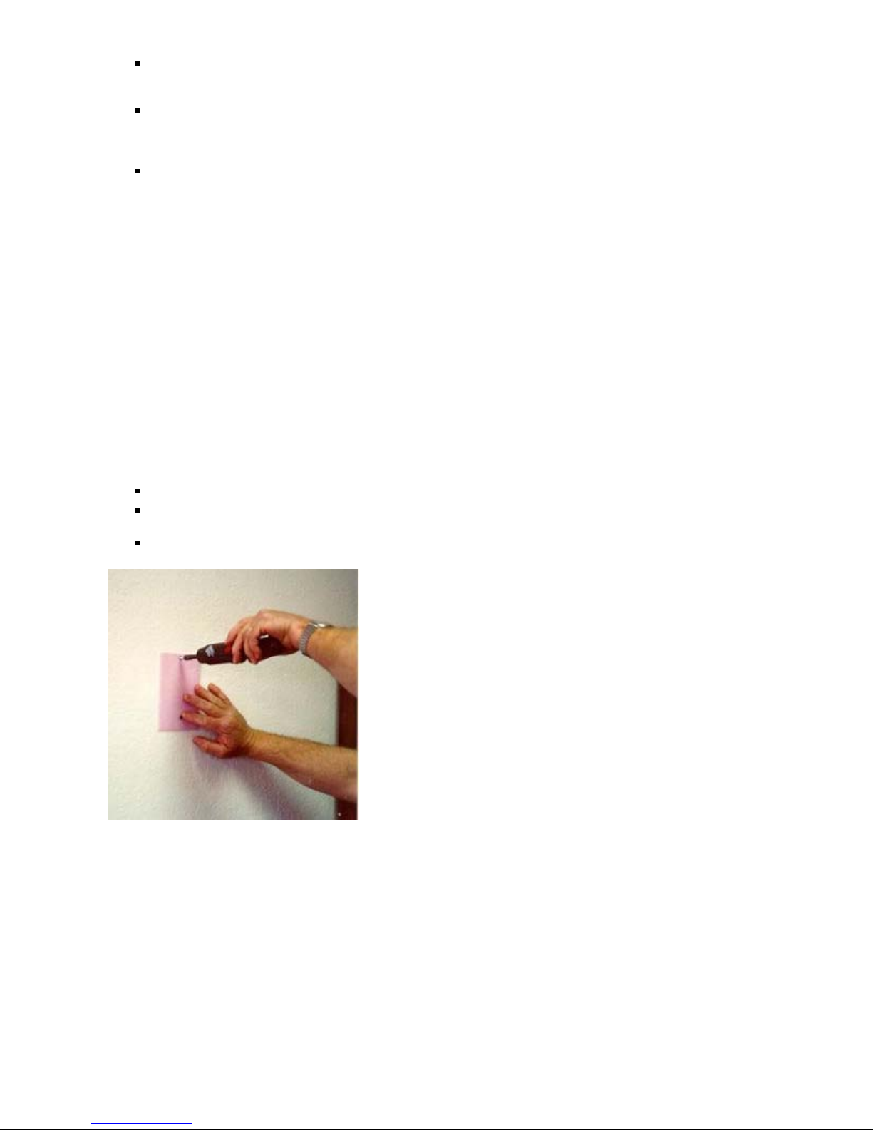
extend low voltage power cable beyond 50 feet, or cut cable less than 10 feet. A mounting template and 2 mounting
screws for the KTA box are included in the envelope. The template provides the correct 4 7/8 inch spacing for the
mounting screws for the KTA box. Use the template to position the screws on the wall or fasten the foam template
to the wall to let it function as a pad. Do not tighten the screws fully into the wall. Allow room for the keyholes on
the backside of the KTA box to slide over the screw heads.
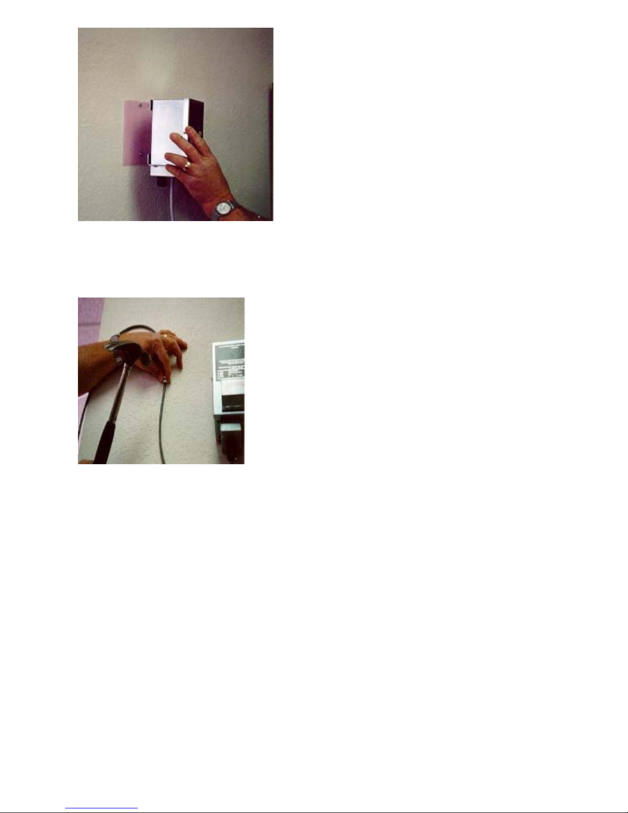
Mount KTA box on screws by placing keyholes in brackets at back of box over screws and pulling down. if box is not
firmly seated on screws, remove box and turn screws further into wall.
http://radonpds.com/Instructions_KTA/Instructions_KTA.htm[8/16/2010 11:14:41 AM]
KTA Instructions
3. ROUTING CABLE FROM FAN TO KTA BOX
Either 25 or 50 feet of two conductor cable is supplied as part of the packaged system. This cable is to be used to
supply the low voltage power to the fan. One end has a quick connect cable attached to it - this end is to be
connected to the panel mounted socket on the side of the fan.
Route the cable from the fan to the location where the KTA box is to be located. Support cable with tie - wrap
fasteners, cable fasteners, or within conduit, depending upon building type and local code requirements. Do not use
metal staples to secure cable. if mounting brackets are to be used for cable, use clip types that are suitable for
securing television or VCR coaxial cable, such as GC Electronics #H7. Do not bury cable. The cable supplied with the
unit is suitable for indoor and outdoor routings. After the cable has been routed to the KTA box cut the excess cable
with a pair of wire cutters (it is advisable to leave some extra cable that would allow the KTA box to be set on a
table or the floor to allow for easier connection of the cable.)
4. CONNECTING WIRE TO KTA BOX
Before connecting the wire to the KTA box make sure that the box is not plugged in and the switch on the side of
the box is OFF.
After cutting off any excess cable, remove 2 inches of the cable jacket from the end of the cable. Be careful not to
strip the insulation from the two wires inside of the cable jacket. Remove the foil wrap around the two exposed
wires (if an un-insulated wire strand is inside the cable, cut this unnecessary wire at the point it is exposed at the
jacket).
http://radonpds.com/Instructions_KTA/Instructions_KTA.htm[8/16/2010 11:14:41 AM]
 Loading...